EP0736648B1 - Scaffold - Google Patents
Scaffold Download PDFInfo
- Publication number
- EP0736648B1 EP0736648B1 EP96105043A EP96105043A EP0736648B1 EP 0736648 B1 EP0736648 B1 EP 0736648B1 EP 96105043 A EP96105043 A EP 96105043A EP 96105043 A EP96105043 A EP 96105043A EP 0736648 B1 EP0736648 B1 EP 0736648B1
- Authority
- EP
- European Patent Office
- Prior art keywords
- scaffold
- bearing
- horizontal
- crossmember
- lift
- Prior art date
- Legal status (The legal status is an assumption and is not a legal conclusion. Google has not performed a legal analysis and makes no representation as to the accuracy of the status listed.)
- Expired - Lifetime
Links
Images


Classifications
-
- E—FIXED CONSTRUCTIONS
- E04—BUILDING
- E04G—SCAFFOLDING; FORMS; SHUTTERING; BUILDING IMPLEMENTS OR AIDS, OR THEIR USE; HANDLING BUILDING MATERIALS ON THE SITE; REPAIRING, BREAKING-UP OR OTHER WORK ON EXISTING BUILDINGS
- E04G1/00—Scaffolds primarily resting on the ground
- E04G1/15—Scaffolds primarily resting on the ground essentially comprising special means for supporting or forming platforms; Platforms
- E04G1/152—Platforms made of metal or with metal-supporting frame
-
- E—FIXED CONSTRUCTIONS
- E04—BUILDING
- E04G—SCAFFOLDING; FORMS; SHUTTERING; BUILDING IMPLEMENTS OR AIDS, OR THEIR USE; HANDLING BUILDING MATERIALS ON THE SITE; REPAIRING, BREAKING-UP OR OTHER WORK ON EXISTING BUILDINGS
- E04G7/00—Connections between parts of the scaffold
- E04G7/02—Connections between parts of the scaffold with separate coupling elements
- E04G7/28—Clips or connections for securing boards
-
- E—FIXED CONSTRUCTIONS
- E04—BUILDING
- E04G—SCAFFOLDING; FORMS; SHUTTERING; BUILDING IMPLEMENTS OR AIDS, OR THEIR USE; HANDLING BUILDING MATERIALS ON THE SITE; REPAIRING, BREAKING-UP OR OTHER WORK ON EXISTING BUILDINGS
- E04G1/00—Scaffolds primarily resting on the ground
- E04G1/15—Scaffolds primarily resting on the ground essentially comprising special means for supporting or forming platforms; Platforms
- E04G2001/158—Platforms supported by spigots which engage through holes in the platform
Definitions
- Scaffolds have stems, horizontal bars, and diagonal bars in order a stable and somewhat rigid Build space structure.
- the horizontal bars include Horizontal support bars, which are usually much shorter than the other horizontal bars.
- On the horizontal support bars become the scaffolding floors essential for scaffolding with the running and working areas for the actual Supported use of the scaffold.
- the interaction between the various elements of the supporting structure and at least in the tread plane torsionally rigid scaffolding floors can be used to stabilize the whole framework and essentials contribute. However, this is due to the circumstances of the Manufacturing, building, growing and using game to take into account.
- the scaffolding is either with vertical scaffolding frames, which are usually vertical and normal to the building wall be set up, or with individual stems and Node elements for the connection between stems and Horizontal and diagonal bars built.
- the invention deals with improved solutions Scaffolds with individual stems and with knot elements to connect the rods and as 'Module scaffolding' can be called.
- For the node elements various configurations are known. Below there are different arrangements with cup-like rings on the Stems in which the horizontal rods and hooks from above other horizontal elements and the connecting elements for Diagonal bars hooked in and with additional means be secured.
- the scaffolding floors are attached to the in different ways Horizontal support bars connected.
- One uses cylindrical support bars, are usually claw-like Hooks placed from above and mostly spring-loaded and / or locked holding fingers from below to prevent lifting recorded.
- the horizontal bars have wedge heads at their ends, which have a horizontal slot in the middle, which allows those below and above Push the headboard over the perforated disc from the side and then a wedge through the openings in the two Headboards and through the opening in the perforated disc stuck.
- top and Bottom can serve as a running and work surface double prism-shaped support elements on their end faces, which are also on the upper edge surfaces of the Vertical leg of the U-shaped, open at the top Horizontal bars are placed. With these there is also one Side shift possible if not additional Aids are applied.
- EP-A-0 308 882 discloses a scaffold floor part for bridges smaller, not parallel and more limited at right angles Running and working areas within a scaffold. there there are two horizontal support bars inside the scaffold Commitment. A first horizontal support bar is considered an after U-profile open at the top, which is attached to the wedge heads Perforated disks of the stems of the scaffold are connected and in which the scaffolding floor elements are hung using hooks become.
- horizontal support bars used which are welded to the scaffolding posts are and have vertical pins on which on the scaffold floors existing hangers are hooked in.
- the present invention has the technical problem or the task is based on scaffolding with support structure element arrangements of the type mentioned the holding, fixing and Supporting devices for scaffolding floors on the structure and associated Design elements so that manufacturing, Assembly, disassembly and use can be improved by the formation of the scaffolding and the support of the occurring Forces are improved and optimized.
- the invention further aims by Association of advantageous features from different Interchangeability and that arbitrary merging of elements of different To enable scaffolding systems, but above all on the other hand with a simple structure and cheap and inexpensive Manufacturing options a particularly good one, in several Directionally stable connection between the scaffold frame floors and the stems of the overall structure of the scaffold enable.
- the scaffold according to the invention is characterized by the features of given independent claim 1. advantageous Refinements and developments are the subject of dependent claims.
- consoles have a fastening on the scaffold arm and a little lower horizontal, usually loose, lower console support, with an inclined strut to the outer end of the Horizontal bar or horizontal support element of Console is connected so that all supporting forces on the Handle-side of the console can be introduced into the handle.
- the attachment to the respective one is known Node element. So far, U-shaped horizontal support elements with wedge heads attached to perforated disks provided or there are horizontal support elements with vertical pins and cup attachment common.
- a preferred alternative embodiment of the Scaffold according to the invention is characterized in that the support structure element arrangement designed with consoles is in each case instead of the horizontal support bar Have horizontal support element, with one at one end attached wedge head with one free end, with one on Fasten the wedge-head end and rest on the stem, approximately perpendicular to the horizontal support element Vertical strut leading oblique strut as well as with vertical pins, to the securing holes in the scaffolding or Console scaffolding floors are arranged in suitable dimensions.
- the console attachment with some known per se Wedge heads with above and below the perforated disc adjacent support surface and wedge bracing also offers Loose wedge provides great security against undesired falling of parts and especially in Connection with the connection secured via the pins between console scaffolding floors and horizontal support element one in overall strength and overall stiffness significantly improved overall scaffolding design.
- the special wedge head design for the Connection to the handle can be the loose handle system of the lower Struts are successfully used in a stable manner.
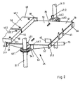
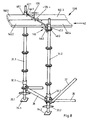
- the frame 30 has stems 31.1 and 31.2, which are in Support in the usual way on starting pieces 32.1 and 32.2. These in turn are based on nuts 33.1 and 33.2 adjustable support feet 34.1 and 34.2. In the usual Ways are also referred to as horizontal bars Horizontal longitudinal bar 35 and horizontal cross bar 36 and also diagonal bars 37 referred to as diagonal bars intended. These scaffolding elements are in the usual way often provided on the scaffold.
- a unusually wide horizontal support bar 45 To support the Scaffold floors 40.1 ... 4 of the first scaffold level 42 is a unusually wide horizontal support bar 45 provided, which with the help of provided by end Wedge heads 46.1 and 46.2 engage wedges 47.1 and 47.2 the perforated discs 48.1 and 48.2 of the stems 31.1 and 31.2 in which is wedged in the usual way with such scaffolding.
- This extremely stable and also safe against tipping forces Connection which the occurring forces with the Head end faces directly into the stem tube is 3 and 4 illustrated in more detail.
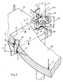
- the horizontal support bar 45 has a flat base support plate 50 and end pin support walls 51.1 and 51.2.
- Form cross struts 52 under the floor support plate 50 a structured, rigid element with an im essential box-shaped horizontal bar support tube 53, at the ends 54.1 and 54.2 the wedge heads 46.1 and 46.2 are preferably attached by welding. All Components usually exist for those as bulk goods used steel scaffolding. For those special costly, but for quick transportation as well the quick assembly and disassembly of inexpensive light metal frames they can also consist of light metal.
- the scaffolding floors 40.1 and 40.2 shown in Fig. 2 are just like the scaffolding floors 40.3 and 40.4 in Distance from its shorter end face 55 and from the long side vertical surfaces 56 in approximately the same Spaced, with securing holes or through-fixing openings 57.1 and 57.2 designed floor support means. These are usually designed with vertical sleeves 58. Wood, but also metal, can be used as scaffolding floor material or composite materials formed, common materials for Scaffold floors can be used.
- the dimensions of both the Scaffolding floor elements as well as for the arrangement of the Through-fixing openings 57.1 and 57.2 and their Distances from each other and from the forehead surfaces of the Scaffolding floors correspond to the scaffolding system to which they belong Usually include and the dimensions of the horizontal support bar are in accordance with those otherwise used To design scaffolding components.
- the free receiving length 67 is over the bearing surface 61 somewhat lower or at most equal to the height of 68 Tread 69 of the scaffolding floor 40 over the Support surface 61.
- Their upper ends 70 are more common Way slightly tapered to insert into the Through-fixing holes 57 to facilitate.
- Your Attachment ends 66 have an attachment length 73 that according to the usual dimensions and designs manufacturing technology favorable and the power ratios Appropriate attachment or as Transitional area for a formative training in one chipless forming process can serve.
- FIG. 3 illustrates the power transmission from one, as a result of the stress 3, bent scaffold floor 40 on the stem 31.
- the relatively precisely arranged Vertical sleeve 58 is supported in the area of the upper end 70 of the vertical pin 65 at the upper pin force application point 6 on one side and in the area of the fastening end 66 of the vertical pin 65 at the lower pin force application point 7 on the opposite side, making a relative large pin support spacing 5 between the two counter-acting pin support forces 8 and 9 of the applied moment 10 is to be considered.
- the upper head part 19 is supported with its upper inner limit 24.1 on one side of the wedge head 46 at the upper perforated disc force application point 13 with the upper perforated disc support force 11, while on the opposite side of the Wedge head 46 of the lower head part 20 with its lower Internal limitation 24.2 at the lower perforated disc force application point 14 with the lower perforated disc support force 12 supported. These support forces engage on the perforated disc the effective horizontal distance 4.
- the wedge head 46 is supported also on one side with its upper head part 19 at the upper point of tangential force 17 with the upper one tangential head support force while on the opposite side of the lower head part 20 at the lower Tangential force application point 18 with the lower one supports tangential head part supporting force.
- This Support forces engage in the effective vertical distance 29 Handle 31.
- the particularly advantageous design of the wedge head 46 leads in connection with the large effective distances of the Support force application points on perforated disk 48 (Horizontal distance 4) and in particular on the handle 31 (Vertical distance 2 and distance 29) to an optimal Power and torque transmission to the handle with which Consequence that greater static and dynamic loads are tolerable or that the corresponding scaffolding parts weight-optimized dimensions.
- the horizontal support bar 45 has on its underside Drain openings 84, so that a drain option for fluid media for surface treatment or for Rainwater is created.
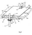
- an anti-lift device 95 with a Bridging and anti-lift-off plate 80 provided, the support ends 81 with a support length 82 on the Support scaffolding floors 40.1 ... 4. In the middle are on its bottom securing hook 85 attached, which in Intervene with safety openings 86 with an elongated hole character.
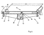
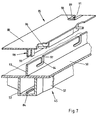
- FIG. 7 shows the security principle one of the bottom support plate 50 of the horizontal support bar 45 towering bending reinforcement and Locking washer 93 with hook slot 94 and above Engagement or insertion opening 97 is provided.
- To the another is under bridging and Anti-lift plate 80 also as a U-profile customizable double-bar arrangement 98, with receiving opening 99 to accommodate the locking plate 93, downwards designed, where appropriate Shift locking pins 96 are attached.
- anti-retraction means can also be used various types, especially with the help of Safety flap 89 may be provided.
- This design also shows the advantageous principles of modular scaffolding systems with perforated disks and themselves with their Support end faces on the tubes of the stems directly supporting wedge heads and from above and below with respect the wedge head elements inserted wedges.
- the horizontal support bar has an upper, support surface 262 and lower on both sides of the horizontal support beam 245 running, parallel contact surfaces 263.1 and 263.2 from Pin and pad supports 264.1 and 264.2.
- the Boundary surface 262 is approximately at the same height 276 as the surface 277 of the scaffold floors 240.1 and 240.2 so that the distance 278 of the upper boundary surface 262 from the Support surface 263 approximately the thickness 279 of the scaffold floors 240 equivalent.
- the remaining features of the horizontal beam 245 correspond essentially to that described first Variant.
- they are cross struts 252 below the upper boundary surface 262 provided a structured, rigid element with the pin and pad support 264 and an im essential box-shaped horizontal bar support tube 253 form, with wedge heads at the ends in a conventional manner are preferably attached by welding.
- scaffolding elements can occur or make sense be part of the scaffold with scaffold floors 339 too provided with claws or Claws 343 on horizontal support legs that are open at the top Support 344 while next to it with its contact surface part 359 on the horizontal contact surface 361 overlying scaffold floors 340 with in Distance from the front and side surfaces
- Through-fixing openings 357.1 and 357.2 are provided, preferably with supportive, power-transmitting and enabling good conditions of use Vertical sleeves 358 are equipped.
- Such a Horizontal support bar 345 is shown in FIG. 13 with its two different scaffold frame floors 339 and 340 and Connection devices shown schematically.
- a wedge head 346 of here scaffolding system described in more detail with perforated disks 348 and Push-through wedges 347 shown.
- a fastening device be provided to the node element of the other scaffolding system fits.
- the vertical pins can in the connection area Horizontal support bars designed in different ways to meet the different requirements and constructive conditions of basic scaffolding systems To take into account.
- Figs. 14 and 15 can on the one hand in the area of their fastening ends 464 cylindrical vertical pins 463 may be provided.
- preferably semi-cylindrical Vertical pins 465 may be provided for one smaller pin spacing 416 or a larger width 418 of the horizontal bar 445 with its Horizontal bar support tube 453 technologically favorable can be realized.
- the vertical pins 463 and 465 are on the pin bearing walls 449.1 and 449.2 or 451.1 and 451.2 outside with their lower fastening ends 464 or 466 welded or in other ways by forming Education pronounced.
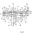
- the Console 500 deals with a wedge head 46.3.
- the Console 500 has a horizontal support element 501, which with one attached to the wedge head end 554.1, approximately extending perpendicular to the horizontal support element 501
- Vertical strut 502 and one from the free end or free end 554.2 to the vertical strut 502, in particular to their End 504 leading oblique strut 503 is equipped.
- the End 504 of the oblique strut 503 lies on the outside of the Tube 505 of the stem 31.2 loosely, while the wedge 47.3 the wedge head 46.3 in the usual way on the disc 48.2 sets.
- At the free end 554.2 of the horizontal support element 501 is a short vertical tube 506 fixed vertically with a weld seam 507 and has a thinner upper tube section 508 with a Transverse hole 509 for attaching further scaffolding elements, especially stem elements.
- the horizontal support element 501 has a flat bottom support plate 550 and end pin support walls 551.1 and 551.2.
- the horizontal support element 501 is with a essential box-shaped support element support tube 553 formed, at the wedge head end 554.1 the wedge head 46.3 is preferably attached by welding. All Components usually exist for as bulk goods used steel scaffolding. For those special costly, but for quick transportation as well the quick assembly and disassembly of inexpensive light metal frames they can also consist of light metal.
- the console scaffold floors 140.5 and 140.6 shown in Fig. 20 are shown just like that Scaffolding floors 140.1 ... 4 at a distance from their shorter end face 155 and from the Longitudinal vertical surfaces 156 at approximately the same distance horizontal through holes 57.1 and 57.2. This are usually designed with vertical sleeves 58.
- Scaffolding floor material can be wood, but also metal or composite materials formed, common materials for Scaffold floors can be used.
- the dimensions of both the Scaffolding floor elements as well as for the arrangement of the Through-fixing openings 57.1 and 57.2 and their Distances from each other and from the forehead surfaces of the Scaffolding floors correspond to the scaffolding system to which they belong Usually include and the dimensions of the horizontal support bar are in accordance with those otherwise used To design scaffolding components.
- the free receiving length 67 is over the bearing surface 561 somewhat lower or at most equal to the height of 68 Tread 169 of the scaffolding floors 140.5 and 140.6 above the Support surface 561.
- Their upper ends 70 are more common Way slightly tapered to insert into the Through-fixing holes 57 to facilitate.
- Your Attachment ends 66 have an attachment length 73 that according to the usual dimensions and designs manufacturing technology favorable and the power ratios Appropriate attachment or as Transitional area for a formative training in one chipless forming process can serve.
- the horizontal support element 501 has on its underside Drain openings 584, so that a drain option for fluid media for surface treatment or for Rainwater is created.
- a Anti-lift means 595 with a bridging and Anti-lift plate 580 is provided, the Support ends 581 with a support length 582 on the Support console scaffold floors 140.5 and 140.6.
- the Support ends 581 with a support length 582 on the Support console scaffold floors 140.5 and 140.6.
- safety hooks 585 on their underside attached, which in securing openings 586 Intervene elongated character.
- the hook ends 587 of the Securing hooks 585 are then under the support surface 588 of the horizontal support member 501 when the bridging and Lift-off plate 580 in the direction of crosswise Longitudinal extension of scaffold floors 140.5 and 140.6 extending securing opening 586 is moved so that it is in the anti-counterfeiting position as it stands out DE 30 20 389 C2 results.
- Can be used for backfeed protection various auxiliary elements can be provided.
- a Safety flap 589 which can be opened using a Hinge joint 590 is attached and by means of their Slot 591 on the inner wedge surface 92 of the supports the respective wedge 47.3 and so the Prevention of backfeed in a known manner.
- Stop tab 520 may be provided.
- this can be an end predominantly perpendicular and normal to it Have double web or U-profile arrangement 598.
- Bridging plate 511 is provided to bridge the gap 576 between the Scaffold floors 140.1 and 140.3 on the one hand and the Console scaffolding floors 140.5 and 140.6 on the other hand. This faces the end a lift-off fixation tab 512 on the down placed under the two bridging and Lift-off protection plates 80 and 580 engage.
- the width 515 the lift fixation tab 512 is smaller and the width the bridging plate 511 is larger than that Lateral distance 514 between the scaffold floors 140.1 or 140.3 and the console scaffolding floors 140.5 and 140.6.
- the invention relates to a scaffold (30) or scaffold part with a support structure element arrangement, which has a torsionally rigid space structure with the aid of supports (31), horizontal bars (35, 36, 45) and Forms diagonal bars (37), and module grid dimensions in all three spatial directions and longitudinal connection grid dimensions for standard connecting scaffold floors (40.1 to 40.4).
- Horizontal support elements or Support bar (45) is connected by means of a wedge (47) via wedge heads (46), which are plugged onto horizontally attached perforated disks (48) of the stems (31).
- the scaffold floors (40) are open Horizontal support elements or support bolts (45) are at least partially secured against displacement by means of securing pins attached to them and supported against being lifted off.
Abstract
Description
Die vorliegende Erfindung betrifft ein Gerüst mit
Tragstruktur-Element-Anordnung, wobei ein verwindungssteifes
Raumtragwerk unter Zuhilfenahme von Stielen, Horizontalstäben
und Diagonalstäben gebildet ist, das Gerüst Modul-Rastermaßen
in allen drei Raumrichtungen sowie Längsanschluss-Rastermaßen
für die Gerüstböden gehorcht und wobei
das Breiten-Rastermaß entsprechend der Breite des Personenarbeitsraumes
gewählt ist und das Höhen-Rastermaß einem
Höhenmodulmaß zur variablen Unterteilung einer Personenarbeitshöhe
entspricht und das Längs-Rastermaß der Horizontalerstreckung
einer Feldgröße entspricht und die Längsanschluss-Rastermaße
entsprechend der Auflageelementgestaltung
kleiner als die Längs-Rastermaße sind, mit
folgenden Merkmalen:
Gerüste haben Stiele, Horizontalstäbe und Diagonalstäbe, um ein standfähiges und einigermaßen verwindungssteifes Raumtragwerk aufzubauen. Zu den Horizontalstäben gehören Horizontal-Tragriegel, die in der Regel wesentlich kürzer als die anderen Horizontalstäbe sind. Auf den Horizontal-Tragriegeln werden die für Gerüste wesentlichen Gerüstböden mit den Lauf- und Arbeitsflächen für den eigentlichen Einsatz des Gerüstes abgestützt. Das Zusammenwirken zwischen den verschiedenen Elementen der Tragstruktur und den zumindest in der Laufflächenebene sehr verwindungssteifen Gerüstböden kann zur Stabilisierung des ganzen Gerüstes herangezogen werden und wesentliches beitragen. Dabei ist jedoch das von den Gegebenheiten der Herstellung, des Aufbauens, des Anbauens und der Benutzung herrührende Spiel zu berücksichtigen.Scaffolds have stems, horizontal bars, and diagonal bars in order a stable and somewhat rigid Build space structure. The horizontal bars include Horizontal support bars, which are usually much shorter than the other horizontal bars. On the horizontal support bars become the scaffolding floors essential for scaffolding with the running and working areas for the actual Supported use of the scaffold. The interaction between the various elements of the supporting structure and at least in the tread plane torsionally rigid scaffolding floors can be used to stabilize the whole framework and essentials contribute. However, this is due to the circumstances of the Manufacturing, building, growing and using game to take into account.
Die Gerüste werden entweder mit vertikalen Gerüstrahmen, die in der Regel vertikal und normal zur Gebäudewand aufgestellt werden, oder mit einzelnen Stielen und Knotenelementen für die Verbindung zwischen Stielen und Horizontal- sowie Diagonalstäben aufgebaut. Die Erfindung befaßt sich mit verbesserten Lösungsmöglichkeiten an Gerüsten, die mit einzelnen Stielen und mit Knotenelementen zur Verbindung der Stäbe aufgebaut werden und als 'Modul-Gerüste' bezeichnet werden. Für die Knotenelemente sind verschiedene Ausgestaltungen bekannt. Darunter gibt es verschiedene Anordnungen mit tassenartigen Ringen an den Stielen, in welchen von oben Haken der Horizontalstäbe und sonstiger Horizontalelemente sowie der Anschlußelemente für Diagonalstäbe eingehängt und mit zusätzlichen Mitteln gesichert werden. Dabei kennt man Sicherungen mit schräg eingeschlagenen Keilen.The scaffolding is either with vertical scaffolding frames, which are usually vertical and normal to the building wall be set up, or with individual stems and Node elements for the connection between stems and Horizontal and diagonal bars built. The invention deals with improved solutions Scaffolds with individual stems and with knot elements to connect the rods and as 'Module scaffolding' can be called. For the node elements various configurations are known. Below there are different arrangements with cup-like rings on the Stems in which the horizontal rods and hooks from above other horizontal elements and the connecting elements for Diagonal bars hooked in and with additional means be secured. One knows fuses with oblique hammered wedges.
Wenn diese Keile nicht befestigt sind, können die Einhängehaken aus den Tassen nach oben ausgehoben werden. Sind mit ihnen großflächige Elemente des Gerüstes verbunden, so kann bei stärkerem Wind oder Sturm beispielsweise das mit dem Auflageriegel verbundene Gerüstbodenelement gemeinsam mit diesem abgehoben werden und zu schweren Schäden an Menschen, Gebäuden, Autos und sonstigen Gegenständen führen.If these wedges are not attached, they can The hooks are lifted out of the cups. With them are large-scale elements of the scaffolding connected, so in stronger wind or storm for example, that associated with the support bar Scaffolding floor element can be lifted off together with this and cause serious damage to people, buildings, cars and other objects.
Die Gerüstböden werden auf verschiedene Weise mit den Horizontal-Tragriegeln verbunden. Verwendet man zylindrische Tragriegel, werden in der Regel klauenartige Haken von oben aufgelegt und mit zumeist gefederten und/oder verriegelten Haltefingern von unten gegen Abheben festgehalten.The scaffolding floors are attached to the in different ways Horizontal support bars connected. One uses cylindrical support bars, are usually claw-like Hooks placed from above and mostly spring-loaded and / or locked holding fingers from below to prevent lifting recorded.
Für verschiedene Einzel- und Sonderanwendungen sind aus den Gebrauchsmustern DE-U 85 13 983 und DE-U-85 13 985 Bohlengerüste aus Vertikalrahmen und Belagstafeln bzw. Gerüstböden bekannt, bei denen die obere Traverse des Gerüstrahmens zwischen den beiden senkrechten, aus Rundrohr gefertigten Stielen des Rahmens eingeschweißt ist und für das Fixieren der Belagstafeln vertikal aufragende Stifte trägt, die dem jeweiligen Modulmaß und den verschiedenen Individualmaßen entsprechend angeordnet sind.For various individual and special applications are from the Utility models DE-U 85 13 983 and DE-U-85 13 985 scaffolding from vertical frames and covering panels or scaffolding floors known in which the upper cross member of the scaffold frame between the two vertical, made of round tube Stems of the frame are welded in and for fixing the covering boards carries vertically upright pins, which the respective module dimensions and the various individual dimensions are arranged accordingly.
Die auch die Abstände der benachbart angeordneten Stifte voneinander und die Breiten der Traversen berücksichtigende Konstruktion bietet vor allem durch das Verschweißen der oberen Traverse mit den Vertikalstielrohren einen steifen Rahmen, der nur entsprechend seinen Anschlußmaßen und Anschlußgegebenheiten benutzt werden kann, jedoch nicht geeignet ist, an im übrigen unterschiedlich gestalteten Modul-Gerüsten eingesetzt zu werden. Bei solchen Modul-Gerüsten werden gerade lose Stiele mit Angriffsmitteln für Anschlußköpfe von Traversen eingesetzt, was bei Rahmengerüsten nicht der Fall ist.The also the spacing of the adjacent pins from each other and taking into account the widths of the trusses Construction offers mainly by welding the upper crossbar with the vertical support tubes a stiff Frame that only according to its connection dimensions and Connection conditions can be used, however not is suitable for otherwise differently designed Module scaffolds to be used. With such modular scaffolding are just loose stalks with attack means for Connection heads of trusses used, which at Scaffolding is not the case.
Eine andere Anwendung von Traversen mit Stiften ist aus DE-A 38 24 922 bekannt. Dabei geht es darum, jeweils eine die hölzernen Sprossen eines Holzleiterngerüstes übergreifend, im Profil etwa hutförmige Halteeinrichtung aufzulegen. Diese Halteeinrichtung hat auswärts ragende Schenkel mit Tragrohren für die Fixierstifte der Gerüstböden, aber keine stirnseitig angeschlossenen Hilfsmittel, um mit den sonstigen Anschlußeinrichtungen eines Stabwerksknotens verbunden zu werden. Da es sich um ein individuell aufzubauendes Holzleiterngerüst handelt, sind auch die Abmessungen bezüglich eines für das ganze Gerüst maßgebenden Grundrastersystems nicht gegeben. Den vorgenannten Schriften sind keine-Anregungen zu entnehmen, Traversen mit Fixierstiften für Gerüstböden mit besonders stabilen, auf die Kippkräfte Rücksicht nehmenden, stirnseitig vorgesehenen Stabwerks-Knoten-Köpfen für Lochscheiben an Stielen auszustatten.Another application of trusses with pins is out DE-A 38 24 922 known. It's about one at a time the wooden rungs of a wooden ladder scaffold comprehensive, approximately hat-shaped holding device in profile hang up. This holding device has outwardly projecting Leg with support tubes for the fixing pins of the Scaffolding floors, but no front-connected ones Tools to help with the other connection facilities of a truss node. Since it is an individually constructed wooden ladder scaffold are also the dimensions with respect to one for the whole Framework framework system not applicable. The No suggestions can be found in the aforementioned writings. Trusses with fixing pins for scaffolding floors with special stable, taking into account the tipping forces, front end of the framework knot heads for To equip perforated discs on stems.
Andere Befestigungen, wie sie vor allem bei Modul-Gerüsten verwendet werden haben auf den Stielen in bestimmten Abständen befestigte Lochscheiben und haben in der Regel eine nach oben offene U-förmige Horizontal-Tragriegel-Ausbildung.Other fastenings, such as those used for modular scaffolding have been used on the stems in certain Distances attached and usually have perforated disks an upwardly open U-shaped horizontal support bar design.
Die Horizontal-Riegel besitzen an ihren Enden Keilköpfe, welche etwa in der Mitte einen Horizontalschlitz aufweisen, der es gestattet, den darunter und darüber befindlichen Kopfteil von der Seite über die Loch-Scheibe zu schieben und dann einen Keil durch die Öffnungen in den beiden Kopfteilen und durch die Öffnung in der Loch-Scheibe zu stecken.The horizontal bars have wedge heads at their ends, which have a horizontal slot in the middle, which allows those below and above Push the headboard over the perforated disc from the side and then a wedge through the openings in the two Headboards and through the opening in the perforated disc stuck.
Auf die Kanten der U-schienenartigen Tragriegel werden je Gerüstboden zumindest zwei an seiner jeweiligen Stirnseite befestigte Klauen aufgelegt. Diese greifen mit dem etwa 1 bis 2 cm hohen Hakenteil über die Tragkante. Mit Spiel von oben aufliegende Abhubsicherungen verhindern das Abheben. Depending on the edges of the U-rail-like support bars Scaffolding floor at least two on its respective end face attached claws. With the 1st up to 2 cm high hook part over the supporting edge. With game from Lift safeguards on top prevent lifting.
Durch die mehrfach verzahnte Kellkonstruktion ist schon bei nicht festgeschlagenem, jedoch durchgestecktem Keil und aufgelegter Abhubsicherung keine Trennung des Gerüstbodens und des Tragriegels von der Tragstruktur mehr möglich. Allerdings sind bei dieser Anordnung nicht alle Elemente durch Formschluß und Reibschluß miteinander fest verbunden.Thanks to the multi-toothed cellar construction, not wedged but inserted wedge and Lifting protection applied does not separate the scaffolding floor and the support bar of the support structure more possible. However, not all elements are in this arrangement firmly connected to each other by positive locking and friction locking.
Auf Umschlag verwendbare Gerüstböden, bei denen Ober- und Unterseite als Lauf- und Arbeitsfläche dienen können, haben an ihren Stirnseiten doppelprismenförmige Auflageelemente, die ebenfalls auf die oberen Kantenflächen der Vertikalschenkel der U-förmigen, nach oben offenen Horizontalriegel aufgelegt werden. Auch bei diesen ist eine Seitenverschiebung möglich, wenn nicht zusätzliche Hilfsmittel angewandt werden. Scaffolding floors that can be used for handling, in which top and Bottom can serve as a running and work surface double prism-shaped support elements on their end faces, which are also on the upper edge surfaces of the Vertical leg of the U-shaped, open at the top Horizontal bars are placed. With these there is also one Side shift possible if not additional Aids are applied.
Die EP-A-0 308 882 offenbart ein Gerüstbodenteil für Überbrückungen kleiner, nicht parallel und rechtwinklig begrenzter Lauf- und Arbeitsflächen innerhalb eines Gerüstes. Dabei kommen innerhalb des Gerüstes zwei Horizontal-Tragriegel zum Einsatz. Ein erster Horizontal-Tragriegel ist als ein nach oben offenes U-Profil ausgebildet, das über Keilköpfe an Lochscheiben der Stiele des Gerüstes angeschlossen ist und in das die Gerüstbodenelemente über Einhängeklauen eingehängt werden.EP-A-0 308 882 discloses a scaffold floor part for bridges smaller, not parallel and more limited at right angles Running and working areas within a scaffold. there there are two horizontal support bars inside the scaffold Commitment. A first horizontal support bar is considered an after U-profile open at the top, which is attached to the wedge heads Perforated disks of the stems of the scaffold are connected and in which the scaffolding floor elements are hung using hooks become.
In einem weiteren Ausführungsbeispiel werden Horizontal-Tragriegel eingesetzt, die an die Gerüststiele angeschweißt sind und Vertikalstifte aufweisen, an denen an den Gerüstböden befindliche Einhängelaschen eingehängt werden.In a further embodiment, horizontal support bars used, which are welded to the scaffolding posts are and have vertical pins on which on the scaffold floors existing hangers are hooked in.
Der vorliegenden Erfindung liegt das technische Problem bzw. die Aufgabe zugrunde, bei Gerüsten mit Tragstruktur-Element-Anordnungen der eingangs genannten Art die Halte-, Festlegeund Abstützeinrichtungen für Gerüstböden am Tragwerk und zugehörige Elemente so auszugestalten, dass Herstellung, Montage, Demontage und Benutzung verbessert werden, indem die Ausbildung des Gerüstes und die Abstützung der auftretenden Kräfte verbessert und optimiert werden.The present invention has the technical problem or the task is based on scaffolding with support structure element arrangements of the type mentioned the holding, fixing and Supporting devices for scaffolding floors on the structure and associated Design elements so that manufacturing, Assembly, disassembly and use can be improved by the formation of the scaffolding and the support of the occurring Forces are improved and optimized.
Die Erfindung zielt weiterhin darauf ab, durch die Vereinigung vorteilhafter Merkmale aus verschiedenen Gerüstsystemen einerseits die Austauschbarkeit und das beliebige Zusammenfügen von Elementen verschiedener Gerüstsysteme zu ermöglichen, vor allem aber andererseits bei einfachem Aufbau sowie günstigen und preiswerten Herstellungsmöglichkeiten eine besonders gute, in mehreren Richtungen formstabile Verbindung zwischen den Gerüstrahmenböden und den Stielen der Gesamttragstruktur des Gerüstes zu ermöglichen. The invention further aims by Association of advantageous features from different Interchangeability and that arbitrary merging of elements of different To enable scaffolding systems, but above all on the other hand with a simple structure and cheap and inexpensive Manufacturing options a particularly good one, in several Directionally stable connection between the scaffold frame floors and the stems of the overall structure of the scaffold enable.
Das erfindungsgemäße Gerüst ist durch die Merkmale des unabhängigen Anspruchs 1 gegeben. Vorteilhafte Ausgestaltungen und Weiterbildungen sind Gegenstand der abhängigen Ansprüche.The scaffold according to the invention is characterized by the features of given independent claim 1. advantageous Refinements and developments are the subject of dependent claims.
Das erfindungsgemäße Gerüst ist demgemäß durch folgende Merkmale gekennzeichnet:
- die Sicherungs-Löcher weisen durchgehende Vertikalhülseh auf, in die die Vertikalstifte relativ passgenau einführbar sind;
- der Horizontal-Tragriegel weist Eingriffsfreiräume für die Aufnahme von zumindest einem, die Enden der Gerüstböden abdeckenden Abhubsicherungs-Mittel auf.
- the securing holes have continuous vertical sleeves into which the vertical pins can be inserted with a relatively precise fit;
- the horizontal support bar has free spaces for receiving at least one anti-lifting device covering the ends of the scaffolding floors.
Dadurch daß man einerseits die besonders sichere und nach dem Verkeilen auch in allen Richtungen besonders stabile Knotenkonstruktion mit Lochscheibe und horizontal geschlitztem Keilkopf verwendet und andererseits an dem Riegel die relativ langen und die Gerüstböden auch gegen seitliche Verschiebung sichernde Stift-Loch-Verbindungen mit geeigneten Paßabmessungen einsetzt, erhält man eine schon beim und nach dem losen. Zusammenfügen automatisch in mehreren Richtungen besonders stabile Verbindung, die auch bei auftretenden Verdrehkräften besonders torsionsstabil ist und auch gegen Biegekräfte bei unvollständigen Montagen des Gerüstes, vor allem in Zwischenstadien von. Aufbau und Abbau besonders günstige Halteverhältnisse gewährleistet.Because on the one hand the particularly safe and according wedging particularly stable in all directions Knot construction with perforated disc and horizontally slotted wedge head used and on the other hand on the Lock the relatively long and the scaffolding floors against lateral displacement-securing pin-hole connections with suitable passport dimensions, you get one already with and after the loose. Automatically merge in multi-directional particularly stable connection that too particularly torsionally stable when torsional forces occur is and also against bending forces in incomplete assemblies of the scaffold, especially in intermediate stages of. Construction and Degradation ensures particularly favorable holding conditions.
Wegen der vielen verschiedenen Einsatzmöglichkeiten der Erfindung kann sie sowohl bezüglich eines ganzen Gerüstes als auch eines Gerüstteiles bzw. einer Tragstruktur-Element-Anordnung definiert werden. Auch insofern handelt es sich bei der Erfindungsdarstellung um zusammengehörige Darstellungsteile eines in sich einheitlichen Lösungsprinzipes, bei dem die besonders tragstielfest verankerten Horizontal-Tragriegel mit den besonders verschiebefesten Gerüstboden-Abstützungen an sich bekannter Art nunmehr in Wechselbeziehung stehend wenigstens mehrere innere, technisch bedingte Verbindungen eingehen.Because of the many different uses of the She can invent both with respect to an entire framework as well as a scaffold part or a support structure element arrangement To be defined. Also acts in this respect it is related to the invention representation Representative parts of a self-contained Solution principles in which the particularly stable handle anchored horizontal support bars with the special sliding scaffold floor supports known per se Kind now interrelated at least several make internal, technically related connections.
Bezüglich der Stabilität von Verbindungen der Einzelteile des Gerüstes untereinander sind bei entsprechenden Einbauund/oder Belastungsituationen wesentliche Aspekte bezüglich der Kraftüberleitung eines durchgebogenen Gerüstbodens auf den Stiel zu betrachten. Während bei der Aufhängung mit einer Klaue auf der Stützkante des U-Riegels eine Gelenkbetrachtung in den kritischen Grenzlagen erforderlich ist, kann bei der erfindungsgemäßen Ausbildung von einem mittragenden Verbund ausgegangen und in die Berechnung statischer und vor allem dynamischer Kräfte einbezogen werden. Das ist für die Frage der verwendeten Materialmengen und damit des Gewichtes der von den Gerüstmontage-Personen zu hebenden Einzelteile und letzlich der Sicherheit des ganzen Gerüstsystems in kritischen Situationen von Bedeutung. Bei der Verbindung eines Gerüstbodens mit Löchern in den Endbereichen, welche auf Stifte gesteckt werden, die am Horizontal-Tragriegel vertikal aufragend angebracht sind, ist beim durchgebogenen Gerüstboden, wie vor allem in Fig. 3 und Fig. 18 gezeigt, zu erkennen, daß sich das relativ paßgenau angeordnete Hülsen-Stütz-Element des Gerüstbodens im Bereich des oberen Endes des Stiftes auf der einen Seite und im Bereich des unteren Endes auf der gegenüberliegenden Seite abstützt, so daß ein relativ großer Stützabstand zwischen den beiden entgegengerichtet wirkenden Stützkräften des aufgebrachten Momentes zu betrachten ist. Während bei der bisherigen Abstützung solcher Gerüstböden mit Löchern und Stiften eine Tassenverbindung zum Stiel üblich war, sieht die Erfindung nun einen Keilkopf vor, dessen Stirnflächen sich an der Außenwand des Stieles abstützen. Auch hier ist der größtmögliche Abstand zwischen den beiden Kraftkomponenten der auftretenden Momente möglich, wie es die auf diesen Abstand hinweisenden Pfeile in Fig. 3 und Fig. 18 veranschaulichen. Es zeigt sich, daß ein innerer technologischer Zusammenhang zwischen den beiden, an sich bei unterschiedlichen Gerüstsystemen bekannten Stützanordnungen deutlich heraushebt und daß somit bei geringerem Materialaufwand und deshalb geringerem Transportgewicht größere zulässige Lasten, vor allem auch dynamische Lasten auf dem Gerüst zugelassen werden können.Regarding the stability of connections of the individual parts of the scaffold with each other with appropriate installation and / or Stressful situations regarding essential aspects the transfer of force to a bent scaffold floor to look at the stem. While hanging with a claw on the supporting edge of the U-bolt one Joint examination in the critical limit positions required is, in the inventive design of one supporting network and in the calculation static and above all dynamic forces included become. That is for the question of the used Amounts of material and thus the weight of the Scaffold assembly people to lift individual parts and ultimately the safety of the entire scaffolding system in critical Situations of importance. When connecting a Scaffolding floor with holes in the end areas, which on Pins are plugged into the horizontal support bar vertically protruding, is the bent Scaffolding floor, as shown primarily in FIGS. 3 and 18, to recognize that the relatively well-arranged Sleeve support element of the scaffolding floor in the area of the upper End of the pin on one side and in the area of the bottom end on the opposite side, so that a relatively large support distance between the two counteracting supporting forces of the applied The moment to be considered. While with the previous one Supporting such scaffolding floors with holes and pins one Cup connection to the handle was common, the invention provides now a wedge head in front, the end faces of which Support the outer wall of the stem. Here too is the greatest possible distance between the two force components of the occurring moments as possible as those on these Distance-indicating arrows in FIGS. 3 and 18 illustrate. It turns out that an inner technological connection between the two, in itself known with different scaffolding systems Support arrangements clearly stands out and that less material and therefore less Transport weight larger permissible loads, especially dynamic loads on the scaffold can be allowed.
Bei der Gerüstaufstellung an Gebäuden ist vielfach ein Abstand von der Gebäudewand erforderlich. Der Abstand muß es zulassen auch zwischen der Gebäudewand und dem Gerüst an der Wand zu arbeiten, beispielsweise beim Verputzen, beim Anbringen von Verblendungen oder bei besonders komplizierten Anstrich-, Maler- und Verzierungs- sowie Stuckarbeiten. Dieser Abstand ist so groß, daß beim Gehen, Laufen, Werkzeuge und Material Transportieren die Gefahr des Herunterfallens von Personen und Gegenständen nicht ausgeschlossen werden kann. Deshalb wird für solche, aber auch andere Fälle eine Konsol- oder Ausleger-Anordnung mit außerhalb des eigentlichen Gerüstraumes liegenden Konsolen-Gerüstböden gewählt. Diese werden bei der zuvor beschriebenen Anordnung zwischen den innenseitigen Stützstielen des Gerüstes und der Wand derart angebracht, daß zwischen der Wand und dem Rand des Ausleger-Gerüstbodens ein so kleiner Abstand besteht, daß Personen und Gegenstände nicht herunterfallen können. Diese Konsolen haben eine Befestigung am Gerüststiel und eine etwas tiefer liegende, in der Regel lose anliegende, untere Konsolenabstützung, die mit einer Schrägstrebe zum Außenende des Horizontalriegels bzw. Horizontal-Stützelementes der Konsole verbunden ist, so daß alle Stützkräfte an der Stiel-Seite der Konsole in den Stiel eingeleitet werden. Auch dabei kennt man die Befestigung an dem jeweiligen Knotenelement. Bisher sind U-förmige Horizontal-Stützelemente mit an Lochscheiben befestigten Keilköpfen vorgesehen oder es sind Horizontal-Stützelemente mit vertikalen Stiften und Tasseneinhängung üblich. When setting up scaffolding on buildings, there is often a Distance from the building wall required. The distance must it also allow between the building wall and the scaffolding to work on the wall, for example when plastering, when Attaching veneers or with special complicated painting, painting and decorating as well Plasterwork. This distance is so large that when walking, Running, tools and materials transport the danger of falling people and objects can be excluded. Therefore, for such, however other cases with a bracket or boom arrangement lying outside the actual scaffolding room Console scaffold floors selected. These are the same as before described arrangement between the inside Support posts of the scaffold and the wall attached in such a way that between the wall and the edge of the cantilever scaffold floor there is such a small distance that people and Objects cannot fall down. These consoles have a fastening on the scaffold arm and a little lower horizontal, usually loose, lower console support, with an inclined strut to the outer end of the Horizontal bar or horizontal support element of Console is connected so that all supporting forces on the Handle-side of the console can be introduced into the handle. Here too, the attachment to the respective one is known Node element. So far, U-shaped horizontal support elements with wedge heads attached to perforated disks provided or there are horizontal support elements with vertical pins and cup attachment common.
Eine bevorzugte alternative Ausgestaltung des erfindungsgemäßen Gerüsts zeichnet sich dadurch aus, dass die Tragstruktur-Element-Anordnung mit Konsolen gestaltet ist, die jeweils anstatt des Horizontal-Tragriegels ein Horizontal-Stützelement aufweisen, mit einem am einen Ende befestigten Keil-Kopf mit einem Frei-Ende, mit einer am Keil-Kopf-Ende befestigten und am Stiel anliegenden, in etwa senkrecht zum Horizontal-Stützelement verlaufenden Vertikalstrebe führenden Schrägstrebe sowie mit Vertikal-Stiften, die mit zu den Sicherungs-Löchern der Gerüst- bzw. Konsolen-Gerüstböden passenden Abmessungen angeordnet sind. A preferred alternative embodiment of the Scaffold according to the invention is characterized in that the support structure element arrangement designed with consoles is in each case instead of the horizontal support bar Have horizontal support element, with one at one end attached wedge head with one free end, with one on Fasten the wedge-head end and rest on the stem, approximately perpendicular to the horizontal support element Vertical strut leading oblique strut as well as with vertical pins, to the securing holes in the scaffolding or Console scaffolding floors are arranged in suitable dimensions.
Die Konsolenbefestigung mit teils an sich bekannten Keilköpfen mit oberhalb und unterhalb der Lochscheibe anliegender Stützfläche und Keilverspannung bietet auch bei lose eingelegtem Keil schon besonders große Sicherheit gegen ungewünschtes Herabfallen von Teilen und vor allem in Verbindung mit der über die Stifte gesicherten Verbindung zwischen Konsolen-Gerüstböden und Horizontal-Stützelement eine in der Gesamtfestigkeit und Gesamtsteifigkeit wesentlich verbesserte Gesamtgerüstteil-Ausgestaltung. Gerade durch die besondere Keilkopf-Gestaltung für den Anschluß am Stiel kann die lose Stielanlage des unterem Streben-Bereiches erfolgreich stabil eingesetzt werden.The console attachment with some known per se Wedge heads with above and below the perforated disc adjacent support surface and wedge bracing also offers Loose wedge provides great security against undesired falling of parts and especially in Connection with the connection secured via the pins between console scaffolding floors and horizontal support element one in overall strength and overall stiffness significantly improved overall scaffolding design. Especially due to the special wedge head design for the Connection to the handle can be the loose handle system of the lower Struts are successfully used in a stable manner.
Erfindungsgemäss ist die Abstützung der einem Paar von Stielen zugeordneten, beiderseits der den beiden Stielen gemeinsamen Vertikalebene liegenden Enden von Gerustböden beträchtlich derart beabstandet (Abstand 75), daß die Auflage auf den mittels Keilköpfen an den Stiel-Lochscheiben besonders kippfest festgelegten Kragarmteilen zu einer gerberträger-artigen Ausbildung des jeweiligen Stockwerksabschnittes führt.According to the invention the support of a pair of stems assigned, on both sides of the two stems common vertical plane lying ends of scaffold floors considerably spaced (distance 75) that the Rest on the by means of wedge heads on the Stem perforated disks set particularly tilt-resistant Cantilever parts for a tannery beam-like formation of the leads to the respective floor section.
Weitere vorteilhafte Ausgestaltungen, Merkmale, Vorteile, und Einzelheiten der Erfindung, inbesondere der nach den Sicherheitsvorschriften aller Länder mit hochentwickelter Bautechnik (DIN 4420) erforderlichen Abhubsicherungen und von Auflage-Element-Gestaltungen, wie z.B. bei Tragriegeln und/oder Konsolen sowie der Gestaltungen für die gleichzeitige Verwendung von Standard-Gerüstböden unterschiedlicher Systeme (Kombi-Riegel), sind in ihren Anpassungen an die erfindungsgemäßen Ausführungen aus den weiteren Ansprüchen und aus dem nachfolgenden, anhand der Zeichnungen abgehandelten Beschreibungsteil zu entnehmen.Further advantageous configurations, features, advantages, and Details of the invention, in particular which according to the safety regulations of all countries sophisticated building technology (DIN 4420) required Lift safeguards and support element designs, such as e.g. for support bolts and / or consoles as well as the Designs for the simultaneous use of Standard scaffolding floors from different systems (Combi bars) are in their adaptations to the Designs according to the invention from the further claims and from the following, based on the drawings dealt with in the description section.
Ausführungsbeispiele und Varianten der Erfindung werden nachfolgend erläutert. Es zeigen:
- Fig. 1
- Ein teilweise schematisiertes Schrägbild eines Gerüstfeldes mit einer auf einer ersten Standhöhe vorgesehenen Gerüstboden-Anordnung, mit Horizontal-Tragriegel, wobei die Gerüstrastermaße einem Gerüstsystem entsprechen, welches üblicherweise mit Lochscheiben an den Stielen und mittels Keilen gesicherten Keilköpfen entspricht, bei dem Gerüstböden mit in den Ecken vorgesehenen Fixierungsbohrungen verwendet sind, die mit Hilfe von vertikalen Stiften an den Rändern des Horizontal-Tragriegels gesichert werden, wie sie sonst nur bei Gerüstsystemen mit tassenartiger Verbindung zwischen Horizontal-Tragriegel und Stiel üblich sind, wobei sich ein aus der Maßdifferenz vorhandender Gerüstelemente ergebender Zwischenraum zwischen den Enden der Gerüstböden ergibt;
- Fig. 2
- ein weiter vergrößertes Teil-Schrägbild des Horizontal-Tragriegels gemäß Fig. 1, wobei die Enden zweier Gerüstböden und der Anschluß-Übergang zu den Lochscheiben der Vertikal-Stiele dargestellt sind, um die Struktur von Riegel, Gerüstböden und Einhängung zu zeigen
- Fig. 3
- ein teilweise übertrieben vergrößert dargestelltes Teil-Schrägbild der Tragstruktur-Element-Anordnung zur Veranschaulichung der auf die Lochscheibe und den Stiel wirkenden Stützkräfte bei einseitiger Auflage von lastbeanspruchten Gerüstböden auf dem Horizontal-Tragriegel bzw. bei einer ungleichmäßigen Lastverteilung der Gerüstböden beidseitig des Horizontal-Tragriegels;
- Fig. 4
- einen teilweise übertrieben vergrößert dargestellten Teil-Schnitt der Lochscheibe und des Keilkopfes gemäß Fig. 3 im Bereich der Anlagefläche am Stiel mit den vom Keilkopf auf die Lochscheibe und auf den (nicht gezeigten) Stiel wirkenden Stützkräften;
- Fig. 5
- die Anordnung gemäß Fig. 2 in einer Gestaltung, bei der neben den Enden zweier weiterer Gerüstböden ein Überbrückungs- und Abhubsicherungs-Element dargestellt ist, wobei dieses unterseitige Haken aufweist, die in Öffnungen des Horizontal-Tragriegels eingreifen und wobei durch Horizontalverschiebung und Rückschubsicherung unbeabsichtigtes Lösen verhindert werden kann. Die Rückschubsicherung erfolgt in Üblicher Weise mit einer Klappe;
- Fig. 6
- eine vergrößerte Schrägbild-Schnitt-Darstellung eines Uberbrückungs- und Abhubsicherungs-Elementes mit Sicherungshaken gemäß Fig. 5;
- Fig. 7
- ein Schrägbild eines Uberbrückungs- und Abhubsicherungs-Elementes mit Verstärkungs-Doppelsteg und korrespondierendem Biege-Verstärkungs- und Sicherungsblech des Horizontal-Tragriegels für Gerüstböden an Gerüsten gemäß den vorstehenden Figuren;
- Fig. 8
- eine Schragblld-Darstellung einer Gerüstelement-Gestaltung mit zwei Stielteilen, vier Gerüstböden und einem Gerüstboden-Tragriegel mit Stiftsicherung, wobei die Gerüstelemente in ihren Längsabmessungen an die Gerüstelemente anderer Hersteller derart angepaßt sind, daß Horizontal-Tragriegel mit geringerer, in einer den üblichen Dimensionen entsprechend ausgebildeten Gestaltung verwendet werden können, bei denen nur ein schmaler Schlitz für den Durchgriff des Abhubsicherungs-Mittels zwischen den einander zugewandten Enden der in Längserstreckung zueinander liegenden Gerüstböden vorgesehen sind;
- Fig. 9
- ein weiter vergrößertes Teil-Schnittbild des Horizontal-Tragrlegels gemäß Fig. 8, wobei die Enden zweier Gerüstböden und der Anschluß-Übergang zu den Lochscheiben der Vertikal-Stiele dargestellt sind, um die Struktur von Riegel, Gerüstböden und Einhängung zu zeigen;
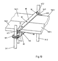
- Fig. 10
- die Anordnung gemäß Fig. 9 in einer Gestaltung, bei der neben den Enden zweier weiterer Gerüstböden ein Überbrückungs- und Abhubsicherungs-Element dargestellt ist, wobei dieses unterseitige Haken aufweist, die in Öffnungen des Horizontal-Tragriegels eingreifen und wobei durch Horizontalverschiebung und Rückschubsicherung unbeabsichtigtes Lösen verhindert werden kann. Die Rückschubsicherung erfolgt in üblicher Weise mit einer Klappe;
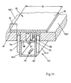
- Fig. 11
- eine vergrößerte Schrägbild-Schnitt-Darstellung eines Überbrückungs- und Abhubsicherungs-Elementes mit Sicherungshaken gemäß Fig. 10;
- Fig. 12
- eine Darstellung eines Horizontal-Tragriegels, bei dem der Zwischenraum zwischen den Gerüstboden-Enden durch eine auf Gerüstbodenhöhe liegende, in das Profil des Horizontalriegels integrierte Fläche dargestellt ist, wobei nur schmale Schlitze zwischen der hutförmigen Erhebung und den Gerüstbodenenden verbleiben, so daß auch nur Teilflächen überdeckende Abhubsicherungsmittel eingesetzt werden können;
- Fig. 13
- das Profil mit den wesentlichen Elementen für einen Horizontal-Trag-Übergangs-Riegel, bei dem auf der einen Seite ein Gerüstboden mit Krallen und auf der anderen Seite ein Gerüstboden mit Durchgangs-Fixieröffnungen für Vertikalstifte aufgelegt werden können, wobei auch für diese Annordnung Überbrückungs- und Abhubsicherungs-Elemente der vorgenannten Art verwendet werden können.
- Fig. 14
- einen Querschnitt durch den Gerüstriegel nach Fig. 8 mit im Anschlußbereich zylindrischen Vertikalstiften;
- Fig. 15
- eine der Fig. 12 entsprechende Darstellung, bei der die Vertikalstifte im Anschlußbereich eingezogen gestaltet sind, so daß sich ein geringerer Stiftabstand bzw. eine größere Tragriegel-Rohr-Breite technologisch günstig realisieren läßt;
- Fig. 16
- ein der Fig. 1 entsprechendes Schrägbild, bei dem eine Konsole auf derselben Ebene wie die zwischen den Stielen liegenden Konsolen-Gerüstböden vorgesehen ist;
- Fig. 17
- ein weiter vergrößertes Teil-Schrägbild der Konsole gemäß Fig. 16, wobei das Ende eines Konsolen-Gerüstbodens und der Anschluß-Übergang zu der Lochscheibe des Vertikal-Stieles dargestellt sind, um die Struktur von Konsole, Konsolen-Gerüstböden und Einhängung zu zeigen;
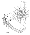
- Fig. 18
- ein teilweise übertrieben vergrößert dargestelltes Teil-Schrägbild der Stütz-Element-Anordnung zur Veranschaulichung der auf die Lochscheibe und den Stiel wirkenden Stützkräfte bei einseitiger Auflage von lastbeanspruchten Konsolen-Gerüstböden auf dem Horizontal-Stützelement bzw. bei einer ungleichmäßigen Lastverteilung der Konsolen-Gerüstböden beidseitig des Stütz-Elementes;
- Fig. 19
- eine Draufsicht auf ein teilweise schematisiertes Gerüstfeld gemäß Fig. 16 mit Gerüstböden beiderseits des Horizontal-Tragriegels und Konsolen-Gerüstböden beiderseits des Horizontal-Stützelementes, wobei zur Überbrückung des Spaltes zwischen den Gerüstböden und den Konsolen-Gerüstböden jeweils ein Überbrückungs-Element vorgesehen ist. Zur Verhinderung des Abhebens sowohl der Gerüstböden und der Konsolen-Gerüstböden als auch der Überbrückungselemente sind gerüst- und konsolenseitig Uberbrückungs- und Abhubsicherungs-Elemente vorgesehen. Diese weisen unterseitige Haken auf, die in Öffnungen des Horizontal-Tragriegels bzw. des Horizontal-Stützelementes eingreifen, wobei durch Horizontalverschiebung und Rückschubsicherung unbeabsichtigtes Lösen verhindert werden kann. Die Rückschubsicherung erfolgt in üblicher Weise mit einer Klappe;
- Fig. 20
- ein Teil-Schnittbild entlang der Schnittkante A-A in Fig. 19, wobei nicht alle Elemente der Konsole dargestellt sind.
- Fig. 21
- einen Teil-Schnitt entlang der Schnittkante B-B in Fig. 19.
- Fig. 1
- A partially schematic oblique view of a scaffold bay with a scaffold floor arrangement provided at a first stand height, with horizontal support bars, the scaffold grid dimensions corresponding to a scaffold system, which usually corresponds to perforated disks on the stems and wedge heads secured by wedges, with the scaffold floors in the corners provided fixing holes are used, which are secured with the help of vertical pins on the edges of the horizontal support bar, as they are otherwise only common with scaffolding systems with a cup-like connection between the horizontal support bar and stem, with a space resulting from the difference in dimensions of existing scaffolding elements the ends of the scaffold floors;
- Fig. 2
- a further enlarged partial oblique view of the horizontal support bar according to FIG. 1, the ends of two scaffolding floors and the connection transition to the perforated disks of the vertical posts are shown to show the structure of the bolt, scaffolding floors and suspension
- Fig. 3
- a partially exaggerated partial oblique view of the support structure element arrangement to illustrate the supporting forces acting on the perforated disc and the handle with one-sided support of load-bearing scaffolding floors on the horizontal support bar or with an uneven load distribution of the scaffolding floors on both sides of the horizontal support bar;
- Fig. 4
- a partially exaggerated partial section of the perforated disc and the wedge head according to FIG 3 in the area of the contact surface on the stem with the supporting forces acting from the wedge head on the perforated disc and on the stem (not shown).
- Fig. 5
- 2 in a design in which, in addition to the ends of two further scaffolding decks, a bridging and lift-off protection element is shown, this having hooks on the underside which engage in openings in the horizontal support bar and wherein unintentional loosening by horizontal displacement and push-back protection can be prevented. The push-back protection is carried out in the usual way with a flap;
- Fig. 6
- an enlarged oblique cross-sectional view of a bridging and lift-off element with safety hook according to FIG. 5;
- Fig. 7
- an oblique view of a bridging and lift-off element with reinforcement double web and corresponding bending reinforcement and locking plate of the horizontal support bar for scaffolding floors on scaffolding according to the preceding figures;
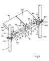
- Fig. 8
- a Schragblld representation of a scaffold element design with two stem parts, four scaffold floors and a scaffold floor support bar with pin lock, the scaffold elements in their longitudinal dimensions are adapted to the scaffold elements of other manufacturers in such a way that horizontal support bars with less, in a the usual dimensions trained design can be used, in which only a narrow slot for the passage of the anti-lift means are provided between the mutually facing ends of the scaffolding floors lying in the longitudinal direction;
- Fig. 9
- a further enlarged partial sectional view of the horizontal supporting bar according to FIG. 8, the ends of two scaffolding decks and the connection transition to the perforated disks of the vertical posts being shown in order to show the structure of the transom, scaffolding decks and suspension;
- Fig. 10
- 9 in a design in which, in addition to the ends of two further scaffolding decks, a bridging and lift-off securing element is shown, this having hooks on the underside which engage in openings in the horizontal support bar and inadvertent release by horizontal displacement and push-back protection can be prevented. The return protection is done in the usual way with a flap;
- Fig. 11
- an enlarged oblique sectional view of a bridging and lift-off element with safety hook according to FIG. 10;
- Fig. 12
- a representation of a horizontal support bar, in which the space between the ends of the scaffolding floor is represented by a surface which is at the level of the scaffolding floor and is integrated into the profile of the horizontal bar, only narrow slots remaining between the hat-shaped elevation and the ends of the scaffolding floor, so that even only partial areas covering anti-lifting devices can be used;
- Fig. 13
- the profile with the essential elements for a horizontal load-bearing transom, in which on one side a scaffold floor with claws and on the other side a scaffold floor with through-fixing openings for vertical pins can be placed, whereby also for this arrangement bridging and anti-lift elements of the aforementioned type can be used.
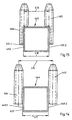
- Fig. 14
- a cross section through the scaffold bolt according to FIG 8 with vertical pins cylindrical in the connection area.
- Fig. 15
- a representation corresponding to FIG. 12, in which the vertical pins are retracted in the connection area, so that a smaller pin spacing or a larger support bar tube width can be realized in a technologically favorable manner;
- Fig. 16
- an oblique image corresponding to Figure 1, in which a console is provided on the same level as the console scaffolding floors lying between the stems;
- Fig. 17
- a further enlarged partial oblique view of the console according to Figure 16, showing the end of a console scaffolding floor and the connection transition to the perforated disc of the vertical stem to show the structure of the console, console scaffolding floors and suspension;
- Fig. 18
- a partially exaggerated partial oblique view of the support element arrangement to illustrate the supporting forces acting on the perforated disc and the handle with one-sided support of load-stressed console scaffolding floors on the horizontal support element or with an uneven load distribution of the console scaffolding floors on both sides of the support element;
- Fig. 19
- 16 with scaffolding floors on both sides of the horizontal support bar and console scaffolding floors on both sides of the horizontal support element, with a bridging element being provided to bridge the gap between the scaffolding floors and the console scaffolding floors. To prevent lifting of the scaffold floors and the console scaffold floors as well as the bridging elements, bridging and lift-off protection elements are provided on the scaffold and console side. These have hooks on the underside which engage in openings in the horizontal support bar or the horizontal support element, wherein unintentional loosening can be prevented by horizontal displacement and push-back protection. The return protection is done in the usual way with a flap;
- Fig. 20
- a partial sectional view along the cutting edge AA in Fig. 19, wherein not all elements of the console are shown.
- Fig. 21
- FIG. 19 shows a partial section along the cutting edge BB in FIG. 19.
Das Gerüst 30 hat Stiele 31.1 und 31.2, die sich in
üblicher Weise auf Anfangsstücken 32.1 und 32.2 abstützen.
Diese wiederum stützen sich auf mit Muttern 33.1 und 33.2
verstellbaren Stützfüßen 34.1 und 34.2. In der üblichen
Weise sind auch als Horizontalstäbe bezeichnete
Horizontal-Längsriegel 35 und Horizontal-Querriegel 36
sowie auch als Diagonalstäbe bezeichnete Diagonalriegel 37
vorgesehen. Diese Gerüstelemente sind in der üblichen Weise
vielfach an dem Gerüst vorgesehen. Zur Abstützung der
Gerüstböden 40.1 ...4 der ersten Gerüstebene 42 ist ein
ungewöhnlich breiter Horizontal-Tragriegel 45 vorgesehen,
welcher mit Hilfe von durch endseitig vorgesehene
Keil-Köpfe 46.1 und 46.2 greifenden Keilen 47.1 und 47.2 an
den Lochscheiben 48.1 und 48.2 der Stiele 31.1 und 31.2 in
der bei solchen Gerüsten üblichen Weise festgekeilt ist.
Diese äußerst stabile und auch gegen Kippkräfte sichere
Verbindung, welche die auftretenden Kräfte mit den
Kopfendflächen unmittelbar in das Stielrohr einleitet, ist
näher anhand der Fig. 3 und 4 veranschaulicht.The
Der Horizontal-Tragriegel 45 hat eine ebene Bodentragplatte
50 sowie endseitige Stift-Tragwände 51.1 und 51.2.
Querverstrebungen 52 unter der Bodentragplatte 50 bilden
ein strukturiertes, biegesteifes Element mit einem im
wesentlichen kastenförmigen Horizontalriegel-Tragrohr 53,
an dessen Enden 54.1 und 54.2 die Keil-Köpfe 46.1 und 46.2
vorzugsweise durch Schweißung befestigt sind. Alle
Bestandteile bestehen in der Regel für die als Massenguter
verwendeten Gerüste aus Stahlblech. Für die besonders
kostenaufwendigen, jedoch für den Schnelltransport sowie
die Schnellmontage und -demontage günstigen Leichtmetallgerüste
können sie auch aus Leichtmetall bestehen.The
Die Gerüstböden 40.1 und 40.2, die in Fig. 2 dargestellt
sind, haben genauso wie die Gerüstböden 40.3 und 40.4 im
Abstand von ihrer kürzeren stirnseitigen Endfläche 55 und
von den Längsseiten-Vertikalflächen 56 in etwa gleichem
Abstand liegende, mit Sicherungs-Löchern bzw. Durchgangs-Fixieröffnungen
57.1 und 57.2 gestaltete Bodenstützmittel.
Diese sind in der Regel mit Vertikalhülsen 58 gestaltet.
Als Gerüstbodenmaterial können Holz, jedoch auch aus Metall
oder Verbundwerkstoffen gebildete, übliche Materialien für
Gerüstböden verwendet werden. Die Abmessungen sowohl der
Gerüstbodenelemente als auch für die Anordnung der
Durchgangs-Fixieröffnungen 57.1 und 57.2 sowie deren
Abstände voneinander und von den Stirn-Flächen der
Gerüstböden entsprechen dem Gerüstsystem, zu dem sie
üblicherweise gehören und die Abmessungen des Horizontal-Tragriegels
sind entsprechend den ansonsten verwendeten
Gerüstbauteilen zu gestalten.The scaffolding floors 40.1 and 40.2 shown in Fig. 2
are just like the scaffolding floors 40.3 and 40.4 in
Distance from its
Mit einem Auflageflächen-Teil 59 liegt das jeweilige
Ende 60 des Gerüstbodens 40 auf der Auflagefläche 61 des
Gerust-Tragriegels 45 bzw. seiner oberen
Bodentragplatte 50, so daß durch einfache Auflage die
Vertikalkräfte übergeleitet werden. Zur Lagesicherung sind
Vertikalstifte 65 vorgesehen. Diese sind an den
Stift-Tragwänden 51.1 und 51.2 außenseitig mit ihren
unteren Befestigungsenden 66 festgeschweißt oder in
sonstiger Weise durch formende Ausbildung ausgeprägt.The respective lies with a
Die freie Aufnahmelänge 67 über der Auflagefläche 61 ist
etwas geringer oder höchstens gleich der Höhe 68 der
Lauffläche 69 des Gerüstbodens 40 über der
Auflagefläche 61. Ihre oberen Enden 70 sind in üblicher
Weise leicht konisch angespitzt, um das Einführen in die
Durchgangs-Fixieröffnungen 57 zu erleichtern. Ihre
Befestigungsenden 66 haben eine Befestigungs-Länge 73, die
entsprechend den üblichen Abmessungen und Gestaltungen eine
fertigungstechnisch günstige und den Kraftverhältnissen
entsprechende Befestigung zuläßt oder die als
Übergangsbereich für eine prägende Ausbildung in einem
spanlosen Formungsverfahren dienen kann.The
Fig. 3 veranschaulicht die Kraftüberleitung von einem,
infolge der Beanspruchung 3, durchgebogenen Gerüstboden 40
auf den Stiel 31. Die relativ paßgenau angeordnete
Vertikalhülse 58 stützt sich im Bereich des oberen Endes 70
des Vertikalstiftes 65 am oberen Stift-Kraftangriffspunkt 6
auf der einen Seite und im Bereich des Befestigungsendes 66
des Vertikalstiftes 65 am unteren Stift-Kraftangriffspunkt
7 auf der gegenüberliegenden Seite ab, so daß ein relativ
großer Stift-Stützabstand 5 zwischen den beiden
entgegengerichtet wirkenden Stift-Stützkräften 8 und 9 des
aufgebrachten Momentes 10 zu betrachten ist.3 illustrates the power transmission from one,
as a result of the stress 3,
Aufgrund der kraft- und formschlüssigen Verbindung zwischen
dem Gerüstboden 40 und dem Vertikalstift 65 kann die
Beanspruchung 3 in ein Moment 1 um die Achse 49 des Keil-Kopfes
46 übergeführt werden. Dieser stützt sich mit seinem
oberen und seinem unteren Kopf-Teil 19 und 20 zum einen in
dem relativ paßgenau gestalteten Horizontalschlitz 24 auf
der Lochscheibe 48 kraftschlüssig und zum anderen über die
mit dem Radius 23 gestaltete, obere und untere
Anlagestützfläche 21 und 22 auf dem Stiel 31 form- und
kraftschlüssig ab.Due to the positive and positive connection between
the
Wie in Fig. 4 gezeigt, stützt sich der obere Kopf-Teil 19
mit seiner oberen Innenbegrenzung 24.1 auf der einen Seite
des Keilkopfes 46 am oberen Lochscheiben-Kraftangriffspunkt
13 mit der oberen Lochscheiben-Stützkraft 11 ab,
während sich auf der gegenüberliegenden Seite des
Keilkopfes 46 der untere Kopf-Teil 20 mit seiner unteren
Innenbegrenzung 24.2 am unteren Lochscheiben-Kraftangriffspunkt
14 mit der unteren Lochscheiben-Stützkraft 12
abstützt. Diese Stützkräfte greifen an der Lochscheibe in
dem wirksamen HorizontalAbstand 4 an.As shown in FIG. 4, the
Aufgrund der bezüglich des Stiels 31 formschlüssigen
Gestaltung (Radius 23) der oberen und unteren
Anlagestützfläche 21 und 22, stützt sich der Keil-Kopf 46
außerdem auf der einen Seite mit seinem oberen Kopf-Teil 19
am oberen Tangentialkraft-Angriffspunkt 17 mit der oberen
tangentialen Kopfteil-Stützkraft ab, während sich auf der
gegenüberliegenden Seite der untere Kopf-Teil 20 am unteren
Tangentialkraft-Angriffspunkt 18 mit der unteren
tangentialen Kopfteil-Stützkraft abstützt. Diese
Stützkräfte greifen in dem wirksamen Vertikal-Abstand 29 am
Stiel 31 an.Because of the positive with respect to the
Neben der Abstützung des Keil-Kopfes 46 an den vorstehend
genannten Auflagestellen, stützt sich dieser noch mit der
oberen, radialen Kopfteil-Stützkraft 25 am oberen
Radialkraft-Angriffspunkt 27 und mit der unteren radialen
Kopfteil-Stützkraft 26 am unteren Radialkraft-Angriffspunkt
28 ab, wobei den beiden Radialkraft-Angriffspunkten
der Abstand 2 zugeordnet ist (Fig. 4).In addition to supporting the
Die besonders vorteilhafte Gestaltung des Keil-Kopfes 46
führt in Verbindung mit den großen wirksamen Abständen der
Stützkraft-Angriffspunkte an der Lochscheibe 48
(Horizontal-Abstand 4) und insbesondere am Stiel 31
(Vertikal-Abstand 2 und Abstand 29) zu einer optimalen
Kraft- und Momentenübertragung auf den Stiel, mit der
Folge, daß größere statische und dynamische Beanspruchungen
ertragbar sind bzw. daß die entsprechenden Gerüstteile
gewichtsoptimiert dimensioniert werden können. The particularly advantageous design of the
Der Horizontal-Tragriegel 45 hat an seiner Unterseite
Ablauf-Öffnungen 84, damit eine Ablaufmöglichkeit für
fluide Medien bei der Oberflächenbehandlung oder für
Regenwasser geschaffen wird.The
Zur Überbrückung des Zwischenraums 76 zwischen den Enden 60
der auf den beiden Seiten des Horizontal-Tragriegels 45
abgestützten Gerüstböden 40.1 ... 4 und zur Verhinderung
ihres Abhebens ist ein Abhubsicherungs-Mittel 95 mit einer
Überbrückungs- und Abhubsicherungs-Platte 80 vorgesehen,
deren Auflageenden 81 mit einer Auflagelänge 82 auf den
Gerüstböden 40.1 ... 4 aufliegen. In der Mitte sind an
ihrer Unterseite Sicherungshaken 85 angebracht, die in
Sicherungsöffnungen 86 mit Langloch-Charakter eingreifen.
Die Hakenenden 87 der Sicherungshaken 85 liegen dann unter
der Stützfläche 88 des Horizontal-Tragriegels 45, wenn die
Überbrückungs- und Abhubsicherungs-Platte 80 in Richtung
der quer zur Längserstreckung des Gerüstbodens verlaufenden
Sicherungsöffnung 86 verschoben ist, so daß es in der
Abhubsicherungs-Position liegt, wie sie sich aus
DE 30 20 389 C2 ergibt. Zur Rückschub-Sicherung können
verschiedene Hilfselemente vorgesehen sein. Besonders
vorteilhaft ist die bekannte Lösung mit einer
Sicherungsklappe 89, die mit Hilfe eines Scharniergelenkes
90 befestigt ist und sich mittels ihres
Schlitzes 91 an der innen liegenden Keilfläche 92 des
jeweililgen Keiles 47 abstützt und so die
Rückschub-Verhinderung in bekannter Weise bewirkt. To bridge the
Eine andere Gestaltung in kinematischer Umkehr bei gleichem
Sicherungsprinzip zeigt die Fig. 7. Hierzu ist zum einen
ein von der Bodentragplatte 50 des Horizontal-Tragriegels
45 aufragendes Biege-Verstärkungs und
Sicherungsblech 93 mit Hakenschlitz 94 und oben liegender
Eingriffs- bzw. Einführungsöffnung 97 vorgesehen. Zum
anderen ist unter der Überbrückungs- und
Abhubsicherungs-Platte 80 eine auch als U-Profil
gestaltbare Doppelsteganordnung 98, mit Aufnahme-Öffnung 99
zur Aufnahme des Sicherungsbleches 93, nach unten
gestaltet, wobei an passenden Stellen
Verschiebe-Sicherungs-Stifte 96 angebracht sind.Another design in kinematic reversal with the same
Fig. 7 shows the security principle
one of the
Auch bei dieser Anordnung können Rückschubsicherungs-Mittel
verschiedener Art, insbesondere mit Hilfe der
Sicherungsklappe 89 vorgesehen sein.With this arrangement, anti-retraction means can also be used
various types, especially with the help of
Die Fig. 8-10 zeigen eine in Aufbau und Anordnung der
Gerüstelemente gleichartige Gestaltung, bei der diese in
ihren Längsabmessungen an die Gerüstelemente anderer
Hersteller derart angepaßt sind, daß Horizontal-Tragriegel
mit geringerer, in einer den üblichen Dimensionen
entsprechend ausgebildeten Gestaltung verwendet werden
können, bei denen nur ein schmaler Zwischenraum 176 für den
Durchgriff des Abhubsicherungs-Mittels 95 zwischen den
einander zugewandten Enden 155 der in Längserstreckung
zueinander liegenden Gerüstböden 140.1 ...4 vorgesehen
sind. Zur Vermeidung des Abhebens der
Gerüstböden 140.1 ...4 ist in an sich gleicher Weise wie in
Fig. 5 und 6 gezeigt, ein Abhubsicherungs-Mittel 95 mit
Überbrückungs- und Abhubsicherungs-Platte 80 vorgesehen.8-10 show a in structure and arrangement of the
Scaffolding elements of the same design, in which these
their longitudinal dimensions to the scaffolding elements of others
Manufacturers are adapted such that horizontal support bars
with less, in one of the usual dimensions
appropriately trained design can be used
can, where only a
Auch diese Gestaltung weist die vorteilhaften Prinzipien von Modulgerüstsystemen mit Lochscheiben und sich mit ihren Stützendflächen an den Rohren der Stiele direkt abstützenden Keil-Köpfen und von oben und unten bezüglich der Scheibe liegenden Keil-Kopfelementen mit durchgesteckten Keilen auf.This design also shows the advantageous principles of modular scaffolding systems with perforated disks and themselves with their Support end faces on the tubes of the stems directly supporting wedge heads and from above and below with respect the wedge head elements inserted wedges.
Eine hinsichtlich der Aufnahme von Kippkräften um die
Gerüstbodenlängsachse verbesserte Gestaltung eines
Horizontal-Tragriegels 245 mit hutartig ausgebildeter
Oberseite zeigt Fig. 12. Der Horizontal-Tragriegel weist
eine obere, Stütz- bzw. Begrenzungsfläche 262 und
beiderseits des Horizontal-Tragriegels 245 tiefer
verlaufende, parallele Auflageflächen 263.1 und 263.2 von
Stift- und Belag-Tragstützen 264.1 und 264.2 auf. Die
Begrenzungsfläche 262 liegt etwa auf derselben Höhe 276 wie
die Oberfläche 277 der Gerüstböden 240.1 und 240.2 so daß
der Abstand 278 der oberen Begrenzungsfläche 262 von der
Auflagefläche 263 in etwa der Dicke 279 der Gerüstböden 240
entspricht. Zwischen der oberen Begrenzungsfläche 262 und
den Auflageflächen 263 sind etwa senkrecht zu diesen
Flächen und parallel zu den Stirnseiten 255 der
Gerüstböden 240 verlaufende Stirn-Begrenzungsflächen 270.1
und 270.2 vorgesehen. Zur Lagesicherung sind im Bereich der
nach außen weisenden Enden 271.2 und 271.2 der horizontalen
Sift- und Belag-Tragstützen 264 sich im wesentlichen nach
oben erstreckende Vertikalstife 265 vorgesehen, die sich
vorteilhafterweise in paßgenauen Durchgangslöchern 272 der
Sift- und Belag-Tragstützen 24.1 und 264.2 erstrecken. Die
Vertikalstifte 265 sind im Bereich ihrer unteren
Befestigungsenden 266 an den Stift- und
Belag-Tragstützen 264 vorzugsweise mittels Schweißen
befestigt. Die freie Aufnahmelänge 267 über der
Auflagefläche 263 ist etwas geringer oder höchstens gleich
der Höhe 268 der Lauffläche der Gerüstböden 240 über der
Auflagefläche 263.One in terms of absorbing tipping forces around the
Longitudinal scaffold floor axis improved design of a
Die übrigen Merkmale des Horizontal-Tragriegels 245
entsprechen im wesentlichen der zuerst beschriebenen
Variante. Es sind in entsprechender Weise Querverstrebungen
252 unter der oberen Begrenzungsfläche 262
vorgesehen, die ein strukturiertes, biegesteifes Element
mit den Stift- und Belagtragstützen 264 und einem im
wesentlichen kastenförmigen Horizontalriegel-Tragrohr 253
bilden, wobei in üblicher Weise an dessen Enden Keil-Köpfe
vorzugsweise durch Schweißung befestigt sind. The remaining features of the
Im Rahmen des zunehmenden Gebrauchs von Modulgerüsten
verschiedener Hersteller und verschiedener Abmessungen
sowie in einzelnen Anschlußbereichen unterschiedlich
gestalteter Gerüstelemente kann es vorkommen oder sinnvoll
sein, einen Teil des Gerüstes mit Gerüstböden 339 zu
versehen, die sich mit endseitig vorgesehenen Klauen bzw.
Krallen 343 auf nach oben offenen Horizontal-Stützschenkeln
344 abstützen, während unmittelbar daneben
mit ihrem Auflageflächen-Teil 359 auf der Horizontal-Auflagefläche
361 aufliegende Gerüstböden 340 mit im
Abstand von Stirn- und Seitenflächen liegenden
Durchgangs-Fixieröffnungen 357.1 und 357.2 vorgesehen sind,
die vorzugsweise mit stützenden, kräfteübertragenden und
gute Benutzungsverhältnisse ermöglichenden
Vertikalhülsen 358 ausgestattet sind. Ein solcher
Horizontal-Tragriegel 345 ist in Fig. 13 mit seinen beiden
verschiedenen Gerüstrahmenböden 339 und 340 und
Anschlußeinrichtungen schematisch dargestellt. An seinem
hinten liegenden Ende 354 ist ein Keil-Kopf 346 des hier
näher beschriebenen Gerüstsystems mit Lochscheiben 348 und
Durchsteckkeilen 347 dargestellt. Hier kann jedoch für
andere Gerüstgrundsysteme auch eine Befestigungseinrichtung
vorgesehen sein, die zum Knotenelement des anderen Gerüstsystems
paßt.As part of the increasing use of modular scaffolding
different manufacturers and different dimensions
and different in individual connection areas
designed scaffolding elements can occur or make sense
be part of the scaffold with
Die Vertikalstifte können im Anschlußbereich zum
Horizontal-Tragriegel hin auf verschiedene Weise gestaltet
sein, um den unterschiedlichen Anforderungen und
konstruktiven Gegebenheiten von Gerüstgrundsystemen
Rechnung zu tragen. Wie in Fig. 14 und 15 dargestellt,
können zum einen im Bereich ihrer Befestigungsenden 464
zylindrisch gestaltete Vertikalstifte 463 vorgesehen sein.
Zum anderen können im Bereich ihrer Befestigungsenden 466
eingezogen gestaltete, vorzugsweise halbzylindrische
Vertikalstifte 465 vorgesehen sein, damit sich ein
geringerer Stiftabstand 416 bzw. eine größere Breite 418
des Horizontal-Riegels 445 mit seinem
Horizontalriegel-Tragrohr 453 technologisch günstig
realisieren läßt. Die Vertikalstifte 463 bzw. 465 sind an
den Stift-Tragwänden 449.1 und 449.2 bzw. 451.1 und 451.2
außenseitig mit ihren unteren Befestigungsenden 464 bzw.
466 festgeschweißt oder in sontiger Weise durch formende
Ausbildung ausgeprägt.The vertical pins can in the connection area
Horizontal support bars designed in different ways
to meet the different requirements and
constructive conditions of basic scaffolding systems
To take into account. As shown in Figs. 14 and 15,
can on the one hand in the area of their fastening ends 464
cylindrical
An der in Fig. 16 vorn liegenden Lochscheibe 48.2 ist eine
Konsole 500 mit einem Keilkopf 46.3 befaßt. Die
Konsole 500 hat ein Horizontal-Stützelement 501, welches
mit einer am Keilkopf-Ende 554.1 befestigten, in etwa
senkrecht zum Horizontal-Stützelement 501 verlaufenden
Vertikalstrebe 502 und einer vom freien Ende bzw. Frei-Ende
554.2 zur Vertikalstrebe 502, insbesondere zu deren
Ende 504 führenden Schrägstrebe 503 ausgestattet ist. Das
Ende 504 der Schrägstrebe 503 liegt an der Außenseite des
Rohres 505 des Stieles 31.2 lose an, während der Keil 47.3
den Keilkopf 46.3 in der üblichen Weise an der Scheibe 48.2
festlegt. Am freien Ende 554.2 des Horizontal-Stützelementes
501 ist ein kurzes Vertikalrohr 506
senkrecht stehend mit einer Schweißnaht 507 befestigt und
hat einen dünneren oberen Rohrteil 508 mit einem
Querloch 509 für das Aufstecken weiterer Gerüstelemente,
inbesondere Stielelemente.At the front in Fig. 16 perforated disc 48.2 is one
Genauso wie die Gerüstböden 140.1 ... 4 haben die Konsolen-Gerüstböden 140.5 und 140.6 in Größe und Anordnung entsprechende Durchgangs-Fixieröffnungen und sind in der üblichen Weise aufgesteckt.Just like the scaffolding floors 140.1 ... 4 they have Console scaffold floors 140.5 and 140.6 in size and arrangement corresponding through-fixing openings and are in the plugged in the usual way.
Auch hier wirkt sich besonders günstig aus, daß der oft
allein große Lasten tragende Konsolen-Gerüstboden 140
insbesondere bei Durchbiegung, sich mit seinen mit
Vertikalhülsen 58 versehenen Durchgangs-Fixieröffnungen 57
an den Vertikalstiften 65 abstützen kann und somit eine
besonders gute Kraftüberleitung vom Konsolen-Gerüstboden
140 auf den Stiel 31 mit Hilfe des Keilkopfes
46 und seiner oberen und unteren Anlagestützflächen 21 und
22 des oberen und unteren Kopfteils 19 und 20 erfolgen kann
(Fig. 18). Der Mechanismus der Kraftüberleitung erfolgt
dabei wie vorstehend am Beispiel eines beanspruchten
Gerüstbodens anhand Fig. 3 und Fig. 4 erläutert. Here, too, the fact that the often
console
Das Horizontal-Stützelement 501 hat eine ebene Bodentragplatte
550 sowie endseitige Stift-Tragwände 551.1 und
551.2. Das Horizontal-Stützelement 501 wird mit einem im
wesentlichen kastenförmigen Stützelement-Tragrohr 553
gebildet, an dessen Keilkopf-Ende 554.1 der Keil-Kopf 46.3
vorzugsweise durch Schweißung befestigt ist. Alle
Bestandteile bestehen in der Regel für die als Massengüter
verwendeten Gerüste aus Stahlblech. Für die besonders
kostenaufwendigen, jedoch für den Schnelltransport sowie
die Schnellmontage und -demontage günstigen Leichtmetallgerüste
können sie auch aus Leichtmetall bestehen.The
Die Konsolen-Gerüstböden 140.5 und 140.6, die in Fig. 20
dargestellt sind, haben genauso wie die
Gerüstböden 140.1 ... 4 im Abstand von ihrer kürzeren
stirnseitigen Endfläche 155 und von den
Längsseiten-Vertikalflächen 156 in etwa gleichem Abstand
liegende Durchgangs-Fixieröffnungen 57.1 und 57.2. Diese
sind in der Regel mit Vertikalhülsen 58 gestaltet. Als
Gerüstbodenmaterial können Holz, jedoch auch aus Metall
oder Verbundwerkstoffen gebildete, übliche Materialien für
Gerüstböden verwendet werden. Die Abmessungen sowohl der
Gerüstbodenelemente als auch für die Anordnung der
Durchgangs-Fixieröffnungen 57.1 und 57.2 sowie deren
Abstände voneinander und von den Stirn-Flächen der
Gerüstböden entsprechen dem Gerüstsystem, zu dem sie
üblicherweise gehören und die Abmessungen des Horizontal-Tragriegels
sind entsprechend den ansonsten verwendeten
Gerüstbauteilen zu gestalten.The console scaffold floors 140.5 and 140.6 shown in Fig. 20
are shown just like that
Scaffolding floors 140.1 ... 4 at a distance from their
Mit einem Auflageflächen-Teil 159 liegt das jeweilige
Ende 160 der Konsolen-Gerüstböden 140.5 und 140.6 auf der
Auflagefläche 561 des Horizontal-Stützelementes 501 bzw.
seiner oberen Bodentragplatte 550, so daß durch einfache
Auflage die Vertikalkräfte übergeleitet werden. Zur
Lagesicherung sind Vertikalstifte 65 vorgesehen. Diese sind
an den Stift-Tragwänden 551.1 und 551.2 außenseitig mit
ihren unteren Befestigungsenden 66 festgeschweißt oder in
sonstiger Weise durch formende Ausbildung ausgeprägt.The respective lies with a
Die freie Aufnahmelänge 67 über der Auflagefläche 561 ist
etwas geringer oder höchstens gleich der Höhe 68 der
Lauffläche 169 der Gerüstböden 140.5 und 140.6 über der
Auflagefläche 561. Ihre oberen Enden 70 sind in üblicher
Weise leicht konisch angespitzt, um das Einführen in die
Durchgangs-Fixieröffnungen 57 zu erleichtern. Ihre
Befestigungsenden 66 haben eine Befestigungs-Länge 73, die
entsprechend den üblichen Abmessungen und Gestaltungen eine
fertigungstechnisch günstige und den Kraftverhältnissen
entsprechende Befestigung zuläßt oder die als
Übergangsbereich für eine prägende Ausbildung in einem
spanlosen Formungsverfahren dienen kann. The
Das Horizontal-Stützelement 501 hat an seiner Unterseite
Ablauf-Öffnungen 584, damit eine Ablaufmöglichkeit für
fluide Medien bei der Oberflächenbehandlung oder für
Regenwasser geschaffen wird.The
Zur Überbrückung des Zwischenraumes 176 zwischen den
Enden 160 der auf den beiden Seiten des Horizontal-Stützelementes
501 abgestützten Konsolen-Gerüstböden 140.5
und 140.6 und zur Verhinderung ihres Abhebens ist ein
Abhubsicherungs-Mittel 595 mit einer Überbrückungs- und
Abhubsicherungs-Platte 580 vorgesehen, deren
Auflageenden 581 mit einer Auflagelänge 582 auf den
Konsolen-Gerüstböden 140.5 und 140.6 aufliegen. In der
Mitte sind an ihrer Unterseite Sicherungshaken 585
angebracht, die in Sicherungsöffnungen 586 mit
Langloch-Charakter eingreifen. Die Hakenenden 587 der
Sicherungshaken 585 liegen dann unter der Stützfläche 588
des Horizontal-Stützelementes 501, wenn die Überbrückungsund
Abhubsicherungs-Platte 580 in Richtung der quer zur
Längserstreckung der Gerüstböden 140.5 und 140.6
verlaufenden Sicherungsöffnung 586 verschoben ist, so daß
es in der Abhubsicherungs-Position liegt, wie sie sich aus
DE 30 20 389 C2 ergibt. Zur Rückschub-Sicherung können
verschiedene Hilfselemente vorgesehen sein. Besonders
vorteilhaft ist die bekannte Lösung mit einer
Sicherungsklappe 589, die mit Hilfe eines
Scharniergelenkes 590 befestigt ist und sich mittels ihres
Schlitzes 591 an der innen liegenden Keilfläche 92 des
jeweiligen Keiles 47.3 abstützt und so die
Rückschub-Verhinderung in bekannter Weise bewirkt.To bridge the
Vorteilhafterweise kann zur Rückschubbegrenzung der
Überbrückungs- und Abhubsicherungsplatte 580 einerends eine
sich überwiegend normal zu ihr erstreckende
Anschlaglasche 520 vorgesehen sein. Zur zusätzlichen
seitlichen Fixierung der Überbrückungs- und
Abhubsicherungsplatte 580, kann diese endseitig eine
überwiegend senkrecht und normal zu ihr verlaufende
Doppelsteg- oder U-Profilanordnung 598 aufweisen.Advantageously, to limit the backfeed
Bridging and anti-lift-
Zur Überbrückung des Zwischenraumes 576 zwischen den
Gerüstböden 140.1 und 140.3 einerseits und den
Konsolen-Gerüstböden 140.5 und 140.6 andererseits, ist
jeweils ein Überbrückungs-Mittel 510 mit
Überbrückungsplatte 511 vorgesehen. Diese weist endseitig
eine Abhub-Fixierungs-Lasche 512 auf, die nach unten
versetzt unter die beiden Überbrückungs- und
Abhubsicherungsplatten 80 und 580 greift. Die Breite 515
der Abhub-Fixierungs-Lasche 512 ist kleiner, und die Breite
der Überbrückungsplatte 511 ist größer als der
Lateralabstand 514 zwischen den Gerüstböden 140.1 bzw.
140.3 und den Konsolen-Gerüstböden 140.5 bzw. 140.6.To bridge the gap 576 between the
Scaffold floors 140.1 and 140.3 on the one hand and the
Console scaffolding floors 140.5 and 140.6 on the other hand
each have a bridging means 510
Die beiden Abhubsicherungsmittel 95 und 595 verhindern
demnach wirkungsvoll nicht nur das Abheben der Gerüstböden
140.1 ... 4 und der Konsolen-Gerüstböden 140.5, 140.6,
sondern auch das Abheben der Überbrückungs-Mittel 510. Prevent the two
Nachfolgend wird ein wichtiger Teil der Beschreibung
wiedergegeben:
Die Erfindung betrifft ein Gerüst (30) bzw. Gerüstteil mit
Tragstruktur-Element-Anordnung, welches ein
verwindungssteifes Raumtragwerk unter Zuhilfenahme von
Stielen (31), Horizontalstäben (35, 36, 45) und
Diagonalstäben (37) bildet, und Modul-Rastermaßen in allen
drei Raumrichtungen sowie Längsanschluß-Rastermaßen für
Standard-Anschluß-Gerüstböden (40.1 bis 40.4) gehorcht. An
Knotenelementen sind Horizontal-Stützelemente bzw.
-Tragriegel (45) mittels je eines Keils (47) über
Keil-Köpfe (46) angeschlossen, wobei diese auf horizontal
angebrachte Lochscheiben (48) der Stiele (31) aufgesteckt
werden. Die Gerüstböden (40) sind auf
Horizontal-Stützelementen bzw. -Tragriegeln (45) zumindest
teilweise mittels an diesen angebrachten Sicherungsstiften
verschiebegesichert und gegen Abheben gesichert abgestützt. An important part of the description is given below:
The invention relates to a scaffold (30) or scaffold part with a support structure element arrangement, which has a torsionally rigid space structure with the aid of supports (31), horizontal bars (35, 36, 45) and
Forms diagonal bars (37), and module grid dimensions in all three spatial directions and longitudinal connection grid dimensions for standard connecting scaffold floors (40.1 to 40.4). Horizontal support elements or
Support bar (45) is connected by means of a wedge (47) via wedge heads (46), which are plugged onto horizontally attached perforated disks (48) of the stems (31). The scaffold floors (40) are open
Horizontal support elements or support bolts (45) are at least partially secured against displacement by means of securing pins attached to them and supported against being lifted off.
- 11
- Momentmoment
- 22
- Vertikal-AbstandVertical distance
- 33
- Beanspruchungdemand
- 44
- Horizontal-AbstandHorizontal Spacing
- 55
- Stift-AbstandPin spacing
- 66
- unterer Stift-Kraftangriffspunktlower Pin-point of force application
- 77
- oberer Stift-Kraftangriffspunktupper Pin-point of force application
- 88th
- untere Stift-Stützkraftlower pin support force
- 99
- obere Stift-Stützkraftupper pin support force
- 1010
- Momentmoment
- 1111
- obere Lochscheiben-Stützkraftupper perforated disc support force
- 1212
- untere Lochscheiben-Stützkraftlower perforated disc support force
- 1313
- oberer Lochscheiben-Kraftangriffspunktupper perforated disc force application point
- 1414
- unterer Lochscheiben-Kraftangriffspunktlower perforated disc force application point
- 1515
- obere tangentiale Kopfteil-Stützkraftupper tangential Headboard supporting force
- 1616
- untere tangentiale Kopfteil-Stützkraftlower tangential Headboard supporting force
- 1717
- oberer Tangentialkraft-Angriffspunktupper point of tangential force
- 1818
- unterer Tangentialkraft-Angriffspunktlower point of tangential force
- 1919
- oberes Kopfteilupper headboard
- 2020
- unteres Kopfteillower headboard
- 2121
- obere Anlagestützflächeupper support surface
- 2222
- untere Anlagestützflächelower support surface
- 2323
- Radiusradius
- 23.123.1
- ""
- 23.223.2
- ""
- 2424
- HorizontalschlitzHorizontal slot
- 24.124.1
- obere Innenbegrenzungupper inner limit
- 24.224.2
- untere Innenbegrenzunglower inner limit
- 2525
- obere radiale Kopfteil-Stützkraftupper radial Headboard supporting force
- 2626
- untere radiale Kopfteil-Stützkraftlower radial Headboard supporting force
- 2727
- oberer Kraft-Angriffspunktupper force point of application
- 2828
- unterer Kraft-Angriffspunktlower force point of application
- 2929
- Abstanddistance
- 3030
- Gerüstframework
- 3131
- Stielstalk
- 31.131.1
- ""
- 31.231.2
- ""
- 32.132.1
- Anfangsstückinitial part
- 32.232.2
- ""
- 33.133.1
- Muttermother
- 33.233.2
- ""
- 34.134.1
- StützfußSupport foot
- 34.234.2
- ""
- 3535
- Horizontal-LängsriegelHorizontal longitudinal bars
- 3636
- Horizontal-QuerriegelHorizontal crossbars
- 3737
- DiagonalriegelDiagonal bars
- 4040
- Gerüstbodenframework floor
- 40.140.1
- ""
- 40.240.2
- ""
- 40.340.3
- ""
- 40.440.4
- ""
- 40.540.5
- Konsolen-GerüstbodenConsole scaffold floor
- 40.640.6
- ""
- 4242
- erste Gerüstebenefirst scaffolding level
- 4545
- Horizontal-TragriegelHorizontal supporting bars
- 4646
- Keil-KopfWedge head
- 46.146.1
- ""
- 46.246.2
- ""
- 46.346.3
- ""
- 4747
- Keilwedge
- 47.147.1
- ""
- 47.247.2
- ""
- 47.347.3
- ""
- 4848
- Lochscheibeperforated disc
- 48.148.1
- Lochscheibeperforated disc
- 48.248.2
- ""
- 4949
- Achseaxis
- 5050
- BodentragplatteSupporting base plate
- 5151
- Stift-TragwandPost supporting wall
- 51.151.1
- Stift-TragwandPost supporting wall
- 51.251.2
- ""
- 5252
- Querverstrebungcross brace
- 5353
- Horizontalriegel-TragrohrHorizontal bar-support tube
- 54.154.1
- Ende von 53End of 53
- 54.254.2
- ""
- 5555
- Endflächeend face
- 5656
- Längsseite-VertikalflächeLongitudinal side vertical surface
- 5757
- Durchgangs-FixieröffnungPassage fixing hole
- 57.157.1
- ""
- 57.257.2
- " "
- 5858
- Vertikalhülsevertical sleeve
- 5959
- Auflageflächen-TeilSupport surfaces part
- 6060
- Ende von 40End of 40
- 6161
- Auflageflächebearing surface
- 6565
- Vertikalstiftvertical pin
- 6666
- Befestigungsendeattachment end
- 6767
- freie Aufnahmelängefree recording length
- 6868
- Höheheight
- 6969
- Laufflächetread
- 7070
- oberes Ende von 65upper end of 65
- 7373
- Befestigungs-LängeMounting length
- 7575
- Abstanddistance
- 7676
- Zwischenraumgap
- 8080
- Uberbrückungs- und AbhubsicherungsplatteBridging and Abhubsicherungsplatte
- 8181
- Auflageendesupport end
- 8282
- AuflagelängeLänge
- 8383
- Gesamtbreiteoverall width
- 8484
- Ablauf-ÖffnungDrain port
- 8585
- Sicherungshakensafety hook
- 8686
- Sicherungsöffnungsecuring aperture
- 8787
- Hakenendehook end
- 8888
- Stützflächesupport surface
- 8989
- Sicherungsklappesafety catch
- 9090
- Scharniergelenkhinge
- 9191
- Schlitzslot
- 9292
- Keilflächewedge surface
- 9393
- Biege-Verstärkungs- und SicherungsblechBending reinforcement and lock washer
- 9494
- Hakenschlitzhook slot
- 9595
- Abhubsicherungs-MittelAbhubsicherungs funds
- 9696
- Verschiebe-Sicherungs-StiftSliding-retaining pin
- 9797
- Einführöffnunginsertion
- 9898
- DoppelsteganordnungDouble web arrangement
- 9999
- Aufnahme-ÖffnungReceiving bore
- 130130
- Gerüstframework
- 140140
- Gerüstbodenframework floor
- 140.1140.1
- ""
- 140.2140.2
- ""
- 140.3140.3
- ""
- 140.4140.4
- ""
- 140.5140.5
- Konsolen-GerüstbodenConsole scaffold floor
- 140.6140.6
- ""
- 145145
- Horizontal-TragriegelHorizontal supporting bars
- 150150
- BodentragplatteSupporting base plate
- 151.1151.1
- Stift-TragwandPost supporting wall
- 151.2151.2
- ""
- 153153
- Horizontalriegel-TragrohrHorizontal bar-support tube
- 154.1154.1
- Ende von 153End of 153
- 154.2154.2
- ""
- 155155
- Endflächeend face
- 156156
- Längsseite-VertikalflächeLongitudinal side vertical surface
- 159159
- AuflageflächenteilSeating portion
- 160160
- Ende von 140End of 140
- 161161
- Auflageflächebearing surface
- 168168
- Höheheight
- 169169
- Laufflächetread
- 175175
- Abstanddistance
- 176176
- Zwischenraumgap
- 184184
- Ablauf-ÖffnungDrain port
- 186186
- Sicherungsöffnungsecuring aperture
- 188188
- Stützfläche support surface
- 240240
- Gerüstbodenframework floor
- 240.1240.1
- Gerüstbodenframework floor
- 240.2240.2
- ""
- 245245
- Horizontal-TragriegelHorizontal supporting bars
- 252252
- Querverstrebungcross brace
- 253253
- Horizontalriegel-TragrohrHorizontal bar-support tube
- 255255
- Stirnseiten von 240End faces of 240
- 262262
- Begrenzungsflächeboundary surface
- 263263
- Auflageflächebearing surface
- 263.1263.1
- Auflageflächebearing surface
- 263.2263.2
- ""
- 264264
- Stift- und BelagtragstützePen and pad support
- 264.1264.1
- Stift- und BelagtragstützePen and pad support
- 264.2264.2
- ""
- 265265
- Vertikalstiftvertical pin
- 266266
- Befestigungsendeattachment end
- 267267
- freie Aufnahmelängefree recording length
- 268268
- Höheheight
- 270.1270.1
- Stirn-BegrenzungsflächeFrontal boundary surface
- 270.2270.2
- ""
- 271.1271.1
- EndeThe End
- 271.2271.2
- ""
- 272272
- DurchgangslochThrough Hole
- 276276
- Höheheight
- 277277
- Oberflächesurface
- 278278
- Abstanddistance
- 279279
- Dicke von 240Thickness of 240
- 339339
- Gerüstbodenframework floor
- 340340
- Gerüstbodenframework floor
- 343343
- Kralleclaw
- 344344
- Horizontal-StützschenkelHorizontal support leg
- 345345
- Horizontal-TragriegelHorizontal supporting bars
- 353353
- Horizontalriegel-RohrHorizontal bar tube
- 354354
- Ende von 353End of 353
- 357357
- Durchgangs-FixieröffnungPassage fixing hole
- 357.1357.1
- Durchgangs-FixieröffnungPassage fixing hole
- 357.2357.2
- ""
- 358358
- Vertikalhülsevertical sleeve
- 359359
- Auflageflächen-TeilSupport surfaces part
- 361361
- Auflageflächebearing surface
- 365365
- Vertikalstiftvertical pin
- 415415
- Stiftabstandpin spacing
- 416416
- Stiftabstandpin spacing
- 417417
- Breite von 423Width of 423
- 418418
- Breite von 453Width of 453
- 423423
- Horizontalriegel-TragrohrHorizontal bar-support tube
- 444444
- Horizontal-TragriegelHorizontal supporting bars
- 445445
- Horizontal-TraoriegelHorizontal Traoriegel
- 449449
- Stift-TragwandPost supporting wall
- 449.1449.1
- Stift-TragwandPost supporting wall
- 449.2449.2
- ""
- 451451
- Stift-TragwandPost supporting wall
- 451.1451.1
- Stift-TragwandPost supporting wall
- 451.2451.2
- ""
- 453453
- Horizontalriegel-TragrohrHorizontal bar-support tube
- 462462
- Breite von 453Width of 453
- 463463
- Vertikalstiftvertical pin
- 464464
- Befestigungsendeattachment end
- 465465
- Vertikalstiftvertical pin
- 466466
- Befestigungsende attachment end
- 500500
- Konsoleconsole
- 501501
- Horizontal-StützelementHorizontal support element
- 502502
- Vertikalstrebevertical strut
- 503503
- Schrägstrebediagonal strut
- 504504
- Ende von 503End of 503
- 505505
- Rohrpipe
- 506506
- Vertikalrohrvertical tube
- 507507
- SchweißnahtWeld
- 508508
- oberes Rohrteilupper tube part
- 509509
- Querlochtransverse hole
- 510510
- Uberbrückungs-MittelUberbrückungs funds
- 511511
- Überbrückungsplattebridging plate
- 512512
- Abhub-Fixierungs-LascheLift-off fixing lug
- 513513
- Breite von 511Width of 511
- 514514
- Lateralabstandlateral distance
- 515515
- Breite von 512Width of 512
- 520520
- Anschlaglaschestop tab
- 550550
- BodentragplatteSupporting base plate
- 551551
- Stift-TragwandPost supporting wall
- 551.1551.1
- Stift-TragwandPost supporting wall
- 551.2551.2
- ""
- 553553
- Stützelement-TragrohrSupporting-support tube
- 554.1554.1
- Kellkopf-Ende von 553Kellkopf end of 553
- 554.2554.2
- Frei-Ende von 553Free end of 553
- 561561
- Auflageflächebearing surface
- 576576
- Zwischenraumgap
- 580580
- Überbrückungs- und AbhubsicherungsplatteBridging and Abhubsicherungsplatte
- 581581
- Auflageendesupport end
- 582582
- AuflagelängeLänge
- 583583
- Gesamtbreiteoverall width
- 584584
- Ablauf-ÖffnungDrain port
- 585585
- Sicherungshakensafety hook
- 586586
- Sicherungsöffnungsecuring aperture
- 587587
- Hakenendehook end
- 588588
- Stützflächesupport surface
- 589589
- Sicherungsklappesafety catch
- 590590
- Scharniergelenkhinge
- 591591
- Schlitzslot
- 595595
- Abhubsicherungs-MittelAbhubsicherungs funds
- 598598
- DoppelsteganordnungDouble web arrangement
Claims (20)
- Scaffold (30) with a load-bearing-structure-element arrangement, it being the case that a torsionally rigid three-dimensional load-bearing structure is formed with the aid of posts (31), horizontal bars (35, 36, 45) and diagonal bars (37), the scaffold (30) conforms to modular unit dimensions in all three directions in space and two longitudinal-connection unit dimensions for the scaffold platforms (40, 140, 240, 339, 340), and that the width unit dimension is selected to correspond to the width of the personnel working space and the height unit dimension corresponds to a modular height dimension for the variable subdivision of a personnel working height, and the longitudinal unit dimension corresponds to the horizontal extent of the size of a scaffold section and the longitudinal-connection unit dimensions, corresponding to the bearing-element configuration, are smaller than the longitudinal unit dimensions, having the following features:a. horizontal load-bearing crossmembers (45, 145, 245, 345, 444, 445), which are supported on the posts (31), are connected to junction elements by means of a wedge (47) in each case;b. the scaffold platforms (40, 140, 240, 339, 340; 140.5, 140.6) are supported on the horizontal load-bearing crossmembers (45, 145, 245, 345, 444, 445);c. platform-supporting means and crossmember bearing means are provided for supporting the scaffold platforms (40, 140, 240, 339, 340; 140.5, 140.6) on the horizontal load-bearing crossmembers (45, 145, 245, 345, 444, 445);d. the scaffold platforms (40, 140, 240, 339, 340; 140.5, 140.6) are prevented from lifting off and are at least partially secured against displacement;e. the horizontal load-bearing crossmembers (45, 145, 245, 345, 444, 445) have at their ends, or at one end, wedge heads (46) with horizontal slots (24) located approximately halfway up for the purpose of plugging onto horizontally arranged perforated discs (48) of the posts (31) and of plugging the wedges (47) through the head parts (19, 20) located above and beneath the associated perforated disc (48) and through the holes in the perforated disc (48) which, in the plugged-in state of the wedges (47), prevent mutual release of the elements without manual intervention;f. the scaffold platforms have cylindrical, vertically extending securing holes (57), at least in part, in the region of their ends;g. vertical pins (65) with dimensions matching the securing holes (57) are arranged on the horizontal load-bearing crossmembers (45, 145, 245, 345, 444, 445);h. the vertical pins (65) are arranged in accordance with the hole spacing and the end-surface spacing of the securing holes (57) provided in the scaffold platforms (40, 140, 240, 340; 140.5, 140.6) and project beyond a top crossmember bearing surface of the horizontal load-bearing crossmember (45, 145, 245, 345, 444, 445);i. the vertical pins (65) project beyond the crossmember bearing surface by way of a free accommodating length (67) which is somewhat less than or at most equal to the thickness of the scaffold platform (40, 140, 240, 340; 140.5, 140.6) and/or its bearing region;j. the perforated borders of the scaffold platforms (40, 140, 240, 340; 140.5, 140.6) are configured as base-supporting surfaces for bearing on the crossmember bearing surface,
characterized by the following features:k. the securing holes (57) have continuous vertical sleeves (58) into which the vertical pins (65) can be introduced in a relatively accurately fitting manner;l. the horizontal load-bearing crossmember (45, 145, 245, 345, 444, 445) has engagement clearances (97) for accommodating at least one lift-off-prevention means (95; 595) covering the ends of the scaffold platforms (40, 140, 240, 339, 340; 140.5, 140.6). - Scaffold according to Claim 1, characterized in that the lift-off-prevention means (95; 595) is configured with a bridging and lift-off-prevention plate (80; 580) which is equipped, on the underside, with vertical spacer parts and horizontal supporting and fixing leg parts.
- Scaffold according to at least either of Claims 1 and 2, characterized in that the lift-off-prevention means (95; 595) is equipped with securing hooks (85; 585) and an end securing flap (89; 589).
- Scaffold according to Claim 2 or 3, characterized in that the supporting and fixing leg parts are designed with at least one displacement-prevention pin (96) which runs essentially horizontally and perpendicularly to the longitudinal axis of the horizontal load-bearing crossmember (45) and engages in a hook-like engagement opening (97) which is open at the top and belongs to the horizontal load-bearing crossmember (45) and/or horizontal supporting element (501).
- Scaffold according to at least one of Claims 1 to 4, characterized in that the horizontal load-bearing crossmember (245) is designed with a supporting surface (262) which is located approximately level with the walking surface (69).
- Scaffold according to Claim 5, characterized in that the bridging and lift-off-prevention plate (80; 580) is a thin sheet-metal or continuous-casting plate which is supported over at least relatively large surface regions of the supporting surface (262) and is equipped with securing hooks (85; 585) for fitting and fixing purposes.
- Scaffold according to at least one of Claims 1 to 6, characterized in that the horizontal load-bearing crossmember (45, 145, 245, 345, 444, 445) has at least one vertical pin-carrying wall (51, 151, 449, 451; 551), on which the vertical pins (65) are fastened.
- Scaffold according to at least one of Claims 1 to 7, characterized in that the vertical pins (65) are arranged on both sides of the horizontal load-bearing crossmember (45, 145, 245, 444, 445).
- Scaffold according to Claim 7 or 8, characterized in that the vertical pins (65) at least partially overlap the pin-carrying wall (51, 151, 449; 551).
- Scaffold according to at least one of Claims 1 to 9, characterized in that the horizontal load-bearing crossmember (45, 145, 245, 345, 444, 445) is configured with a horizontal-crossmember load-bearing tube (53, 153, 253, 353, 423, 453), which has at least one drainage opening (84, 184; 584) for fluid media on its underside.
- Scaffold according to at least one of Claims 1 to 10, characterized in that, in the case of some of the scaffold platforms (340), the platform-supporting means contain vertically extending securing holes (57) in the region of their ends, whereas, in the case of other scaffold platforms (339), said means contain claws (343) in the region of their ends.
- Scaffold according to at least one of Claims 1 to 11, characterized in that, on one side of the horizontal load-bearing crossmember (345), the crossmember bearing means are configured with vertical pins (65) with dimensions matching the securing holes (57) and also with crossmember bearing surfaces (361) for scaffold platforms (340) with securing holes (57), whereas, on another side of the horizontal load-bearing crossmember (345), the crossmember bearing means have crossmember bearing surfaces (341) for scaffold platforms (339) with claws (343).
- Scaffold according to Claim 12, characterized in that the heights of the two crossmember bearing surfaces (341, 361) are co-ordinated with one another such that the walking surfaces of the scaffold platforms (339) with claws and the walking surfaces of the scaffold platforms (340) with securing holes are located approximately at the same level.
- Scaffold according to at least one of Claims 2 to 6, characterized in that, on the. side which is oriented away from the securing flap (589), the bridging and lift-off-prevention plate (580) has a stop lug (520) arranged approximately perpendicularly to the plate plane.
- Scaffold according to at least one of Claims 2 to 6, characterized in that, on the side which is oriented away from the securing flap (589), the lift-off-prevention means (595) has a double-web arrangement (598) running perpendicularly to the plate plane, the spacing between the webs corresponding approximately to the diameter of the posts (31) (Figure 19).
- Scaffold according to at least one of Claims 1 to 15, characterized in that a bridging means (510) formed by a bridging plate (511) is provided for bridging the gap between the bracket-type scaffold platforms (140.5 and 140.6) and the other scaffold platforms (140.1 and 140.3) located opposite.
- Scaffold according to Claim 16, characterized in that the bridging means (510) is configured with a lift-off fixing lug (512) which grips, on the one hand, beneath the lift-off-prevention plate (580) of the lift-off-prevention means (595) and, on the other hand, beneath the lift-off-prevention plate (80) of the lift-off-prevention means (95).
- Scaffold according to Claim 17, characterized in that the bridging means (510) is secured against lateral displacement by means of the lift-off fixing lug (512), which is fitted between the mutually facing, lateral end surfaces of the bracket-type scaffold platforms (140.5 and 140.6) and the other scaffold platforms (140.1 and 140.3) located opposite.
- Scaffold according to at least one of Claims 1 to 18, characterized in that the support for the ends of scaffold platforms which are assigned to a pair of posts (31.1; 31.2), and are located on both sides of the vertical plane common to the two posts, is spaced apart to a considerable extent (spacing 75) such that the bearing on the cantilever parts which are secured in a non-tilting manner on the perforated discs of the posts by means of wedge heads results in a Gerber-beam-like design of the respective storey portion.
- Scaffold according to at least one of Claims 1 to 19, characterized in that the load-bearing-structure-element arrangement is configured with brackets (500) which, instead of the horizontal load-bearing crossmember, each have a horizontal supporting element (501), with a wedge head (46.3) fastened at one end (554.1) with a free end (554.2), with a vertical strut (502) which is fastened at the wedge-head end (554.1), butts against the post (31) and runs approximately perpendicularly to the horizontal supporting element (501), and with a sloping strut (503) running from the free end (554.2) to the vertical strut (502) and with vertical pins (65), which are provided with dimensions matching the securing holes (57) of the scaffold platforms or bracket-type scaffold platforms (140.5, 140.6).
Applications Claiming Priority (2)
| Application Number | Priority Date | Filing Date | Title |
|---|---|---|---|
| DE19511848 | 1995-03-31 | ||
| DE19511848 | 1995-03-31 |
Publications (2)
| Publication Number | Publication Date |
|---|---|
| EP0736648A1 EP0736648A1 (en) | 1996-10-09 |
| EP0736648B1 true EP0736648B1 (en) | 2003-07-16 |
Family
ID=7758266
Family Applications (1)
| Application Number | Title | Priority Date | Filing Date |
|---|---|---|---|
| EP96105043A Expired - Lifetime EP0736648B1 (en) | 1995-03-31 | 1996-03-29 | Scaffold |
Country Status (3)
| Country | Link |
|---|---|
| EP (1) | EP0736648B1 (en) |
| AT (1) | ATE245242T1 (en) |
| DE (2) | DE59610602D1 (en) |
Cited By (3)
| Publication number | Priority date | Publication date | Assignee | Title |
|---|---|---|---|---|
| EP3896240A1 (en) * | 2020-04-15 | 2021-10-20 | RUX GmbH | Scaffolding |
| EP4183951A1 (en) | 2021-11-23 | 2023-05-24 | ALFIX GmbH | Platform securing element, scaffolding and method for securing scaffolding platforms against lifting off |
| DE202023105452U1 (en) | 2023-09-19 | 2023-09-28 | Alfix Gmbh | Deck securing element and scaffolding herewith |
Families Citing this family (3)
| Publication number | Priority date | Publication date | Assignee | Title |
|---|---|---|---|---|
| AU2013101084B4 (en) * | 2013-02-11 | 2015-02-05 | 4 Ken Pty Ltd | Method and system for oblique scaffold connection |
| US10604951B2 (en) * | 2016-11-03 | 2020-03-31 | Alum-A-Pole Corporation | Support member for joinable scaffolding planks |
| CN114541730B (en) * | 2022-03-16 | 2023-11-28 | 山东汇扬自动化设备有限公司 | High-safety climbing frame convenient to disassemble and assemble |
Family Cites Families (7)
| Publication number | Priority date | Publication date | Assignee | Title |
|---|---|---|---|---|
| DE3020389A1 (en) * | 1980-05-29 | 1981-12-03 | geb. Layher Ruth 7129 Güglingen Langer | LIFT SAFETY FOR BUILDING SCAFFOLDINGS |
| US4340130A (en) * | 1980-07-24 | 1982-07-20 | Kwikform America, Inc. | Scaffold frame header |
| DE8513985U1 (en) * | 1985-05-11 | 1985-09-05 | Müller & Borggräfe KG, 5820 Gevelsberg | Plank scaffolding made of vertical frames and decking boards |
| ATE100171T1 (en) * | 1987-09-23 | 1994-01-15 | Geb Layher Ruth Langer | SCAFFOLDING FLOOR PART. |
| DE3824922A1 (en) * | 1988-07-22 | 1990-01-25 | Langer Ruth Geb Layher | Wooden ladder scaffolding with ascent devices |
| DE9311974U1 (en) * | 1993-08-11 | 1993-09-30 | Mafisco Bautechnik Gmbh | Scaffolding element for scaffolding systems to be used in construction |
| DE9417096U1 (en) * | 1994-10-27 | 1995-02-23 | Rux Guenter Gmbh | Stand frame element |
-
1996
- 1996-03-29 DE DE59610602T patent/DE59610602D1/en not_active Expired - Fee Related
- 1996-03-29 DE DE19612537A patent/DE19612537A1/en not_active Withdrawn
- 1996-03-29 EP EP96105043A patent/EP0736648B1/en not_active Expired - Lifetime
- 1996-03-29 AT AT96105043T patent/ATE245242T1/en not_active IP Right Cessation
Cited By (4)
| Publication number | Priority date | Publication date | Assignee | Title |
|---|---|---|---|---|
| EP3896240A1 (en) * | 2020-04-15 | 2021-10-20 | RUX GmbH | Scaffolding |
| EP4183951A1 (en) | 2021-11-23 | 2023-05-24 | ALFIX GmbH | Platform securing element, scaffolding and method for securing scaffolding platforms against lifting off |
| DE102021130655A1 (en) | 2021-11-23 | 2023-05-25 | Alfix Gmbh | Deck securing element, scaffolding and method for securing scaffolding decks against lifting |
| DE202023105452U1 (en) | 2023-09-19 | 2023-09-28 | Alfix Gmbh | Deck securing element and scaffolding herewith |
Also Published As
| Publication number | Publication date |
|---|---|
| DE19612537A1 (en) | 1996-10-02 |
| EP0736648A1 (en) | 1996-10-09 |
| ATE245242T1 (en) | 2003-08-15 |
| DE59610602D1 (en) | 2003-08-21 |
Similar Documents
| Publication | Publication Date | Title |
|---|---|---|
| DE2704398C3 (en) | Framework that can be assembled from uprights and bars | |
| EP0918912B1 (en) | Dismountable facade scaffold | |
| EP0276487B1 (en) | Scaffolding with connecting devices | |
| EP2411598B1 (en) | Scaffold and methods for installing or removing such a scaffold | |
| EP1983129A2 (en) | Support for a space framework and connection device for a railing device and method for fixing a railing device to a support | |
| DE3832066A1 (en) | SCAFFOLDING PART | |
| EP2642045B1 (en) | Overlapping arrangement of at least two gangplanks | |
| EP0116679B1 (en) | Scaffolding, in particular a construction scaffolding | |
| DE19511847A1 (en) | Support structure arrangement for scaffolding | |
| WO2002103136A2 (en) | Dismountable scaffolding | |
| CH657175A5 (en) | System floor shuttering with lowering head | |
| EP0308882B1 (en) | Platform for scaffolds | |
| DE19612867A1 (en) | Scaffolding floor made of longitudinal profiled parts | |
| EP0736648B1 (en) | Scaffold | |
| EP0851075B1 (en) | Elevated platform or staging, particularly for use as floorshuttering for concrete | |
| DE3108020C2 (en) | ||
| DE4027754C3 (en) | Support training for scaffolding floors or the like. With at least one recess in the accessible area | |
| DE3504188A1 (en) | Diagonal strut for scaffoldings | |
| DE820963C (en) | Scaffolding with stands made of tubes | |
| DE4011624A1 (en) | SCAFFOLDING FLOOR | |
| EP3354818B1 (en) | Length alignment assembly for construction scaffolding | |
| EP0268197B1 (en) | Scaffolding, in particular a building scaffolding | |
| EP0331796B1 (en) | Reinforced suspension member for cables | |
| EP0851074B1 (en) | Scaffolding for platform, staging or floorshuttering | |
| EP1134331A2 (en) | Set of elements for a scaffold |
Legal Events
| Date | Code | Title | Description |
|---|---|---|---|
| PUAI | Public reference made under article 153(3) epc to a published international application that has entered the european phase |
Free format text: ORIGINAL CODE: 0009012 |
|
| AK | Designated contracting states |
Kind code of ref document: A1 Designated state(s): AT BE CH DE DK ES FI FR GB IE IT LI LU MC NL PT SE |
|
| 17P | Request for examination filed |
Effective date: 19970128 |
|
| 17Q | First examination report despatched |
Effective date: 19990705 |
|
| RAP1 | Party data changed (applicant data changed or rights of an application transferred) |
Owner name: WILHELM LAYHER VERMOEGENSVERWALTUNGS-GMBH |
|
| RIN1 | Information on inventor provided before grant (corrected) |
Inventor name: LAYHER, ULRICH |
|
| GRAH | Despatch of communication of intention to grant a patent |
Free format text: ORIGINAL CODE: EPIDOS IGRA |
|
| GRAH | Despatch of communication of intention to grant a patent |
Free format text: ORIGINAL CODE: EPIDOS IGRA |
|
| GRAA | (expected) grant |
Free format text: ORIGINAL CODE: 0009210 |
|
| AK | Designated contracting states |
Designated state(s): AT BE CH DE DK ES FI FR GB IE IT LI LU MC NL PT SE |
|
| PG25 | Lapsed in a contracting state [announced via postgrant information from national office to epo] |
Ref country code: NL Free format text: LAPSE BECAUSE OF FAILURE TO SUBMIT A TRANSLATION OF THE DESCRIPTION OR TO PAY THE FEE WITHIN THE PRESCRIBED TIME-LIMIT Effective date: 20030716 Ref country code: IT Free format text: LAPSE BECAUSE OF FAILURE TO SUBMIT A TRANSLATION OF THE DESCRIPTION OR TO PAY THE FEE WITHIN THE PRESCRIBED TIME-LIMIT;WARNING: LAPSES OF ITALIAN PATENTS WITH EFFECTIVE DATE BEFORE 2007 MAY HAVE OCCURRED AT ANY TIME BEFORE 2007. THE CORRECT EFFECTIVE DATE MAY BE DIFFERENT FROM THE ONE RECORDED. Effective date: 20030716 Ref country code: IE Free format text: LAPSE BECAUSE OF FAILURE TO SUBMIT A TRANSLATION OF THE DESCRIPTION OR TO PAY THE FEE WITHIN THE PRESCRIBED TIME-LIMIT Effective date: 20030716 Ref country code: GB Free format text: LAPSE BECAUSE OF FAILURE TO SUBMIT A TRANSLATION OF THE DESCRIPTION OR TO PAY THE FEE WITHIN THE PRESCRIBED TIME-LIMIT Effective date: 20030716 Ref country code: FR Free format text: LAPSE BECAUSE OF FAILURE TO SUBMIT A TRANSLATION OF THE DESCRIPTION OR TO PAY THE FEE WITHIN THE PRESCRIBED TIME-LIMIT Effective date: 20030716 Ref country code: FI Free format text: LAPSE BECAUSE OF FAILURE TO SUBMIT A TRANSLATION OF THE DESCRIPTION OR TO PAY THE FEE WITHIN THE PRESCRIBED TIME-LIMIT Effective date: 20030716 Ref country code: ES Free format text: LAPSE BECAUSE OF FAILURE TO SUBMIT A TRANSLATION OF THE DESCRIPTION OR TO PAY THE FEE WITHIN THE PRESCRIBED TIME-LIMIT Effective date: 20030716 |
|
| REG | Reference to a national code |
Ref country code: GB Ref legal event code: FG4D Free format text: NOT ENGLISH |
|
| REG | Reference to a national code |
Ref country code: CH Ref legal event code: EP |
|
| REG | Reference to a national code |
Ref country code: IE Ref legal event code: FG4D Free format text: GERMAN |
|
| REF | Corresponds to: |
Ref document number: 59610602 Country of ref document: DE Date of ref document: 20030821 Kind code of ref document: P |
|
| PG25 | Lapsed in a contracting state [announced via postgrant information from national office to epo] |
Ref country code: SE Free format text: LAPSE BECAUSE OF FAILURE TO SUBMIT A TRANSLATION OF THE DESCRIPTION OR TO PAY THE FEE WITHIN THE PRESCRIBED TIME-LIMIT Effective date: 20031016 Ref country code: DK Free format text: LAPSE BECAUSE OF FAILURE TO SUBMIT A TRANSLATION OF THE DESCRIPTION OR TO PAY THE FEE WITHIN THE PRESCRIBED TIME-LIMIT Effective date: 20031016 |
|
| NLV1 | Nl: lapsed or annulled due to failure to fulfill the requirements of art. 29p and 29m of the patents act | ||
| PG25 | Lapsed in a contracting state [announced via postgrant information from national office to epo] |
Ref country code: PT Free format text: LAPSE BECAUSE OF FAILURE TO SUBMIT A TRANSLATION OF THE DESCRIPTION OR TO PAY THE FEE WITHIN THE PRESCRIBED TIME-LIMIT Effective date: 20031216 |
|
| GBV | Gb: ep patent (uk) treated as always having been void in accordance with gb section 77(7)/1977 [no translation filed] |
Effective date: 20030716 |
|
| REG | Reference to a national code |
Ref country code: IE Ref legal event code: FD4D |
|
| PG25 | Lapsed in a contracting state [announced via postgrant information from national office to epo] |
Ref country code: LU Free format text: LAPSE BECAUSE OF NON-PAYMENT OF DUE FEES Effective date: 20040329 Ref country code: AT Free format text: LAPSE BECAUSE OF NON-PAYMENT OF DUE FEES Effective date: 20040329 |
|
| PG25 | Lapsed in a contracting state [announced via postgrant information from national office to epo] |
Ref country code: MC Free format text: LAPSE BECAUSE OF NON-PAYMENT OF DUE FEES Effective date: 20040331 Ref country code: LI Free format text: LAPSE BECAUSE OF NON-PAYMENT OF DUE FEES Effective date: 20040331 Ref country code: CH Free format text: LAPSE BECAUSE OF NON-PAYMENT OF DUE FEES Effective date: 20040331 Ref country code: BE Free format text: LAPSE BECAUSE OF NON-PAYMENT OF DUE FEES Effective date: 20040331 |
|
| PLBE | No opposition filed within time limit |
Free format text: ORIGINAL CODE: 0009261 |
|
| STAA | Information on the status of an ep patent application or granted ep patent |
Free format text: STATUS: NO OPPOSITION FILED WITHIN TIME LIMIT |
|
| 26N | No opposition filed |
Effective date: 20040419 |
|
| EN | Fr: translation not filed | ||
| BERE | Be: lapsed |
Owner name: WILHELM *LAYHER VERMOGENSVERWALTUNGS-G.M.B.H. Effective date: 20040331 |
|
| REG | Reference to a national code |
Ref country code: CH Ref legal event code: PL |
|
| PGFP | Annual fee paid to national office [announced via postgrant information from national office to epo] |
Ref country code: DE Payment date: 20050425 Year of fee payment: 10 |
|
| PG25 | Lapsed in a contracting state [announced via postgrant information from national office to epo] |
Ref country code: DE Free format text: LAPSE BECAUSE OF NON-PAYMENT OF DUE FEES Effective date: 20061003 |