EP1983129A2 - Support for a space framework and connection device for a railing device and method for fixing a railing device to a support - Google Patents
Support for a space framework and connection device for a railing device and method for fixing a railing device to a support Download PDFInfo
- Publication number
- EP1983129A2 EP1983129A2 EP08005771A EP08005771A EP1983129A2 EP 1983129 A2 EP1983129 A2 EP 1983129A2 EP 08005771 A EP08005771 A EP 08005771A EP 08005771 A EP08005771 A EP 08005771A EP 1983129 A2 EP1983129 A2 EP 1983129A2
- Authority
- EP
- European Patent Office
- Prior art keywords
- support
- railing
- locking
- holder
- railing device
- Prior art date
- Legal status (The legal status is an assumption and is not a legal conclusion. Google has not performed a legal analysis and makes no representation as to the accuracy of the status listed.)
- Granted
Links
- 238000000034 method Methods 0.000 title claims abstract description 17
- 241001310793 Podium Species 0.000 claims abstract description 23
- 238000003780 insertion Methods 0.000 claims abstract description 17
- 230000037431 insertion Effects 0.000 claims abstract description 17
- 230000000284 resting effect Effects 0.000 claims abstract description 15
- 238000003466 welding Methods 0.000 claims description 33
- 239000002184 metal Substances 0.000 claims description 24
- 229910052751 metal Inorganic materials 0.000 claims description 24
- 238000009434 installation Methods 0.000 claims description 16
- 230000005484 gravity Effects 0.000 claims description 6
- 239000000463 material Substances 0.000 claims description 4
- 238000003825 pressing Methods 0.000 claims description 4
- 230000013011 mating Effects 0.000 claims description 3
- 238000010276 construction Methods 0.000 description 19
- 210000002414 leg Anatomy 0.000 description 6
- 238000004519 manufacturing process Methods 0.000 description 6
- 230000000670 limiting effect Effects 0.000 description 4
- 241000601170 Clematis lasiantha Species 0.000 description 2
- 208000027418 Wounds and injury Diseases 0.000 description 2
- 238000005452 bending Methods 0.000 description 2
- 230000006378 damage Effects 0.000 description 2
- 238000005553 drilling Methods 0.000 description 2
- 208000014674 injury Diseases 0.000 description 2
- 230000007257 malfunction Effects 0.000 description 2
- 230000036961 partial effect Effects 0.000 description 2
- 230000002829 reductive effect Effects 0.000 description 2
- 230000007704 transition Effects 0.000 description 2
- 210000000689 upper leg Anatomy 0.000 description 2
- 240000003517 Elaeocarpus dentatus Species 0.000 description 1
- 241001295925 Gegenes Species 0.000 description 1
- 238000004040 coloring Methods 0.000 description 1
- 238000006073 displacement reaction Methods 0.000 description 1
- 230000001771 impaired effect Effects 0.000 description 1
- 239000007788 liquid Substances 0.000 description 1
- 239000003973 paint Substances 0.000 description 1
- 230000001681 protective effect Effects 0.000 description 1
- 230000000717 retained effect Effects 0.000 description 1
- 230000002441 reversible effect Effects 0.000 description 1
- 238000003860 storage Methods 0.000 description 1
- 239000000725 suspension Substances 0.000 description 1
- 230000008719 thickening Effects 0.000 description 1
Images


Classifications
-
- E—FIXED CONSTRUCTIONS
- E04—BUILDING
- E04G—SCAFFOLDING; FORMS; SHUTTERING; BUILDING IMPLEMENTS OR AIDS, OR THEIR USE; HANDLING BUILDING MATERIALS ON THE SITE; REPAIRING, BREAKING-UP OR OTHER WORK ON EXISTING BUILDINGS
- E04G7/00—Connections between parts of the scaffold
- E04G7/02—Connections between parts of the scaffold with separate coupling elements
- E04G7/06—Stiff scaffolding clamps for connecting scaffold members of common shape
- E04G7/22—Stiff scaffolding clamps for connecting scaffold members of common shape for scaffold members in end-to-side relation
-
- E—FIXED CONSTRUCTIONS
- E04—BUILDING
- E04G—SCAFFOLDING; FORMS; SHUTTERING; BUILDING IMPLEMENTS OR AIDS, OR THEIR USE; HANDLING BUILDING MATERIALS ON THE SITE; REPAIRING, BREAKING-UP OR OTHER WORK ON EXISTING BUILDINGS
- E04G1/00—Scaffolds primarily resting on the ground
- E04G1/14—Comprising essentially pre-assembled two-dimensional frame-like elements, e.g. of rods in L- or H-shape, with or without bracing
-
- E—FIXED CONSTRUCTIONS
- E04—BUILDING
- E04G—SCAFFOLDING; FORMS; SHUTTERING; BUILDING IMPLEMENTS OR AIDS, OR THEIR USE; HANDLING BUILDING MATERIALS ON THE SITE; REPAIRING, BREAKING-UP OR OTHER WORK ON EXISTING BUILDINGS
- E04G5/00—Component parts or accessories for scaffolds
- E04G5/14—Railings
-
- E—FIXED CONSTRUCTIONS
- E04—BUILDING
- E04G—SCAFFOLDING; FORMS; SHUTTERING; BUILDING IMPLEMENTS OR AIDS, OR THEIR USE; HANDLING BUILDING MATERIALS ON THE SITE; REPAIRING, BREAKING-UP OR OTHER WORK ON EXISTING BUILDINGS
- E04G7/00—Connections between parts of the scaffold
- E04G7/30—Scaffolding bars or members with non-detachably fixed coupling elements
- E04G7/302—Scaffolding bars or members with non-detachably fixed coupling elements for connecting crossing or intersecting bars or members
- E04G7/306—Scaffolding bars or members with non-detachably fixed coupling elements for connecting crossing or intersecting bars or members the added coupling elements are fixed at several bars or members to connect
- E04G7/307—Scaffolding bars or members with non-detachably fixed coupling elements for connecting crossing or intersecting bars or members the added coupling elements are fixed at several bars or members to connect with tying means for connecting the bars or members
-
- Y—GENERAL TAGGING OF NEW TECHNOLOGICAL DEVELOPMENTS; GENERAL TAGGING OF CROSS-SECTIONAL TECHNOLOGIES SPANNING OVER SEVERAL SECTIONS OF THE IPC; TECHNICAL SUBJECTS COVERED BY FORMER USPC CROSS-REFERENCE ART COLLECTIONS [XRACs] AND DIGESTS
- Y10—TECHNICAL SUBJECTS COVERED BY FORMER USPC
- Y10T—TECHNICAL SUBJECTS COVERED BY FORMER US CLASSIFICATION
- Y10T29/00—Metal working
- Y10T29/49—Method of mechanical manufacture
- Y10T29/49826—Assembling or joining
- Y10T29/49947—Assembling or joining by applying separate fastener
-
- Y—GENERAL TAGGING OF NEW TECHNOLOGICAL DEVELOPMENTS; GENERAL TAGGING OF CROSS-SECTIONAL TECHNOLOGIES SPANNING OVER SEVERAL SECTIONS OF THE IPC; TECHNICAL SUBJECTS COVERED BY FORMER USPC CROSS-REFERENCE ART COLLECTIONS [XRACs] AND DIGESTS
- Y10—TECHNICAL SUBJECTS COVERED BY FORMER USPC
- Y10T—TECHNICAL SUBJECTS COVERED BY FORMER US CLASSIFICATION
- Y10T403/00—Joints and connections
- Y10T403/30—Laterally related members connected by latch means, e.g., scaffold connectors
Definitions
- the invention relates to a support for a space structure with a fastening device for securing a railing device to the support and a connection arrangement for a railing device comprising at least one support for a space structure and a railing device, which is fastened by means of a fastening device to the support and further relates a method for securing a railing device by means of a fastening device to a support for a space structure.
- a particularly simple fastening construction is for example from CH-A-439 679 known.
- This relates to a scaffolding with vertical support frame, the vertical support tubes are provided with U-shaped Einsteckösen, in which are bent at right angles bent down insertion ends of handrails of railing frame. These railing frames are not secured against lifting upwards, which is not tolerable under safety aspects.
- Another banister attachment is from the FR-A-25 16 141 known.
- scaffolding frames are provided with vertical stems to which transverse bolts extending away are attached. These have at their free ends upwardly projecting cams, so that these bolts form a kind of hook.
- the ends of a double railing or a railing frame are mounted, the upper two end tabs are provided for this purpose with downwardly open receiving openings, which form a kind of contrast hooks.
- the lower two end tabs are provided with elongated holes extending in the vertical direction, of which a slot with a pivotable about a horizontal axis trigger guard against removal in the direction of the bolt of the associated hook one of the scaffolding posts is securable. These railings are also not secured against lifting up.
- the FR-A-25 16 141 also discloses L-shaped longitudinal bars that are used to connect and secure two adjacent scaffold stands on which are supported L-shaped supports formed with a crossbar on which wooden scaffold planks can be supported in an intermediate position between the crossbars of adjacent scaffolding frames ,
- These L-longitudinal bars indicate her L-leg two vertically spaced end legs on and at its from the L-leg perpendicular away from the other end extending a third end leg.
- This third end leg has a downwardly open hook which can be hung on an upwardly open hook bolt of the stems one of the frames.
- the third end leg also has a hook-shaped swivel bracket, which is pivotable about a transverse axis and which pivots under hooks on the hook bolt third end leg by gravity under the hook bolt and in this way allows a vertical lift-off at this end of the L-longitudinal bar.
- this swivel bar is attached to the end of the L-longitudinal bar pivot bracket, an increased risk of injury when handling the L-longitudinal bar.
- a first main group relates to constructions in which the cross-country facilities are frictionally secured by clamping forces against lifting of the supports of the supports.
- this U-shaped wedge boxes are attached to the vertical scaffolding tube stands with their thighs, in which perpendicular bent down tabs of railings are inserted and fixed there by means of a wedge. This must be hit with a hammer to a pressing a tab of a railing against the tube stand or two in the To achieve the same wedge box hinged tabs of two railings against each other and against the pipe stand, so as to secure the handrail or against vertical lifting upwards.
- the wedges To dismantle the framework, the wedges must be knocked out with a suitable tool, so that the construction and dismantling of such scaffolding is comparatively complicated only by means of a tool.
- Such constructions are for example from the DE-A-27 57 189 , of the DE-A-38 32 480 , of the DE-A-31 08 020 , of the DE-A-198 27 284 and the DE-U-20 2004 007 550 known as the "Layher Flash Scaffold System".
- the wedge boxes can also be releasably connectable to the scaffold stems, such as in the WO 02/066765 A2 disclosed.
- a second major group of railing attachment constructions relates to such solutions in which the railings are purely positively connected to the scaffolding posts.
- transverse bolts projecting transversely to their longitudinal axes are fastened to the vertical framework supports for this purpose, on which the railings provided with matching through holes are attached.
- the first subgroup can be divided into two further groups:
- cylinder bolts which have at their free ends a vertical slot in which a Kippstattlasche is pivotally mounted about a horizontal transverse axis.
- the Kippuxlaschen To attach a railing to the scaffold stems the Kippstattlaschen must be transferred to a threading the provided with matching through holes railing tabs on the cylinder bolt enabling unlocking. After threading and attaching the perforated railing tabs the respective Kippstattlasche must be transferred back into a vertical locking position, which is basically gravity-assisted reached by itself.
- a second group of the first subgroup of the second main group relates to similar constructions, which are therefore based on the same basic principle, namely to attach to scaffolding posts transversely projecting bolts on which are fitted with matching through holes railings.
- these constructions such as those from the DE-A-196 33 092 or the EP-A-1 262 611
- no pivotable tilting tabs are used.
- the inner contour of the through holes of the railing and the outer contour of these receiving bolts are designed coordinated so that an attachment of the railing on the bolts only obliquely from below, ie from the underlying scaffold layer, is possible by the railing in an angle of less than 90 degrees to the longitudinal axis of the scaffold stems from below is placed on the bolt.
- FIG. 1 Another construction relating to a railing attachment, which can be assigned to a second subgroup of the second main group, in which the railings are also purely positively connected to the scaffolding stems, is from the DD 90 210 A known.
- a tab on welded to a pipe stem which profiled L-shaped to form a receptacle for vertical Gelanderelfn and bent upwards and is open at the top.
- Through this vertical slot protrudes a nose of a pivotable about a horizontal pivot axis case-latch, which is rotatably mounted on a horizontal bolt.
- the bolt is welded by bridging the vertical slot of the L-strap.
- the case latch To remove the two railing strips or possibly only one of the railing strips, the case latch must be pivoted by hand about its pivot axis upwards in a removal of the respective railing vertical upward enabling release position, whereupon the respective railing vertically upwards from the can be lifted out by the L-strap formedatomicrry.
- a further object of the invention is to provide a support with a fastening device and a connection arrangement which enables advantageous possibilities for installation and removal of a railing device both from the same stand position and from below as leading railing.
- a support in particular a vertical handle, may be provided of metal for a framework, in particular for a facade scaffold, a podium, a staircase or the like space frame, with a fastening device for fastening at least one railing device, in particular a single or double railing, preferably a railing rod, on the support, wherein the fastening device comprises a holder for the railing device, wherein the holder on the support is preferably captive, in particular permanently, for example by welding, fixed, and wherein the holder in a first direction transversely, preferably perpendicularly, to the longitudinal axis of the support extending away therefrom support element having a support position in the horizontal support surface for vertical support of the railing device, wherein the fastening device further comprises a fixed, preferably captive, connected to the support , Preferably with one or as a locking lever designed, locking element having a locking surface for positive, preferably clamping force, locking the rail
- the holder has a fully or completely or essentially completely closed or enclosed through opening for inserting one end of the at least one railing device, in particular of the railing bar, which is at a transverse to the support, preferably parallel to the longitudinal axis of the Support, in particular in their position of use upwards, extending, preferably is integrally connected to the support element, support member of the bracket for lateral support of a support member of the railing device is limited.
- the holder has a fully or completely or substantially fully closed or enclosed passage opening for inserting an end of the at least one railing device, in particular of the or a baluster, having, at a transverse distance to the support, preferably in parallel is limited to the longitudinal axis of the support, in particular in the use position up, extending, preferably integrally connected to the support element, support member of the bracket for laterally supporting a support member of the railing device is not only a simple and inexpensive production, but also a particularly stable design allows the holder, whereby the locking element is particularly stable and secure fastened and storable.
- a through-opening which is "completely or wholly or substantially completely closed or enclosed” can be understood to mean a passage opening which is delimited by wall parts which have one or more, the through-opening in full or completely or essentially completely enclosing form enclosing bodies.
- a support in particular a vertical handle, made of metal for a scaffold, a podium, a staircase or the like space support, be provided with a fastening device for securing at least one railing device, in particular a single or double railing, preferably a baluster, on the support, the mounting device comprising a support for the railing device, the support being permanently affixed to the support, preferably by welding, and the support being in a first direction transverse, preferably perpendicular, to the longitudinal axis of the support extending away from this support element having a support position in the horizontal support surface for vertical support of the railing device, wherein the fastening device further comprises a fixed, preferably captive, connected to the support, preferably with one or as a locking lever designed, locking element with a locking surface for the positive, preferably clamping force-free, locking the railing device against vertical removal of the same in the use position of the support upward
- a particularly simple or easy and secure locking and a particularly simple or easy unlocking or unlocking can be done by an operator.
- the locking element preferably with the aid of a pivot axis containing fastener, in particular a rivet or a pin or pin, in particular a, preferably slotted, dowel pin or a grooved pin, on the support or on the holder, preferably on the Supporting element or not on the holder or not on a part of the holder which contains the receiving element of the holder or not on one or the supporting element of the holder for laterally supporting a support part of the railing device, but on the support or on another part of the support; preferably be attached to a separate, preferably permanently, in particular by welding, preferably spaced from the holder, attached to the support, fastening body.
- fastener in particular a rivet or a pin or pin, in particular a, preferably slotted, dowel pin or a grooved pin
- a support in particular vertical handle, made of metal for a scaffold, a podium, a staircase or the like space support, be provided with a fastening device for securing at least one Railing device, in particular a single or double railing, preferably a railing rod, on the support, wherein the fastening device is a holder for the railing device, wherein the support is permanently affixed to the support, preferably by welding, and wherein the support is a support element extending transversely, preferably perpendicular, to the longitudinal axis of the support in a first direction with a support element in the position of use Support horizontal support surface for vertical support of the railing device, wherein the fastening device further comprises a fixed, preferably captive, connected to the support, preferably designed with one or as a locking lever, locking element with a locking surface for positive, preferably clamping force-free, locking the railing device against vertical
- the holder is a fully or completely or substantially fully closed or enclosed passage opening for inserting one end of the at least one railing device, in particular the chandelierrstabes, having a in a transverse distance to the support, preferably parallel to the longitudinal axis of the support, in particular in the use position upwardly extending, preferably integrally connected to the support member, support member of the bracket for laterally supporting the support member of the railing device limited is.
- This not only allows a simple and inexpensive production but also a particularly stable design of the holder.
- pivot axis transversely, preferably vertically to the longitudinal axis of the support or transversely, preferably perpendicularly, to the first direction.
- pivot axis extends transversely, preferably perpendicular to the longitudinal axis of the support and also transversely, preferably perpendicularly, to the first direction.
- the holder is designed with a in the position of use of the support upwardly open receiving profile for receiving a support member of the railing device, with a in a transverse distance to the support, preferably parallel to the longitudinal axis of the support, in particular in its position of use upwardly extending, preferably integrally connected to the support member and attached thereto, support member of the bracket for laterally supporting the support member of the railing device is formed, wherein between the support member and the support a through hole for receiving the support member of the railing device is formed.
- the receiving profile is designed as a half U, C, or V-profile or as a J-profile or as a U, C, or V-profile.
- the opening edge of the passage opening in the position of use of the support spans a vertical opening plane.
- the holder is designed with or as a bracket, preferably made of a flat material, which has or delimits a passage opening for receiving a support part of the railing device.
- bracket extends in the direction of, preferably parallel to, the longitudinal axis of the support.
- the holder is a stamped, cast or forged part made of metal.
- the locking element or the locking lever by means of a pivot axis containing fastening means, preferably a rivet, on the support or on the holder, preferably on the support element, is fixed.
- the locking element is designed as or with a manually operable or to be actuated, preferably made of plastic or metal, locking lever.
- the locking lever has an actuating part which protrudes in the locking position on the lower position of the support in the position of use of the support. This allows a particularly simple opening or unlocking of the locking lever by hand, especially with a finger of the hand of an operator.
- the locking lever has a, extending from the pivot axis, preferably perpendicular, preferably elongated, operating part. This may have a length which is larger, in particular much larger, than the width of the actuating part or of the locking lever as a whole. In particular, this and optionally in conjunction with a conspicuous coloring of the locking lever, it is clear whether the locking lever is in its locking position and thus whether the hinged there railing device is actually secured or not.
- the locking lever has a, preferably transversely, in particular perpendicular, extending to the pivot axis, longitudinal slot in which in the locking position, a portion of the vertical support member of the holder is added. In this way, the protrusion over the support and also the risk of injury in the locked position is minimized.
- the locking lever and the holder are designed coordinated with each other that the locking lever in the locked position is releasably engaged again on the holder or on a counter body attached to it, so that the locking lever is pivotable only by applying an increased opening force from the locking position to an open position or in the unlocked position.
- the point from which the locking lever is in a secure locking position is made particularly clear to the operator, which is noticeable on the one hand in manual operation by a decrease in the closing force and on the other hand by a clearly audible noise when closing or locking the locking lever is.
- the locking element comprises a pressing body which engages or engages upon pivoting of the locking element from the unlocking position into the locking position with a counter body, the fixed, preferably permanently, on the support or on the holder, preferably at the support member is attached and / or is formed by a part of the support, wherein the Andschreib stresses and the mating body are designed coordinated so that when pivoting the locking element of the unlocking position in the locking position between the Andschreib stresses and the counter body an unintentional unlocking of Locking element obstructing pressure force is formed and / or that in the locking position between the Andschreib redesign and the counter body an inadvertent unlocking of the locking element obstructing pressure force is formed.
- the pressure body and / or the counter body is designed as an eccentric body or are.
- the pressure body is designed as an eccentric eccentric to the pivot axis arranged eccentric body.
- the counter-body is designed as a, preferably cylindrical, pin or bolt which is fixed, preferably non-detachable, to the support or to the holder, preferably to the support member.
- the locking lever has a latching recess, in which engages the latching on the support or on the holder, preferably on the support member, pin or bolt in the locking position.
- the locking lever when pivoting about its pivot axis, preferably upwards, from the closed or locked position into a or the opening or unlocking position is pivotable only by a limited by a stop maximum opening angle which is less than 60 degrees, preferably less than or equal to about 45 degrees. As a result, the risk of people getting stuck on the locking lever in its opening or unlocking position can be reduced.
- the stop with a provided in the region of, preferably upper, end of the holder, preferably integrally connected to the holder nose is formed. This construction is particularly simple and inexpensive realized or produced.
- the locking lever in the, preferably limited by one or the stop maximum, opening or unlocking does not project into one or the insertion of an end of the at least one railing device through opening of the holder.
- the locking lever in the, preferably limited by a stop or the maximum, opening or unlocking the locking lever one or the insertion of an end of the at least one railing device through hole of the holder, the through hole or the opening cross-sectional area thereof is not covered or covered by the locking lever or parts thereof.
- the locking lever in the, preferably limited by one or the stop maximum, opening or unlocking position with one or the Andschreibharmharm on one or attached to the holder, preferably designed as a pin or pin, Opposes opposing body, so that a gravity-induced pivoting of the locking lever is prevented by its pivot axis down. In turn, this ensures that the passage opening of the holder remains free from the locking lever or parts thereof located in the unlocking or opening position.
- the invention also relates to a connection arrangement for a railing device, the at least one support for a scaffold, in particular a facade scaffold, a podium, a staircase or similar space structure, according to at least one of claims 1 to 31 and one, in particular designed as a single or double railing, preferably comprising a handrail device designed with or as a railing rod, which can be fastened to the support with the aid of the fastening device.
- the invention further relates to a connection arrangement for a railing device, the at least one support, in particular a vertical handle, made of metal for a scaffold, in particular a facade scaffold, a podium, a staircase or the like space frame, in particular according to at least one of claims 1 to 31, preferably comprising at least one of the characterizing parts of claims 1 to 31, and at least one, in particular designed as a single or double railing, preferably designed with a handrail or railing, railing device, which is fastened by means of a fastening device to the support, wherein the Support comprises a holder for the railing device, wherein the holder on the support, preferably captive, in particular permanently, for example by welding, and wherein the holder is in a first direction transversely, preferably perpendicular, to the longitudinal axis of the support vo n this path extending support element having a support position in the horizontal support surface for vertical support of the railing device on which, preferably in the region of one end of the railing device or the balus
- the fastening device and the railing device are designed so coordinated that the railing device, although the locking element is in the locking position, in the position of use of the support from below, in particular obliquely from below, on the support surface of the support member of the bracket can be hung or suspended there, and starting from this position can be moved upwards and into an installed position, in which the railing device is secured against removal from the bracket in any directions.
- the holder is designed with a in use position of the support upwardly open receiving profile for receiving a support part of the railing device, in which the support part of the railing device is at least partially received under support on the support surface of the support element, wherein the receiving profile with a is formed at a transverse distance from the support, preferably parallel to the longitudinal axis of the support, in particular in its position of use upwardly extending, preferably integrally connected to the support element and attached thereto support member for laterally supporting the support member of the railing device, wherein between the support element and the support a passage opening for receiving the support part of the railing device is formed, which passes through the passage opening in the position of use of the support horizontally.
- the holder has a completely or essentially completely closed through opening for inserting one end of the at least one railing device, in particular of the railing bar, through which the end of the railing device or of the railing rod is inserted therethrough.
- the passage opening in the position of use of the support as a vertical, extending in the direction, preferably parallel to, the longitudinal axis of the support receiving slot is formed, in which the support part of the railing device, preferably the end of the railing device or the Railing rod, inserted or inserted through it.
- the receiving slot has a height which is greater than the width or the height of at least one end of the ends of the railing device or the railing rod.
- the passage opening has a width which is greater than the thickness or the width of the support part of the railing device. In a preferred embodiment it can be provided that the passage opening has a width which is greater than twice the thickness or width of the support part of the railing device. In this way, at least two railing devices can be placed with their support parts on one and the same holder or hung in one and the same bracket.
- the intended for resting on the support element of the holder ends of the, preferably designed as or with a railing bar, railing device are designed flattened.
- the railing device in the region of at least one end of their, preferably flattened, Ends one in the direction of, preferably parallel to, the longitudinal axis of the end or of the railing rod extending, limited by the support member for resting on the support surface of the support member of the holder and outwardly open first recess which of a transversely, preferably vertically, is limited to the longitudinal axis of the end or the railing rod extending first wall part, in particular a nose.
- a second recess to adjoin the first wall part or the nose in the region of the first recess, the recess extending in the direction, preferably parallel, to the longitudinal axis of the end or of the handrail bar relative to the first one Recess or its support surface recessed bearing surface of the support member and two, preferably parallel, a support surface distance to each other having support surfaces is limited, which extend transversely, preferably perpendicular, to the longitudinal axis of the end of the railing device or the balustrade, wherein the support surface distance is greater than that Width of the support element of the holder in the region of its support surface.
- a defined latching and support point of the railing device is defined on the support element of the holder and there are advantageous possibilities for a positive connection of these elements.
- the support surface distance is approximately 1.5 to 3 times the width of the support element in the region of the support surface.
- the length of the first recess extending in the direction of the longitudinal axis of the end or of the railing rod is greater than the distance measured in the same direction between the support surface of the second recess assigned to the free end of the railing device or railing bar this free end of the railing device or the railing rod.
- the railing rod is designed including its ends as a straight rod, so without the ends would be bent and / or angled. This allows a particularly simple and cost-effective production and a particularly simple and space-saving storage of such a baluster.
- the distance between the bearing surface of the support element and the locking surface of the locking element in the locking position is greater than the, preferably largest, distance between pointing away from the free end of the railing device and the balustrade and the first recess delimiting surface of the first wall portion or the nose and this free end of the railing device or the balustrade, in particular greater than the largest distance between the pointing away from the free end of the railing device or the balustrade and the second recess limiting support surface and this free end the railing device or the railing rod.
- the railing device can also be placed or suspended in or in the support element at or in spite of the locking element located in its locking position from below, in particular from an underlying scaffold position and can then, without the locking element of his Locking position would have to be converted into an open or unlocked position, be pivoted upwards in its horizontal installation or use position, then in this installation or use position already readily secured in any direction attachment of the railing device to the support with positive Secured against vertical lifting is guaranteed upwards.
- the invention also relates to a vertical frame element with at least one support according to at least one of claims 1 to 31 and / or with at least one connection arrangement according to at least one of claims 32 to 48, which additionally according to the subject matter, in particular according to at least one of the claims, of the European patent application No. 06021346.9 or the German utility model application no. 20 2006 015 586.4 is designed.
- the invention further relates to a scaffolding frame, in particular scaffolding frame, with at least one post at least one of claims 1 to 31 and with at least one transverse arm which is at least on the at least one support, preferably captive, in particular permanently, for example by welding, attached.
- the invention further relates to a scaffolding frame, in particular scaffolding positioning frame, with at least one connection arrangement according to at least one of claims 32 to 48, wherein at least one support at least one transverse element, preferably captive, in particular permanently, for example by welding, is attached.
- the invention also relates to a scaffold, in particular scaffolding, preferably a facade scaffold, with at least four vertical supports, to which preferably at least one covering unit, in particular a scaffold floor, horizontal bar elements and / or at least one diagonal element for stiffening the scaffold, are attached, and with at least one support according to at least one of claims 1 to 31 and / or with at least one connection arrangement according to at least one of claims 32 to 48 and / or with at least one vertical frame element according to claim 49 and / or with at least one scaffolding frame according to at least one of claims 50 or 51st
- a scaffold in particular scaffolding, preferably a facade scaffold, with at least four vertical supports, to which preferably at least one covering unit, in particular a scaffold floor, horizontal bar elements and / or at least one diagonal element for stiffening the scaffold, are attached, and with at least one support according to at least one of claims 1 to 31 and / or with at least one connection arrangement according to at least one of claims 32 to 48 and / or with at least one vertical frame element according to
- the invention also relates to a method for fastening at least one railing device by means of a fastening device to a support for a scaffold, in particular a facade scaffold, a podium, a staircase or similar space frame, wherein the fastening device comprises a holder for the railing device, and wherein the holder the support, in particular on a vertical stem, made of metal, in particular according to at least one of claims 1 to 31, preferably with the features of at least one of the characterizing parts of claims 1 to 31, preferably captive, in particular permanently, for example by welding, and wherein the holder is transverse in a first direction, preferably perpendicular to the longitudinal axis of the support extending away therefrom support element with a horizontal position in the use position of the support support surface for vertical supporting, in particular as a single or double railings, preferably with or as a railing bar, preferably a part of a connection arrangement according to at least one of the claims 32 to 48 forming, railing device, wherein on the support surface of the support
- the railing device or the railing rod first in the region of a bearing surface of the first recess of a first end of its or its ends on the support surface of the support member of the first support, preferably after at least one Claims 1 to 31, in particular with the features of at least one of the characterizing parts of claims 1 to 31, preferably in their position of use horizontally, is placed, wherein the locking element of the fastening device of the first support is in its unlocked position, and then the terrain device or the railing rod as long as in the direction of the holder of an adjacent second support, preferably according to at least one of claims 1 to 31, in particular with the features of at least one of the characterizing parts of claims 1 to 31, is displaced until the respective bearing surface of the respective second recess of the two ends of this railing device or this railing rod comes to rest on the respectively associated bearing surface of the respective support element of the respective support to form a positive connection between the railing device and the two supports, and that subsequently the locking elements of
- the invention further relates to a method for attaching at least one railing device by means of a fastening device to a support for a scaffold, in particular a facade scaffold, a podium, a staircase or similar space structure
- the fastening device comprises a holder for the railing device, and wherein the holder the support, in particular on a vertical stem, made of metal, in particular according to at least one of claims 1 to 31, preferably with the features of at least one of the characterizing parts of claims 1 to 31, preferably captively, in particular permanently, for example by welding, and wherein the holder is in a first direction transversely, preferably perpendicular, to the longitudinal axis of the support extending away therefrom support element with a horizontal position in the use position of the support surface for vertical support of, in particular as a single or Doppelge country, preferably with one or as a railing bar, preferably forming part of a connecting arrangement according to at least one of claims 32 to 48, comprising a railing device, wherein on the support surface of
- a method for fastening at least one railing device by means of a fastening device to a support for a scaffold, in particular a facade scaffold, for a podium, a staircase or the like space support structure wherein the fastening device comprises a holder for the railing device, and wherein the holder on the support, in particular on a vertical handle, made of metal, in particular according to at least one of claims 1 to 31, preferably with the features of at least one of the characterizing parts of claims 1 to 31, preferably captive, in particular permanently, for example by welding, is fixed, and wherein the holder is in a first direction transversely, preferably perpendicular, to the longitudinal axis of the support extending away therefrom
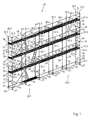
- FIG. 1 Scaffold 20 shown comprises two adjoining vertical scaffolding panels 23.1 and 23.2, each comprising four scaffolding layers or floors 20.1 to 22.4.
- the first framework field shown on the left is constructed from scaffolding positioning frame 21 according to the invention.
- Each scaffold positioning frame 21 consists of two supports 32.1 and 32.2 designed as vertical stems, which are connected to a transverse arm 35 permanently, here by welding, bending and torsion-resistant.
- the transverse arm 35 extends here perpendicular to the longitudinal axes 33 of the two supports 32.1 and 32.2 in the region of their respective upper ends 36.1 and 36.2, so that in the use position 34 downwardly open U- or H-shaped scaffolding frame 21; 21.1, 21.2 is formed.
- the embodiments shown are the scaffolding frame 21; 21.1, 21.2 each designed with a support 32.1 according to the invention, which is designed with a fastening device 38 according to the invention for attaching at least one inventive railing device 28, here in particular in the form of balusters 28.1, 28.2.
- a fastening device 38 for attaching at least one inventive railing device 28, here in particular in the form of balusters 28.1, 28.2.
- Each support 32.1 according to the invention here has two attachment devices 38 arranged in the position of use 34 of the support 32.1 at a vertical distance from each other for the connection of fall protection means in the form of Railing elements 28 on.
- each two substantially parallel railing rods 28.1, 28.2 attached to the fasteners 38 of the outer, respectively wall remote supports 32.1.
- the other or inner stems 32.2 of the frame rack 21 can be placed, for example, in the immediate vicinity of a wall, not shown, for example of a building, so that then on this side of the frame 20, as in FIG. 1 shown that fall protection means or off-road facilities 28 can be omitted.
- Each support 32; 32.1, 32.2; 32.4 of the lowermost scaffold layer or floor 22.1 is here attached to a so-called initial piece 27, which is usually designed with an upwardly pointing pipe socket.
- the inner diameter of this pipe socket is slightly larger than the outer diameter of the lower ends 37.1, 37.2 of the supports 32; 32.1, 32.2, 32.4, so that the supports 32; 32.1, 32.2, 32.4 can each be inserted into one of these pipe sockets of the starting pieces 27.
- the starting pieces 27 are usually provided with a spindle and a spindle nut screwed thereon, whereby a height or level adjustment of the supports 32; 32.1, 32.2; 32.4 can be achieved.
- Each start piece 27 here has a perforated disc 30, which is provided with openings.
- connection heads horizontal rod elements 24, 25, in particular longitudinal and cross bars bars, to the pipe socket. These connection points are also referred to as connection nodes 29, 29 '.
- rod elements usually longitudinal latch 24 and crossbar 25 are used.
- the longitudinal bars 24 and the cross bar 25 are in each case wedged in pairs to the pipe socket of the starting pieces 27 that two parallel longitudinal bars 24 and two perpendicular thereto, but with each other parallel cross bars 25, a stable rectangular base frame is constructed. Starting from this then built in a substantially horizontal plane base frame then the framework 20 is built up.
- the supports 32; 32.1, 32.2, 32.3, 32.4, 32.5 are usually designed as tubes.
- On or at the transverse arms 35; 35.1, 35.2 of the frame rack 21; 21.1, 21.2 can covering units, preferably in the form of scaffold floors 31, are attached, which are provided with running and / or work surfaces and which limit the respective floor or scaffold layer 22.1, 22.2, 22.3, 22.4 downwards and upwards horizontally.
- railing bars 28.1 and 28.2 provide a longitudinal fall protection protection, are here on the narrow lateral sides perpendicularly extending side railing 28.3 between the supports 32.1 and 32.2 of the scaffolding rack 21 according to the invention attached, as in FIG. 1 shown on the left outside.
- second framework field 23.2 is constructed with scaffolding elements of a modular framework of the so-called Layher Allround modular scaffold system.
- This comprises separate, designed as vertical stems support 32.4, which are provided in the longitudinal direction with a number of spaced in a same grid spacing perforated discs, here with four perforated discs.
- longitudinal latch 24 and Cross bar 25 and optionally not shown diagonal bar with the help of known wedge connecting heads 275 wedged.
- two of these stems 32.4 are connected in the region of their upper ends with a horizontal bar element 25, which is typically a round bar or an upwardly open U-profile bar.
- pad units in the form of scaffold floors 31 can be hung or suspended directly or preferably via hooks.
- the distance of the top hole 30 in the position of use of the respective handle 32.4 from the lower end thereof corresponds to the distance between the perforated disks 30 fixed to the supports 32.1 and 32.2 of the inventive scaffold setting frame 21 in the region of their upper ends 36.1, 36.2 from the lower ends 37.1, 37.2 thereof Supports 32.1, 32.2.
- a scaffold or a scaffold field 23.1 with the scaffold positioning frame 21 according to the invention; 21.1, 21.2 or with supports 32 according to the invention; 32.1, 32.2 is formed to connect seamlessly with a scaffold or a framework field 23.2 of a modular scaffolding, so that a step-free transition between the pad units or scaffold floors 31 of the first frame field 23.1 with the pad units or scaffold floors 31 of the second frame field 23.2 is possible.
- the railing bars or railing bars 28.4 of the modular scaffolding forming the second scaffolding field 23.2 are directly in the region of the fastening devices 38 according to the invention of the supports 32 according to the invention; 32.1, 32.2 attached, for example by means of clampable perforated discs.
- the balusters 28.1, 28.2 of the first frame field 23.1 are arranged, for example, slightly above the balusters 28.4 of the second frame 23.2 of the modular frame, whereby this vertical distance is only so small that it neither the use nor the safety of a "combination frame" constructed in this way. impaired.
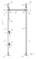
- FIG. 2 is a first embodiment of a scaffolding frame according to the invention 21.1 shown.
- This consists of two parallel and arranged in a plane supports 32.1, 32.2, which are formed and arranged in the position of use 34 as vertical stems.
- a perforated disc 30 which are designed in a known manner with breakthroughs for wedging provided with connecting heads with a wedge scaffolding elements.
- These perforated discs 30 here comprise the respective stem tube of the respective support 32.1, 32.2 in full circumference.
- the upper ends 36.1, 36.2 of the supports 32.1, 32.2 are each formed with a pipe connector 54.1, 54.2, whose outer diameter is slightly smaller than the inner diameter of the lower ends 37.1, 37.2 of the supports 32.1, 32.2. In this way, a plurality of such supports 32.1, 32.2 or positioning frame 21, as in FIG. 1 shown, put on each other.
- This cross arm 35.1 is formed here with a round tube, which is preferably connected at its two ends in one piece with wedge-shaped to the stem and pulley center tapered connecting heads 75.1 and 75.2. This connection heads or at least one of them is or are preferably produced by forming the round tube.
- This scaffold positioning frame 21.1 is formed with a vertical frame element 105.1, which is designed with the one support 32.1 and the thereto permanently, preferably by welding, fixed cross arm 35.1.
- European patent application no. 06021346.9 and German Utility Model Application No. 20 2006 015 586.4 be referenced, whose content is included in full at this point for the sake of simplicity, so that therefore the entire disclosure content of these two patent applications is also the subject of the invention described herein.
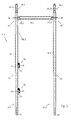
- FIG. 3 shows a second embodiment of a scaffolding frame according to the invention 21.2 shown. This differs from the one in FIG. 2 shown scaffolding frame 21.1 exclusively by the shape of the transverse arm and its detailed connection to the two supports 32.1 and 32.2, so that reference is made with respect to the remaining details to the above statements to the scaffolding frame 21.1 can be. Accordingly, in FIG. 3 the same elements with the same reference numerals as in FIG. 2 ,
- the cross arm 35.2 of in FIG. 3 shown scaffolding frame 21.2 is formed with an upwardly open U-profile tube or U-cross bar 35.2. This or this is connected at its two ends here in one piece with a pinch profile connection head 175.1, 175.2. These connection heads 175.1, 175.2 or at least one of them is or are preferably produced by forming the U-profile tube. Each of these connection heads 175.1 and 175.2 in turn has a horizontal Aufsteckschlitz, by means of which the respective connection head 175.1, 175.2 attached to the respective perforated disc 30 of the respective support 32.1, 32.2 and there again with both the perforated disc and with the stem to a bending and torsionally stiff, downwardly open U- or H-shaped frame rack 21.2 is welded.
- Each of the scaffolding frame 21 according to the invention; 21.1, 21.2 thus has at least one inventive support 32.1 made of metal, which is designed in particular as a vertical handle for a frame 20, in particular a facade scaffold, a podium, a staircase or the like space structure.
- the support 32.1 according to the invention has a fastening device 38 according to the invention for fastening at least one railing device 28, in particular a single or double railing, preferably a railing rod 28.1, 28.2 on the support 32.1.
- This fastening device 38 has a holder 40 for the railing device 28.
- the holder 40 is permanently connected here by welding to the support 32.1.
- the holder 40 has a transverse direction in a first direction 41, preferably perpendicular to the longitudinal axis 33 of the support 32.1 extending away from this support element 42 having a in use position 34 of the support 32.1 horizontal bearing surface 43 for vertical support of the railing device 28.
- the fastening device 38 also has a, preferably captive, connected to the support 32.1, here designed with one or as a locking lever 70, locking element 45 with a locking surface 46; 46.1, 46.2 for positive locking, preferably clamping force-free locking of the railing device 28 against vertical removal of the same in the use position 34 of the support 32.1 upwards in a locking position 47.
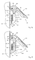
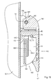
- the locking element 45 is pivotable about a pivot axis 50 from an opening or unlocking position 48 (FIG. FIGS. 4 and 5 ), preferably manually, into a locking position 47 (FIG. FIGS. 1 . 2 . 3 and 6 ), here in the use position 34 of the support 32.1 down, pivot.
- the locking surface 46 of the locking element 45 of the support surface 43 of the support member 42 is opposite.
- the locking surface 46 is arranged in the locking position 47 and in the use position 34 of the support 32.1 at a vertical distance 51 above the support surface 43 of the support element 42.
- the pivot axis 50 extends perpendicular to the longitudinal axis 33 of the support 32.1 and also perpendicular to the first direction 41, with which the support member 42 extends away from the support 32.1.
- the holder 40 has a completely closed passage opening 57 for insertion of an end 58.1, 58.2 of the at least one railing device 28, in particular of the railing rod 28.1, 28.2, which, at a transverse distance 59 to the support 32.1, here parallel to the longitudinal axis 33rd the support 32.1 in its position of use 34 upwardly extending, here integrally attached to the support member 42 support member 44 of the bracket 40 for laterally supporting the support member 56 of the railing device 28 is limited (see in particular FIGS. 4 to 6 ).
- the opening edge 61 of the passage opening 57 which here is formed with the U-shaped profile and designed as a bracket 65 holder 40 on the one hand and the outer surface of the support 32.1 on the other hand, clamped in the position of use 34 of the support 32 to a vertical opening plane, here the longitudinal axis 33 of the support 32.1 contains. Accordingly, the passage opening 57 in the position of use 34 of the support 32.1 here as a vertical, in the direction parallel to the longitudinal axis 33 of the support 32.1 extending receiving slot 63 designed.
- the holder 40 is designed with a bracket 65 made of flat material, which is a stamped part here, but which may also be designed in particular as a cast or forged part made of metal.
- This bracket 65 thus has the designed as a receiving slot 63 Through hole 57 for receiving the support member 56 of the railing device 28 on or limits this passage opening 57.
- the bracket 65 is arranged parallel to the longitudinal axis 33 of the support 32.1 and its legs are welded to the support 32.1.
- the locking element 45 is here designed with a manually operable locking lever 70 which is fixed here on the in use position 34 of the support 32.1 upper leg of the holder 40 by means of a here designed as a rivet 66 and the pivot axis 50 containing fastener.
- the locking lever 70 is preferably made of plastic.
- the locking lever 70 has a perpendicular to the pivot axis 50 extending longitudinal slot 71, in which in the locking position 47 of the locking lever 70, a majority of the vertical support member 44 of the holder 40 and the bracket 65 is added.
- the locking lever 70 consists of a pivoting and locking part 62 and an integrally connected thereto actuating part 60.
- the latter tapers concavely rounded towards its free end, in this way an advantageous attacking with a finger of a hand of an operator, for Purpose of a simple transfer of the locking lever 70 from its locking position 47 to reach up to its unlocking or in an open position 48.
- the articulation and locking part 62 of the locking lever 70 comprises an opening contained in the mounting position, the pivot axis 50, through which a part of the rivet 66 is inserted therethrough.
- the articulation and locking part 62nd further comprises a formed as an eccentric body 76 Andschreibharm 72 which engages upon pivoting of the locking lever 70 from the unlocked position 48 in the locking position 47 with a here formed as a cylindrical pin 77 counter body 73 engages or is engaged.
- the mating body 73 is fixed, preferably permanently, to the support member 44 so as to extend beyond both sides of the side surfaces of the bracket 65.
- the longitudinal axis 78 of the pin 77 is perpendicular to the longitudinal axis 33 of the support 32.1 and arranged parallel to the pivot axis 50.
- the longitudinal axis 78 of the pin 77 further extends perpendicular to the first direction 41, with which the support element 42 extends away from the support 32.1.
- the pressure body 72 of the locking lever 70 is designed as an eccentric to the pivot axis 50 arranged eccentric 76.
- the locking lever 70 in the region of its transition between the actuating part 60 and the articulation and locking part 62 has an outwardly adjoining the eccentric body 76 locking recess 79, in which the attached to the support member 44 of the holder 40 Pin 77 engages latching in the locking position 47.
- the invention also relates to a connection arrangement for a railing device 28, the at least one support 32.1 for a framework 20, in particular a facade scaffold, a podium, a staircase or the like space structure and one in particular designed as a single or double railing, preferably with one or as a railing rod 28.1, 28.2 designed railing device 28 includes, which is fastened by means of the fastening device 38 to the support 32.1.
- the locking surface 46 of the locking element 45 is in the locking position 47 of the support surface 43 of the support member 42 and the locking surface 46 is in the locking position 47 and in the use position 34 of the support 32.1 at a vertical distance 51 above the support surface 43 of the support member 42nd arranged, which is greater than the height 67 of resting on the support surface 43 of the support member 42 of the holder 40 support member 56 of the railing device 28.
- the invention also includes a connection arrangement 80 for a railing device 28, the at least one inventive support 32.1, in particular a vertical handle, made of metal, for a frame 20, in particular a facade scaffold, a podium, a staircase or the like space frame and at least one, especially as Single or double railing designed, preferably with or as a railing rod 28.1, 28.2 designed railing device 28 which is fastened by means of a fastening device 38 to the support 32.1, wherein the support 32.1 comprises a holder 40 for the railing device 28, wherein the holder 40th , Preferably captive, in particular permanently, for example by welding, is connected or attached to the support 32 and wherein the holder 40 in a first direction 41 transversely, preferably perpendicular to the longitudinal axis 33 of the support 32 away from the latter extending support member 42 with an i n use position 34 of the support 32.1 horizontal supporting surface 43 for vertical support of the railing device 28, on which a, preferably in the region of an end 58.1, 58.2
- the fastening device 38 and the railing device 28 are designed coordinated so that the railing device 28, although the locking element 45 is in the locking position 47, in the use position 34 of the support 32 from below, in particular obliquely from below, on the support surface 43 of Support member 42 of the holder 40 can be placed or can be hung there, and starting from this position can be pivoted upwards and into a mounting position 49, in which the railing device 28 is secured against removal from the holder 40 in any direction.
- the holder 40 has a fully closed passage opening 57 in the form of a receiving slot 63 for insertion of an end 58.1, 58.2 of the at least one railing device 28 and the railing rod 28.1, 28.2, through which the end 58.1, 58.2 of the railing device 28 and des Railing rod 28.1, 28.2 is inserted through (see. Figures 5 and 6 ).
- the passage opening 57 is, in the position of use 34 of the support 32, designed as a vertical parallel to the longitudinal axis 33 of the support 32 extending receiving slot 63, in which the support member 56 of the railing device 28, here the end 58.1, 58.2 a balancing rod 28.1, 28.2 or both railing rods 28.1, 28.2, inserted or pushed through ( Figures 5 and 6 ).
- the receiving slot 63 has a height 68 which is greater than the width or the height 67 of at least one end 58.1, 58.2 of the ends 58.1, 58.2 of the railing device 28 or of the railing rod 28.1, 28.2. Further, the passage opening 57 has a width 59 which is greater than the thickness or width 82 of the support member 56 of the railing device 28 and the railing rod 28.1, 28.2.
- the passage opening 57 has a width 59 which is slightly larger than twice the thickness or width 82 of the support member 56 of the railing device 28 or of the railing rod 28.1, 28.2, so that in the holder 40 so up to two such railing devices 28, 28 or railing rods 28.1, 28.2 can be suspended and locked by means of the locking lever 40.
- the railing device 28 has in the region of at least one end 58.1, 58.2, in this case in the region of its two flattened ends 58.1, 58.2, in each case one extending parallel to the longitudinal axis 83 of the end 58.1, 58.2 or the railing rod 28.1, 28.2, with the support part 56th for resting on the bearing surface 43 of the support element 42 of the holder 40 inwardly limited, and outwardly, respectively transversely or perpendicular to the longitudinal axis 83 of the railing device 28 open first recess 86.
- first wall portion 87 extending transversely, here approximately perpendicular to the longitudinal axis 83 of the end 58.1, 58.2 or the railing device 28, in this case the railing rod 28.1, 28.2, which here is delimited in the form of a hook-shaped nose 88.
- the first recess 86 is bounded in the direction of the longitudinal axis 83 by two spaced-apart wall parts 87 and 89.
- the wall portion 89 is concavely rounded (at 91) and the nose 88 limiting wall portion 87 is provided with an insertion 92nd designed.
- a second recess 94 adjoins the first wall part 87 or the nose 88. This is limited by a parallel here to the longitudinal axis 83 of the railing device 28 and the railing rod 28.1, 28.2 extending and recessed relative to the first recess 86 bearing surface 95 of the support member 56 and two, here parallel, a support surface spacing 98 to each other having support surfaces 97.1, 97.2 limited.
- These support surfaces 97.1, 97.2 here extend perpendicular to the longitudinal axis 83 of the end 58.1, 58.2 or the railing device 28 or the railing rod 28.1, 28.2.
- the support surface spacing 98 of these support surfaces 97.1, 97.2 is greater than the width 99 of the support element 42 of the support 40 in the region of the support surface 43 of the support element 42, so that the railing device 28, respectively the respective railing rod 28.1, 28.2, there with its second recess 94 positively can engage.
- the support surface distance 98 is preferably about 1.5 to 3 times the width 99 of the support element 42 in the region of the support surface 43, so that manufacturing and in particular installation tolerances can be compensated so that it is always ensured that the railing device 28 and the Railing rod 28.1, 28.2, in each case reliably and safely in the region of its or its two ends 58.1, 58.2 in each case a holder 40 of a support 32.1 according to the invention can be mounted in installation or use position 49.
- the length 93 of the first recess 86 extending in the direction of the longitudinal axis 83 of the end 58.1, 58.2 or of the railing rod 28.1, 28.2 is much larger than the first measured in the same direction distance 100 between the free end 101 of the respective end 58.1, 58.2 of the railing device 28 and the baluster 28.1, 28.2 associated support surface 97.2 of the second recess 94 and this free end 101 of the railing device 28 and the railing rod 28.1, 28.2.
- connection arrangement is also that the distance 51 between the support surface 43 of the support element 42 and the locking surface 46 of the locking element 45 in the locking position 47 is greater than the largest distance between the of the free end 101 of the railing device 28 and the railing bar 28.1, 28.2 pointing away and the first recess 86 delimiting surface 90 of the first wall portion 87 and the nose 88 and this free end 101 of the railing device 28 and the railing rod 28.1, 28.2, in particular greater than the largest distance 102 between the from the free end 101 of the railing device 28 and the railing rod 28.1, 28.2 pointing away and the second recess 94 limiting support surface 97.2 and this free end 101 of the railing device 28 and the railing rod 28.1, 28.2.
- a second embodiment of a support or fastening device according to the invention for fixing railing devices is with his or her parts in the FIGS. 11 to 18 illustrated.
- the same parts are denoted by the same reference numerals with respect to the previously discussed embodiments.
- the holder 140 and the bracket 165, the locking element 145 and the locking lever 170, the fixing means containing the pivot axis 50 66 and also the railing device 128; 128.1, 128.2 slightly differently designed than the previously described parts 40 and 65, 45 and 70, 166 and 28; 28.1, 28.2.
- the fastening means and / or the railing device can also be designed the same, as in the embodiments described above.
- FIGS. 12a to 12d and 13a to 13f The exact design of the locking lever 170 acting as a locking element 170 according to the second embodiment is particularly in the FIGS. 12a to 12d and 13a to 13f shown.
- This embodiment differs from that in particular in the FIGS. 7a to 7d and 8 a to 8 f shown in the first embodiment in that in the open position 48 the handle 32.1 facing region of the articulation and locking member 162 between the pivot axis 50 and the locking surface 46; 46.1, 46.2 a here approximately rectangular limited recess 210 is provided.
- the inner contour of this recess 210 corresponds to the inner contour of the passage opening 57 of the holder 140 in the region of its upper end. This leads into the in FIG.
- the shape or contour of the Andschreib stresses 172 is slightly changed in the locking lever 170 compared to the locking lever 70.
- the Andschreib stresses 177 is now designed such that it, as in FIG. 16 shown in the said or desired open position 48 abuts against the designed as a pin counter body 73. In this way, a gravity-induced (further) pivoting of the locking lever 170 is prevented in this open position 48 down.
- the Andschreibêt stresses 172 is no longer designed here as an eccentric body.
- the Andschreibharmharmharm 172 is designed in this embodiment with a convexly outwardly curving Andschreibwand which is separated from a slot 85 of the remaining rear part of the articulation and locking member 162.
- the Andschreib stresses 172 in the course of a deliberate manual pivoting of the locking lever 170 of the in the Figures 11 . 16 and 17 shown opening or unlocking position in the in FIG. 18 shown locking or locking position 47 are pressed back resiliently under exercise of a certain pivoting force so that it can pass through the acting as a counter-body 73 pin 77.
- this second embodiment further measures are provided in this second embodiment, by which it is ensured that the Locking lever 170, viewed from its closed or locking position 47, only by a certain maximum opening angle 265 about its pivot axis 50 can be pivoted upwards.
- this maximum opening angle 265 is less than about 60 degrees, in particular less than or equal to about 45 degrees (see in particular FIG. 17 ).
- this maximum opening angle 265 is less than about 60 degrees, in particular less than or equal to about 45 degrees (see in particular FIG. 17 ).
- the locking lever 170 has a stopper body 209 which extends horizontally between the separated by the longitudinal slot 71 bearing bodies 208.1 and 208.2. Furthermore, it is provided that the holder 140 has at its upper end a nose 206 which forms a stop 207 for the stop body 209 of the locking lever 170 or its outer surface facing away from the handle 32.1 ( FIG. 17 ).
- the stop 207 of the holder 140 and the stop member 209 of the locking lever 170 are designed coordinated so that the locking lever 170, as mentioned above, only about a certain maximum opening angle 265 about its pivot axis 50 can be pivoted upward, here about 45 degrees is.
- the locking lever 170 is no longer fastened and supported on the holder 140 with the aid of a rivet acting as a fastening means but now with the aid of a pin 166 which likewise functions as a fastening means, here preferably over its entire length, in particular slotted, preferably hollow or sleeve-shaped, clamping pin 166 is designed. This one is especially good in FIG. 18 to see.
- the clamping pin 166 is clamped non-positively on a receiving bore of the holder 140. On the clamping pin 166 thus clamped, the locking lever 170 is rotatably mounted about its pivot axis 50.
- the two bearing bodies 208.1 and 208.2 of the locking lever 170 each have a bearing bore or bore 211.1 and 211.2, whose inner diameter is slightly larger than the outer diameter of the clamping pin 166 in these areas.
- a clamping pin instead of a clamping pin, other pins or bolts may be provided, for example, a grooved pin. This can be provided centrally with a thickening, which is then clamped there when pressed into the bore of the holder 140 under press fit or will.
- Such construction are easier to manufacture compared to a fastening with a rivet and, if necessary, even released again and are also cheaper in the rest.
- a second embodiment of a railing device 128; 128.1, 128.2 is in particular in FIG. 14 illustrated.
- the handrail bar 128 shown there; 128.1, 128.2 is different from the one in FIG. 9 shown railing rod 28; 28.1, 28.2 substantially by a deeper and wider second recess 194. This therefore has a greater width or a larger support surface distance 198 and a greater depth 103.
- the in FIG. 9 shown railing rod 28; 28.1, 28.2 was the greater depth 103 of the second recess 194 of the baluster 128; 128.1, 128.2 achieved by the fact that the depth 204 of the Support surface 196 was reduced accordingly.
- the larger width or the larger support surface distance 198 was based on the in FIG.
- FIG. 19 a further support according to the invention is shown, which comprises a pivotable locking lever 170 according to the second embodiment according to the invention fastening device according to a third Embodiment designed with a holder 240 according to a third embodiment.
- the holder 240 is according to FIG. 19 slotted (horizontal slot or gap 264), but still has a substantially fully enclosed or closed through opening 57 (receiving slot 63) for insertion of one end (58.1, 58.2) of the at least one railing device (28 or 128).
- the holder 240 is designed with its slot 264 so matched to the cross-country device that the inserted or in the through opening 57 or hinged railing device 28, 128 and then not through the slot 264 unhooked or pulled out of the holder 240 or can be removed when the locking element or the locking lever is in one or its opening or unlocking position.
- the slit 264 separates the non-slotted or uninterrupted shackle in the first and second embodiments into two parts, namely a lower element comprising the support element 42 and a lower support element 244.1 and an upper element comprising an upper support element 244.2 and a fastening body 192.
- the opposite ends of the support elements 244.1 and 244.2 have a width of the slot or gap 264 corresponding distance 243 from each other.
- the holder 240 is provided with a lower support member 244.1 containing lower receiving profile 242 for receiving and supporting the railing device 28; 128 designed.
- the receiving profile 242 is at its end delimiting the slot or slot 243 of the support element 244.1 technological end of the stem 32.1 permanently, preferably by welding, attached.
- the fastening body 192 which is connected in one piece to the other or upper support element 244.2, is also fixed permanently to the handle 32.1, preferably by welding, at its end pointing away from the end of the support element 244.2 delimiting the slot or gap 243.
- the locking lever 170 in contrast to the aforementioned embodiments of a holder 40, 140, now not on the receiving element 24 containing part of the holder 240 and not on a support element of the support elements 244.1, 244.2 of the holder 240, but at one or .,
- the invention also relates to a scaffolding frame, in particular a scaffolding frame 21; 21.1, 21.2, with at least one support 32.1 according to the invention and with at least one transverse arm 35; 35.1, 35.2, which is attached at least to the at least one support 32.1, preferably captive, in particular permanently, for example by welding.
- the invention further relates to a scaffolding frame, in particular a scaffolding frame 21; 21.1, 21.2, with at least one connecting arrangement 80 according to the invention, wherein at least one support 32.1 has at least one transverse arm 35; 35.1, 35.2, preferably captive, in particular permanently, for example by welding, is attached.
- the invention also relates to a scaffold 20, in particular a scaffolding, with at least four vertical supports 32; 32.1, 32.2; 32.4, 32.5, to which preferably at least one covering unit, in particular a scaffolding floor 31, horizontal bar elements 24, 25 and / or at least one diagonal element 26 for stiffening the framework 20, are mounted, and with at least one support 32.1, 32.3 according to the invention and / or with at least one connection arrangement 80 according to the invention and / or with at least one vertical frame element 105.1, 105.2 according to the invention and / or with at least one scaffolding frame according to the invention.
- the railing device 28 in particular the railing bars 28.1, 28.2, both from the same scaffolding level or floor 22.1 to 22.4 and also, if necessary, to provide a leading railing of one or the lower lying scaffold position or floor can be installed from or can.
- a method according to the invention for installing a railing device 28 from the same stand position can be defined as follows:
- a railing device 28, 128 on the brackets 40, 140, 240 of two adjacent columns 32.1, 32.3 can then be made such that the railing device 28, 128 and the railing rod 28.1, 28.2; 128.1, 128.2 first in the region of a support surface 96, 196 of the first recess 86, 186 of a first end 58.1 of its or its ends 58.1, 58.2 on the support surface 43 of the support element 42 of the holder 40, 140, 240 of a first support 32.1, 32.3, preferably in its position of use 34 horizontally, is placed, wherein the locking element 45, 145 of the fastening device 38 of the first support 32 is in its unlocked position 48, and that then the railing device 28, 128 and the railing rod 28.1, 28.2; 128.1, 128.2 so long in the direction of the holder 40, 140, 240 of the adjacent second support 32.1, 32.3, is moved until the respective support surface 95, 195 of the respective second recess 94
- the railing device 28, 128 is thus installed by being inserted on one side into the recess or first recess 86, 186 beyond the point of insertion defined by the second recess 94, 194, then threaded on the other side and finally retracted is until the railing device 28, 128 then at its two Einitatiyaken, respectively at its two second recesses 94, 194 on the support elements 42 of the Mounts 40, 140, 240 locked or snapped so that then the bearing surfaces 95, 195 of the two second recesses 94, 194 of the railing device 28, 128 on the bearing surfaces 43 of the support members 42 of the brackets 40, 140, 240 of the two adjacent columns 32.1 , 32.3; 32.1, 32.3.
- the invention also relates to a method for attaching at least one railing device 28, 128 by means of a fastening device 38 to a support 32 for a scaffold 20, a podium, a staircase or the like space frame, wherein the fastening device 38 is a holder 40, 140, 240 for the railing device 28, 128 comprises, and wherein the holder 40, 140, 240, preferably captive, in particular permanently, for example by welding, with the support 32, in particular with a support 32.1 according to the invention, preferably with a vertical stem, made of metal, is connected and the one in a first direction 41 transversely, preferably perpendicular, to the longitudinal axis 33 of the support 32 extending away therefrom support member 42 having a support surface 43 for vertical support of, in particular as a single or double railing, preferably with or as a railing rod 28.1,
- the invention also relates to a method for fastening at least one railing device 28, 128 by means of a fastening device 38 to a support 32 for a scaffold 20, a podium, a staircase or the like space frame, wherein the fastening device 38 is a holder 40, 140, 240 for the Railing device 28, 128 includes, and wherein the holder 40, 140, 240 preferably captive, in particular permanently, for example by welding, with the support 32, preferably with a support 32.1 according to the invention, in particular with a vertical stem, made of metal, and the a support element 42 which extends transversely, preferably perpendicularly, in a first direction 41 to the longitudinal axis 33 of the support 32 and has a support surface 43 for vertical support, in particular as a single or double railing, preferably with one or as a railing rod 28.1, 28.2; 128.1, 128.2, preferably a part of a connection arrangement, in particular a part of a connection arrangement 80 according to the invention, wherein
- the locking lever 70, 170 are normally open.
- the railing devices 28, 128 can then by lifting up and then by a lateral displacement relative to the brackets 40, 140, 240 of the adjacent columns 32.1, 32.3; 32.1, 32.3. But it is also possible, as in the structure described above as a leading railing, proceed only in the reverse order.
- supports 32.3 which are plugged here on the supports 32.1 of the scaffold rack 21.
- These supports 32.3 can, as in FIG. 1 shown to have a shorter, in particular about half as long, length as the supports 32.1. It is understood, however, that the supports of the uppermost scaffold layer or floor 22.4 may also have another, in particular a greater length, preferably a length corresponding to the length of the supports 32.1. It is further understood that for the construction of a scaffold also only or additionally separate inventive supports 32.1, 32.3 and / or from or with at least an inventive support 32.1, 32. 3 and at least one transverse arm 35 formed vertical frame members 105 can be used.
Abstract
Description
Die Erfindung betrifft eine Stütze für ein Raumtragwerk mit einer Befestigungsvorrichtung zum Befestigen einer Geländereinrichtung an der Stütze sowie eine Verbindungsanordnung für eine Geländereinrichtung, die wenigstens eine Stütze für ein Raumtragwerk und eine Geländereinrichtung umfasst, die mit Hilfe einer Befestigungsvorrichtung an der Stütze befestigbar ist und betrifft ferner ein Verfahren zum Befestigen einer Geländereinrichtung mit Hilfe einer Befestigungsvorrichtung an einer Stütze für ein Raumtragwerk.The invention relates to a support for a space structure with a fastening device for securing a railing device to the support and a connection arrangement for a railing device comprising at least one support for a space structure and a railing device, which is fastened by means of a fastening device to the support and further relates a method for securing a railing device by means of a fastening device to a support for a space structure.
Aus der Praxis sind in der Vergangenheit eine Vielzahl von Befestigungsvorrichtungen zum Befestigen von Geländereinrichtungen an Stützen für Raumtragwerke, insbesondere an vertikalen Gerüststielen, bekannt geworden.In practice, a variety of fastening devices for securing railing devices to supports for space structures, in particular on vertical scaffolding posts, have become known in the past.
Eine besonders einfache Befestigungskonstruktion ist beispielsweise aus der
Eine andere Geländerbefestigung ist aus der
Aus den vorstehenden Gründen wurden andere Lösungen entwickelt, mit denen versucht wurde, die vorstehend beschriebenen Nachteile zu vermeiden. Diese Lösungen lassen sich im Wesentlichen in zwei Hauptgruppen einteilen.For the above reasons, other solutions have been developed which have tried to avoid the disadvantages described above. These solutions can be divided essentially into two main groups.
Eine erste Hauptgruppe betrifft Konstruktionen, bei denen die Geländereinrichtungen kraftschlüssig durch Klemmkräfte gegen Abheben von den Halterungen der Stützen gesichert werden. Üblicherweise sind dazu an den vertikalen Gerüstrohrständern U-förmige Keilkästchen mit ihren Schenkeln befestigt, in welche rechtwinklig nach unten abgebogene Laschen von Geländern eingesteckt und dort mittels eines Keiles festgelegt werden. Dieser muss mit einem Hammer eingeschlagen werden, um eine Verpressung einer Lasche eines Geländers gegen den Rohrständer oder zweier in das gleiche Keilkästchen eingehängter Laschen von zwei Geländern gegeneinander und gegen den Rohrständer zu erreichen, um somit das bzw. die Geländer sicher gegen vertikales Abheben nach oben zu befestigen. Zum Abbau des Gerüsts müssen die Keile mit einem geeigneten Werkzeug ausgeschlagen werden, so dass der Auf- und Abbau derartiger Gerüste nur mittels eines Werkzeuges vergleichsweise aufwändig möglich ist. Derartige Konstruktionen sind beispielsweise aus der
Andere Klemmverbindungen, mit denen versucht wird, durch eine kraftschlüssige Verbindung ein Abheben des Geländers nach oben zu verhindern bzw. zu behindern, sind beispielsweise aus der
Wieder andere Klemmverbindungen, bei denen durch ein kraftschlüssiges Verklemmen von einer oder zwei in einen U-förmigen Bügel eines Gerüststiels eingesteckten Einstecklasche/n von Geländern zu dem Gerüststiel hin, eine Befestigung der Geländer an dem Gerüststiel auch gegen vertikales Abheben erreichbar ist, sind beispielsweise aus der
Eine zweite Hauptgruppe von Geländerbefestigungskonstruktionen betrifft solche Lösungen, bei denen die Geländer rein formschlüssig mit den Gerüststielen verbunden sind.A second major group of railing attachment constructions relates to such solutions in which the railings are purely positively connected to the scaffolding posts.
Bei einer ersten Untergruppe sind zu diesem Zwecke an den vertikalen Gerüststützen quer zu deren Längsachsen vorstehende Querbolzen befestigt, auf denen die mit passenden Durchgangslöchern versehenen Geländer aufgesteckt werden. Die erste Unterguppe kann in zwei weitere Gruppen untergliedert werden:In a first subgroup, transverse bolts projecting transversely to their longitudinal axes are fastened to the vertical framework supports for this purpose, on which the railings provided with matching through holes are attached. The first subgroup can be divided into two further groups:
Bei einer ersten Gruppe dieser ersten Untergruppe der zweiten Hauptgruppe werden Zylinderbolzen eingesetzt, die an ihren freien Enden einen vertikalen Schlitz aufweisen, in dem eine Kippstiftlasche um eine horizontale Querachse schwenkbar angeordnet ist. Zur Befestigung eines Geländers an den Gerüststielen müssen die Kippstiftlaschen in eine das Einfädeln der mit passenden Durchgangslöchern versehenen Geländerlaschen auf die Zylinderbolzen ermöglichende Entriegelungsstellung überführt werden. Nach dem Einfädeln und Aufstecken der gelochten Geländerlaschen muss die jeweilige Kippstiftlasche wieder in eine vertikale Verriegelungsstellung überführt werden, was grundsätzlich schwerkraftunterstützt von selbst erreicht wird. Wenn jedoch, was in der Praxis häufig vorkommt, die freien Enden der Zylinderbolzen, beispielsweise mit Malerfarbe, verschmutzt sind, kann es zu Fehlfunktionen kommen, so dass die betroffenen Kippstiftlaschen dann aufwändig von Hand wieder verriegelt werden müssen. Dies bedeutet einen unakzeptabel großen Aufwand bzw. für den Fall einer Nichtbeachtung, ein erhebliches Sicherheitsrisiko. Derartige Konstruktionen sind beispielsweise aus der
Eine zweite Gruppe der ersten Untergruppe der zweiten Hauptgruppe betrifft ähnliche Konstruktionen, die also auf demselben Grundprinzip beruhen, nämlich an Gerüststielen quer abstehende Bolzen zu befestigen, auf denen mit passenden Durchgangslöchern versehene Geländer aufgesteckt werden. Bei diesen Konstruktionen, wie sie beispielsweise aus der
Eine Zwischenvariante der zweiten Hauptgruppe ist aus der bereits vorstehend erwähnten
All diese der ersten Untergruppe und der Zwischenvariante der zweiten Hauptgruppe zugeordneten Konstruktionen haben jedoch den Nachteil, dass dann, wenn auf dem Bolzen die Enden von zwei Geländern aufgesteckt sind, das hintere, also das näher an dem Gerüststiel liegende Geländer, nicht ausgebaut werden kann, ohne dass zuvor auch das vordere, also das vom Gerüststiel weiter weg liegende Geländer, mit ausgebaut wird.However, all these the first subgroup and the intermediate variant of the second main group associated constructions have the disadvantage that when the ends of two railings are plugged on the bolt, the rear, that is closer to the scaffolding handle railing, can not be removed, without first the front, so the lying away from the scaffold post railing, with expanded.
Eine andere Konstruktion betreffend eine Geländerbefestigung, die einer zweiten Untergruppe der zweiten Hauptgruppe zugeordnet werden kann, bei der die Geländer ebenfalls rein formschlüssig mit den Gerüststielen verbunden sind, ist aus der
Bei dieser Geländerbefestigung muss konstruktionsbedingt zwischen den Oberkanten der zu sichernden Geländerleisten und der diese gegen ein vertikales Abheben sichernden Nase der Fall-Klinke ein das Verschwenken der Nase der Fall-Klinke ermöglichender, entsprechend großer Spalt vorgesehen werden. Dadurch können die Geländerleisten nur sehr locker und mit einem erheblichen Vertikalspiel befestigt werden, was ein Sicherheitsrisiko bedeutet. Ferner benötigt diese Konstruktion durch die in der Verriegelungsstellung seitlich heraus stehende Fallklinke vergleichsweise viel Platz und es besteht die Gefahr, dass Personen an der Fallklinke hängen bleiben. Schließlich besteht die Gefahr, dass sich die nach oben offene L-Lasche unter den rauen Praxisbedingungen von dem Rohrstiel nach außen weg verbiegt, so dass dann die Geländerleisten nicht mehr gegen vertikales Abheben gesichert sind. Dies bedeutet ein erhebliches Sicherheitsrisiko.In this railing attachment must by design between the upper edges of the guard rails to be secured and this against a vertical lift-locking nose of the case latch a pivoting the nose of the case latch enabling, be provided correspondingly large gap. As a result, the railing strips can be attached only very loose and with a considerable vertical play, which means a security risk. Furthermore, this construction requires by the standing out in the locking position laterally pawl comparatively much space and there is a danger that people get caught on the latch. Finally, there is a risk that the upwardly open L-strap bends away from the pipe handle under rough conditions from the pipe handle, so that then the railing rails are no longer secured against vertical lifting. This means a significant security risk.
Es ist eine Aufgabe der Erfindung, eine Stütze für ein Raumtragwerk mit einer Befestigungsvorrichtung bzw. mit einer Geländereinrichtungs-Befestigungsvorrichtung zum Befestigen einer Geländereinrichtung an der Stütze und eine Verbindungsanordnung für eine Geländereinrichtung zur Verfügung zu stellen, die wenigstens eine Stütze für ein Raumtragwerk und eine Geländereinrichtung umfasst, die mit Hilfe einer Befestigungsvorrichtung bzw. einer Geländereinrichtungs-Befestigungsvorrichtung an der Stütze befestigbar ist und auch ein Verfahren zum Befestigen einer Geländereinrichtung an einer Stütze zur Verfügung zu stellen, mit dem bzw. mit denen unter Beibehalt möglichst vieler der aus dem Stand der Technik bekannt gewordene Vorteile die vorstehend beschriebenen Nachteile vermieden werden, insbesondere mit dem bzw. mit denen vorteilhafte Möglichkeiten für eine Sicherung bzw. Verriegelung der Geländereinrichtung und/oder zur Montage und/oder zur Demontage der Geländereinrichtung sowie für eine besonders stabile Konstruktion geschaffen werden. Es ist ferner eine Aufgabe der Erfindung, eine derartige Stütze mit einer Befestigungsvorrichtung bzw. mit einer Geländereinrichtungs-Befestigungsvorrichtung und eine derartige Verbindungsanordnung einfach und kostengünstig herstellen zu können. Außerdem ist es eine Aufgabe der Erfindung, eine Verbindungsanordnung zur Verfügung zu stellen, die einfach und schnell auf- und abbaubar ist. Eine weitere Aufgabe der Erfindung ist es, eine Stütze mit einer Befestigungsvorrichtung und eine Verbindungsanordnung zur Verfügung zu stellen, welche vorteilhafte Möglichkeiten für einen Ein- und Ausbau einer Geländereinrichtung sowohl von der gleichen Gerüstlage aus als auch von unten als voreilendes Geländer ermöglicht. Schließlich ist es eine Aufgabe der Erfindung, eine Verbindungsanordnung zur Verfügung zu stellen, bei dem der Ausbau einer Geländereinrichtung möglich ist, ohne dass es eines Ausbaus einer benachbarten Geländereinrichtung bedarf.It is an object of the invention to provide a support for a space structure with a fastener device for attaching a railing device to the support and a connection arrangement for a railing device, the at least one support for a space structure and a railing device which is attachable to the support by means of a fastener device and also to provide a method of attaching a railing device to a support with which as many of the prior art as possible are retained become known advantages the disadvantages described above are avoided, in particular with or with which advantageous possibilities for securing or locking the railing device and / or assembly and / or disassembly of Geländereinri as well as for a particularly stable construction. It is also an object of Invention to be able to produce such a support with a fastening device or with a railing device fastening device and such a connection arrangement simple and inexpensive. In addition, it is an object of the invention to provide a connection assembly which is easy and quick to assemble and disassemble. A further object of the invention is to provide a support with a fastening device and a connection arrangement which enables advantageous possibilities for installation and removal of a railing device both from the same stand position and from below as leading railing. Finally, it is an object of the invention to provide a connection arrangement in which the removal of a railing device is possible without the need for an expansion of an adjacent railing device.
Diese Aufgabe bzw. diese Aufgaben werden vorzugsweise durch die Merkmale der unabhängigen Ansprüche 1, 34, 53, 55 und 56 gelöst.This object or objects are preferably achieved by the features of the
Gemäß einem ersten Lösungsgedanken bzw. gemäß einer ersten Erfindungsgruppe kann eine Stütze, insbesondere ein vertikaler Stiel, aus Metall für ein Gerüst, insbesondere für ein Fassadengerüst, ein Podium, eine Treppe oder dergleichen Raumtragwerk vorgesehen sein, mit einer Befestigungsvorrichtung zum Befestigen wenigstens einer Geländereinrichtung, insbesondere eines Einzel- oder Doppelgeländers, vorzugsweise eines Geländerstabes, an der Stütze, wobei die Befestigungseinrichtung eine Halterung für die Geländereinrichtung umfasst, wobei die Halterung an der Stütze vorzugsweise unverlierbar, insbesondere permanent, beispielsweise durch Schweißen, befestigt ist, und wobei die Halterung ein sich in eine erste Richtung quer, vorzugsweise senkrecht, zu der Längsachse der Stütze von dieser weg erstreckendes Auflageelement mit einer in Gebrauchsstellung der Stütze horizontalen Auflagefläche zum vertikalen Abstützen der Geländereinrichtung aufweist, wobei die Befestigungsvorrichtung ferner ein fest, vorzugsweise unverlierbar, mit der Stütze verbundenes, vorzugsweise mit einem oder als ein Verriegelungshebel gestaltetes, Verriegelungselement mit einer Verriegelungsfläche zum formschlüssigen, vorzugsweise klemmkraftfreien, Verriegeln der Geländereinrichtung gegen vertikales Abnehmen derselben in Gebrauchsstellung der Stütze nach oben in einer Verriegelungsstellung aufweist, wobei das Verriegelungselement um eine Schwenkachse von einer Entriegelungsstellung, vorzugsweise manuell, in die Verriegelungsstellung verschwenkbar ist, und umgekehrt, wobei die Verriegelungsfläche des Verriegelungselements in der Verriegelungsstellung der Auflagefläche des Auflageelements gegenüber liegt und in der Verriegelungsstellung sowie in Gebrauchsstellung der Stütze in einem vertikalen Abstand oberhalb der Auflagefläche des Auflageelements angeordnet ist und/oder dass die Schwenkachse in Gebrauchsstellung der Stütze in einem vertikalen Abstand oberhalb der sich in der Verriegelungsstellung befindlichen Verriegelungsfläche, vorzugsweise auch in einem vertikalen Abstand oberhalb der Auflagefläche des Auflageelements, angeordnet ist. Vorzugsweise weist die Halterung eine vollumfänglich bzw. ganz oder im Wesentlichen vollumfänglich geschlossene bzw. umschlossene Durchgangsöffnung zum Einstecken eines Endes der wenigstens einen Geländereinrichtung, insbesondere des Geländerstabes, auf, die mit einem sich in einem Querabstand zu der Stütze, vorzugsweise parallel zu der Längsachse der Stütze, insbesondere in deren Gebrauchsstellung nach oben, erstreckenden, vorzugsweise einteilig mit dem Auflageelement verbundenen, Stützelement der Halterung zum seitlichen Abstützen eines Auflageteils der Geländereinrichtung begrenzt ist.According to a first solution idea or according to a first group of inventions, a support, in particular a vertical handle, may be provided of metal for a framework, in particular for a facade scaffold, a podium, a staircase or the like space frame, with a fastening device for fastening at least one railing device, in particular a single or double railing, preferably a railing rod, on the support, wherein the fastening device comprises a holder for the railing device, wherein the holder on the support is preferably captive, in particular permanently, for example by welding, fixed, and wherein the holder in a first direction transversely, preferably perpendicularly, to the longitudinal axis of the support extending away therefrom support element having a support position in the horizontal support surface for vertical support of the railing device, wherein the fastening device further comprises a fixed, preferably captive, connected to the support , Preferably with one or as a locking lever designed, locking element having a locking surface for positive, preferably clamping force, locking the railing device against vertical removal thereof in the position of use of the support upwards in a locking position, wherein the locking element about a pivot axis of an unlocked position, preferably manually , in the locking position is pivotable, and vice versa, wherein the locking surface of the locking element in the locking position of the support surface of the support element is opposite and is arranged in the locking position and in the use position of the support at a vertical distance above the support surface of the support element and / or that the pivot axis in the use position of the support in a vertical distance above the located in the locking position locking surface, preferably in a vertical Distance above the support surface of the support element, is arranged. Preferably, the holder has a fully or completely or essentially completely closed or enclosed through opening for inserting one end of the at least one railing device, in particular of the railing bar, which is at a transverse to the support, preferably parallel to the longitudinal axis of the Support, in particular in their position of use upwards, extending, preferably is integrally connected to the support element, support member of the bracket for lateral support of a support member of the railing device is limited.
Dadurch, dass die Halterung eine vollumfänglich bzw. ganz oder im Wesentlichen vollumfänglich geschlossene bzw. umschlossene Durchgangsöffnung zum Einstecken eines Endes der wenigstens einen Geländereinrichtung, insbesondere des bzw. eines Geländerstabes, aufweist, die mit einem sich in einem Querabstand zu der Stütze, vorzugsweise parallel zu der Längsachse der Stütze, insbesondere in deren Gebrauchsstellung nach oben, erstreckenden, vorzugsweise einteilig mit dem Auflageelement verbundenen, Stützelement der Halterung zum seitlichen Abstützen eines Auflageteils der Geländereinrichtung begrenzt ist, ist nicht nur eine einfache und kostengünstige Herstellung, sondern auch eine besonders stabile Ausführung der Halterung ermöglicht, wodurch das Verriegelungselement besonders stabil und sicher befestigbar und lagerbar ist. Unter einer "vollumfänglich bzw. ganz oder im Wesentlichen vollumfänglich geschlossenen bzw. umschlossenen" Durchgangsöffnung kann im Sinne dieses Schutzrechts eine Durchgangsöffnung verstanden werden, die von Wandteilen begrenzt ist, welche einen oder mehrere, die Durchgangsöffnung vollumfänglich bzw. ganz oder im Wesentlichen vollumfänglich umschließenden bzw. umschließende Körper ausbilden.Characterized in that the holder has a fully or completely or substantially fully closed or enclosed passage opening for inserting an end of the at least one railing device, in particular of the or a baluster, having, at a transverse distance to the support, preferably in parallel is limited to the longitudinal axis of the support, in particular in the use position up, extending, preferably integrally connected to the support element, support member of the bracket for laterally supporting a support member of the railing device is not only a simple and inexpensive production, but also a particularly stable design allows the holder, whereby the locking element is particularly stable and secure fastened and storable. For the purposes of this protective right, a through-opening which is "completely or wholly or substantially completely closed or enclosed" can be understood to mean a passage opening which is delimited by wall parts which have one or more, the through-opening in full or completely or essentially completely enclosing form enclosing bodies.
Gemäß einem zweiten Lösungsgedanken bzw. gemäß einer zweiten Erfindungsgruppe oder gemäß einer vorteilhaften Ausgestaltung kann eine Stütze, insbesondere vertikaler Stiel, aus Metall für ein Gerüst, ein Podium, eine Treppe oder dergleichen Raumtragwerk, vorgesehen sein, mit einer Befestigungsvorrichtung zum Befestigen wenigstens einer Geländereinrichtung, insbesondere eines Einzel- oder Doppelgeländers, vorzugsweise eines Geländerstabes, an der Stütze, wobei die Befestigungsvorrichtung eine Halterung für die Geländereinrichtung umfasst, wobei die Halterung an der Stütze permanent, vorzugsweise durch Schweißen, befestigt ist, und wobei die Halterung ein sich in eine erste Richtung quer, vorzugsweise senkrecht, zu der Längsachse der Stütze von dieser weg erstreckendes Auflageelement mit einer in Gebrauchsstellung der Stütze horizontalen Auflagefläche zum vertikalen Abstützen der Geländereinrichtung aufweist, wobei die Befestigungsvorrichtung ferner ein fest, vorzugsweise unverlierbar, mit der Stütze verbundenes, vorzugsweise mit einem oder als ein Verriegelungshebel gestaltetes, Verriegelungselement mit einer Verriegelungsfläche zum formschlüssigen, vorzugsweise klemmkraftfreien, Verriegeln der Geländereinrichtung gegen vertikales Abnehmen derselben in Gebrauchsstellung der Stütze nach oben in einer Verriegelungsstellung aufweist, wobei das Verriegelungselement um eine Schwenkachse von einer Entriegelungsstellung, vorzugsweise manuell, in die Verriegelungsstellung verschwenkbar ist, und umgekehrt, wobei die Verriegelungsfläche des Verriegelungselements in der Verriegelungsstellung der Auflagefläche des Auflageelements gegenüber liegt und in der Verriegelungsstellung sowie in Gebrauchsstellung der Stütze in einem vertikalen Abstand oberhalb der Auflagefläche des Auflageelements angeordnet ist, und wobei bei einem Verschwenken des Verriegelungselements um die Schwenkachse von einer Entriegelungs- bzw. Öffnungsstellung in die Verriegelungs- bzw. Schließstellung die Verriegelungsfläche des Verriegelungselements in Gebrauchsstellung der Stütze nach unten verschwenkt wird.According to a second idea of solution or according to a second group of inventions or according to an advantageous embodiment, a support, in particular a vertical handle, made of metal for a scaffold, a podium, a staircase or the like space support, be provided with a fastening device for securing at least one railing device, in particular a single or double railing, preferably a baluster, on the support, the mounting device comprising a support for the railing device, the support being permanently affixed to the support, preferably by welding, and the support being in a first direction transverse, preferably perpendicular, to the longitudinal axis of the support extending away from this support element having a support position in the horizontal support surface for vertical support of the railing device, wherein the fastening device further comprises a fixed, preferably captive, connected to the support, preferably with one or as a locking lever designed, locking element with a locking surface for the positive, preferably clamping force-free, locking the railing device against vertical removal of the same in the use position of the support upwards in a locking position wherein the locking element is pivotable about a pivot axis from an unlocking position, preferably manually, in the locking position, and vice versa, wherein the locking surface of the locking element in the locking position of the support surface of the support element opposite and in the locked position and in the use position of the support in a vertical Distance is arranged above the support surface of the support element, and wherein upon pivoting of the locking element about the pivot axis of an unlocking or open position in the locked or closed position, the locking surface of the locking element is pivoted in the position of use of the support down.
Durch die vorstehenden Maßnahmen kann eine besonders einfache bzw. leichte und sichere Verriegelung sowie eine besonders einfache bzw. leichte Entriegelung bzw. Entsicherung durch eine Bedienerperson erfolgen. Außerdem kann durch diese Maßnahmen eine sichere Verriegelung bzw. eine große Sicherheit gegen ein unbeabsichtigtes Entriegeln erreicht werden.By the above measures, a particularly simple or easy and secure locking and a particularly simple or easy unlocking or unlocking can be done by an operator. In addition, can be achieved by these measures a secure locking or a great security against unintentional unlocking.
Bei beiden Lösungsgedanken bzw. Erfindungsgruppen kann das Verriegelungselement, vorzugsweise mit Hilfe eines die Schwenkachse enthaltenden Befestigungsmittels, insbesondere eines Niets oder eines Bolzens oder Stifts, insbesondere eines, vorzugsweise geschlitzten, Spannstiftes oder eines Kerbstiftes, an der Stütze oder an der Halterung, vorzugsweise an dem Stützelement, bzw. nicht an der Halterung oder nicht an einem das Aufnahmeelement der Halterung enthaltenden Teil der Halterung oder nicht an einem bzw. dem Stützelement der Halterung zum seitlichen Abstützen eines Auflageteils der Geländereinrichtung, sondern an der Stütze oder an einem anderen Teil der Stütze, vorzugsweise an einem separaten, vorzugsweise permanent, insbesondere durch Schweißen, vorzugsweise beabstandet zu der Halterung, an der Stütze befestigten, Befestigungskörper befestigt sein.In both solution ideas or inventions groups, the locking element, preferably with the aid of a pivot axis containing fastener, in particular a rivet or a pin or pin, in particular a, preferably slotted, dowel pin or a grooved pin, on the support or on the holder, preferably on the Supporting element or not on the holder or not on a part of the holder which contains the receiving element of the holder or not on one or the supporting element of the holder for laterally supporting a support part of the railing device, but on the support or on another part of the support; preferably be attached to a separate, preferably permanently, in particular by welding, preferably spaced from the holder, attached to the support, fastening body.
Gemäß einem weiteren Lösungsgedanken bzw. gemäß einer dritten Erfindungsgruppe oder gemäß einer alternativen oder zusätzlichen Ausgestaltung kann eine Stütze, insbesondere vertikaler Stiel, aus Metall für ein Gerüst, ein Podium, eine Treppe oder dergleichen Raumtragwerk, vorgesehen sein, mit einer Befestigungsvorrichtung zum Befestigen wenigstens einer Geländereinrichtung, insbesondere eines Einzel- oder Doppelgeländers, vorzugsweise eines Geländerstabes, an der Stütze, wobei die Befestigungsvorrichtung eine Halterung für die Geländereinrichtung umfasst, wobei die Halterung an der Stütze permanent, vorzugsweise durch Schweißen, befestigt ist, und wobei die Halterung ein sich in eine erste Richtung quer, vorzugsweise senkrecht, zu der Längsachse der Stütze von dieser weg erstreckendes Auflageelement mit einer in Gebrauchsstellung der Stütze horizontalen Auflagefläche zum vertikalen Abstützen der Geländereinrichtung aufweist, wobei die Befestigungsvorrichtung ferner ein fest, vorzugsweise unverlierbar, mit der Stütze verbundenes, vorzugsweise mit einem oder als ein Verriegelungshebel gestaltetes, Verriegelungselement mit einer Verriegelungsfläche zum formschlüssigen, vorzugsweise klemmkraftfreien, Verriegeln der Geländereinrichtung gegen vertikales Abnehmen derselben in Gebrauchsstellung der Stütze nach oben in einer Verriegelungsstellung aufweist, wobei das Verriegelungselement um eine Schwenkachse von einer Entriegelungsstellung, vorzugsweise manuell, in die Verriegelungsstellung verschwenkbar ist, und umgekehrt, wobei die Verriegelungsfläche des Verriegelungselements in der Verriegelungsstellung der Auflagefläche des Auflageelements gegenüber liegt und in der Verriegelungsstellung sowie in Gebrauchsstellung der Stütze in einem vertikalen Abstand oberhalb der Auflagefläche des Auflageelements angeordnet ist, und wobei das Verriegelungselement, vorzugsweise mit Hilfe eines die Schwenkachse enthaltenden Befestigungsmittels, insbesondere eines Niets oder eines Bolzens oder Stifts, insbesondere eines, vorzugsweise geschlitzten, Spannstifts oder eines Kerbstifts, nicht an der Halterung oder nicht an einem das Aufnahmeelement der Halterung enthaltenden Teil der Halterung oder nicht an einem bzw. dem Stützelement der Halterung zum seitlichen Abstützen eines Auflageteils der Geländereinrichtung, sondern an der Stütze oder an einem anderen Teil der Stütze, vorzugsweise an einem separaten, vorzugsweise permanent, insbesondere durch Schweißen, vorzugsweise beabstandet zu der Halterung, an der Stütze, befestigten, Befestigungskörper befestigt ist.According to a further idea of solution or according to a third group of inventions or according to an alternative or additional embodiment, a support, in particular vertical handle, made of metal for a scaffold, a podium, a staircase or the like space support, be provided with a fastening device for securing at least one Railing device, in particular a single or double railing, preferably a railing rod, on the support, wherein the fastening device is a holder for the railing device, wherein the support is permanently affixed to the support, preferably by welding, and wherein the support is a support element extending transversely, preferably perpendicular, to the longitudinal axis of the support in a first direction with a support element in the position of use Support horizontal support surface for vertical support of the railing device, wherein the fastening device further comprises a fixed, preferably captive, connected to the support, preferably designed with one or as a locking lever, locking element with a locking surface for positive, preferably clamping force-free, locking the railing device against vertical removal has the same in the position of use of the support upwards in a locking position, wherein the locking element about a pivot axis of an unlocking position, preferably manually, in the locked position vers is swivable, and vice versa, wherein the locking surface of the locking element in the locking position of the support surface of the support element is opposite and is arranged in the locking position and in the use position of the support in a vertical distance above the support surface of the support element, and wherein the locking element, preferably with the aid of a the pivot axis-containing fastener, in particular a rivet or a bolt or pin, in particular a, preferably slotted, clamping pin or a notched pin, not on the holder or not on a receiving element of the holder part of the holder or not on one or the support member of Support for laterally supporting a support part of the railing device, but on the support or on another part of the support, preferably on a separate preferably permanently, in particular by welding, preferably spaced from the holder, is fixed to the support, fastened, fastening body.
Durch diese Maßnahmen lässt sich eine besonders stabile Konstruktion bzw. Befestigungsmöglichkeit für das Verriegelungselement erreichen. Eine derartige Konstruktion lässt sich ebenfalls besonders einfach und kostengünstig herstellen. Ferner lassen sich durch die vorgenannten Maßnahmen vorteilhafte Einhängemöglichkeiten für die Geländereinrichtung erreichen.These measures make it possible to achieve a particularly stable construction or fastening possibility for the locking element. Such a construction can also be produced in a particularly simple and cost-effective manner. Furthermore, can be achieved by the aforementioned measures advantageous Einhängemöglichkeiten for the railing device.
Bei der zweiten und/oder dritten Lösungsalternative bzw. bei der zweiten und/oder dritten Erfindungsgruppe kann vorgesehen sein, dass die Halterung eine vollumfänglich bzw. ganz oder im Wesentlichen vollumfänglich geschlossene bzw. umschlossene Durchgangsöffnung zum Einstecken eines Endes der wenigstens einen Geländereinrichtung, insbesondere des Geländerstabes, aufweist, die mit einem sich in einem Querabstand zu der Stütze, vorzugsweise parallel zu der Längsachse der Stütze, insbesondere in deren Gebrauchsstellung nach oben, erstreckenden, vorzugsweise einteilig mit dem Auflageelement verbundenen, Stützelement der Halterung zum seitlichen Abstützen des Auflageteils der Geländereinrichtung begrenzt ist. Dies ermöglicht nicht nur eine einfache und kostengünstige Herstellung sondern auch eine besonders stabile Ausführung der Halterung.In the second and / or third alternative solution or in the second and / or third invention group can be provided that the holder is a fully or completely or substantially fully closed or enclosed passage opening for inserting one end of the at least one railing device, in particular the Geländerstabes, having a in a transverse distance to the support, preferably parallel to the longitudinal axis of the support, in particular in the use position upwardly extending, preferably integrally connected to the support member, support member of the bracket for laterally supporting the support member of the railing device limited is. This not only allows a simple and inexpensive production but also a particularly stable design of the holder.
Bei allein drei Lösungsalternativen bzw. Erfindungsgruppen, ggf. auch in Kombinationen von zwei oder allen drei dieser Lösungsalternativen bzw. Erfindungsgruppen, kann vorgesehen sein, dass sich die Schwenkachse quer, vorzugsweise senkrecht zu der Längsachse der Stütze oder quer, vorzugsweise senkrecht, zu der ersten Richtung erstreckt.With only three alternative solutions or invention groups, possibly also in combinations of two or all three of these alternative solutions or invention groups, it can be provided that the pivot axis transversely, preferably vertically to the longitudinal axis of the support or transversely, preferably perpendicularly, to the first direction.
Von besonderem Vorteil ist es jedoch, wenn sich die Schwenkachse quer, vorzugsweise senkrecht zu der Längsachse der Stütze und auch quer, vorzugsweise senkrecht, zu der ersten Richtung, erstreckt.However, it is particularly advantageous if the pivot axis extends transversely, preferably perpendicular to the longitudinal axis of the support and also transversely, preferably perpendicularly, to the first direction.
Ferner kann vorgesehen sein, dass die Halterung mit einem in Gebrauchsstellung der Stütze nach oben offenen Aufnahmeprofil zur Aufnahme eines Auflageteils der Geländereinrichtung gestaltet ist, das mit einem sich in einem Querabstand zu der Stütze, vorzugsweise parallel zu der Längsachse der Stütze, insbesondere in deren Gebrauchsstellung nach oben, erstreckenden, vorzugsweise einteilig mit dem Auflageelement verbundenen und an diesem befestigten, Stützelement der Halterung zum seitlichen Abstützen des Auflageteils der Geländereinrichtung ausgebildet ist, wobei zwischen dem Stützelement und der Stütze eine Durchgangsöffnung zur Aufnahme des Auflageteils der Geländereinrichtung ausgebildet ist.Furthermore, it can be provided that the holder is designed with a in the position of use of the support upwardly open receiving profile for receiving a support member of the railing device, with a in a transverse distance to the support, preferably parallel to the longitudinal axis of the support, in particular in its position of use upwardly extending, preferably integrally connected to the support member and attached thereto, support member of the bracket for laterally supporting the support member of the railing device is formed, wherein between the support member and the support a through hole for receiving the support member of the railing device is formed.
Dabei ist es von Vorteil, wenn das Aufnahmeprofil als halbes U-, C-, oder V-Profil oder als J-Profil oder als U-, C-, oder V-Profil gestaltet ist.It is advantageous if the receiving profile is designed as a half U, C, or V-profile or as a J-profile or as a U, C, or V-profile.
Es ist ferner von Vorteil, wenn der Öffnungsrand der Durchgangsöffnung in Gebrauchsstellung der Stütze eine vertikale Öffnungsebene aufspannt.It is also advantageous if the opening edge of the passage opening in the position of use of the support spans a vertical opening plane.
Von besonderem Vorteil ist es, wenn die Durchgangsöffnung in Gebrauchsstellung der Stütze als vertikaler, sich in Richtung, vorzugsweise parallel zu, der Längsachse der Stütze erstreckender Aufnahmeschlitz gestaltet ist.It is particularly advantageous if the passage opening in the position of use of the support as a vertical, in Direction, preferably parallel to, the longitudinal axis of the support extending receiving slot is designed.
Gemäß einer besonders einfach und kostengünstig herstellbaren Ausführungsvariante kann vorgesehen sein, dass die Halterung mit einem oder als ein Bügel, vorzugsweise aus einem Flachmaterial, gestaltet ist, der eine Durchgangsöffnung zur Aufnahme eines Auflageteils der Geländereinrichtung aufweist bzw. begrenzt.According to a particularly simple and cost-producible embodiment, it can be provided that the holder is designed with or as a bracket, preferably made of a flat material, which has or delimits a passage opening for receiving a support part of the railing device.
Dabei kann vorgesehen sein, dass der Bügel sich in Richtung der, vorzugsweise parallel zu der, Längsachse der Stütze erstreckt.It can be provided that the bracket extends in the direction of, preferably parallel to, the longitudinal axis of the support.
Bevorzugt kann vorgesehen sein, dass die Halterung ein Stanz-, Guß- oder Schmiedeteil aus Metall ist.Preferably, it can be provided that the holder is a stamped, cast or forged part made of metal.
Ferner kann vorgesehen sein, dass das, vorzugsweise mit einem Verriegelungshebel gestaltete oder als ein Verriegelungshebel gestaltete, Verriegelungselement an der Stütze oder an der Halterung, vorzugsweise an dem Stützelement, befestigt ist.Furthermore, it can be provided that the, preferably designed with a locking lever or designed as a locking lever, locking element on the support or on the holder, preferably on the support element, is attached.
Ferner kann vorgesehen sein, dass das Verriegelungselement bzw. der Verriegelungshebel mit Hilfe eines die Schwenkachse enthaltenden Befestigungsmittels, vorzugsweise eines Niets, an der Stütze oder an der Halterung, vorzugsweise an dem Stützelement, befestigt ist.Furthermore, it can be provided that the locking element or the locking lever by means of a pivot axis containing fastening means, preferably a rivet, on the support or on the holder, preferably on the support element, is fixed.
Bevorzugt kann vorgesehen sein, dass das Verriegelungselement als oder mit einem manuell betätigbaren bzw. zu betätigenden, vorzugsweise aus Kunststoff oder aus Metall bestehenden, Verriegelungshebel gestaltet ist.It can preferably be provided that the locking element is designed as or with a manually operable or to be actuated, preferably made of plastic or metal, locking lever.
Es kann vorgesehen sein, dass der Verriegelungshebel einen Betätigungsteil aufweist, der in der Verriegelungsstellung über den in Gebrauchsstellung der Stütze unteren Rand der Halterung herausragt. Dies ermöglicht ein besonders einfaches Öffnen bzw. Entriegeln des Verriegelungshebels von Hand, insbesondere mit einem Finger der Hand einer Bedienerperson.It can be provided that the locking lever has an actuating part which protrudes in the locking position on the lower position of the support in the position of use of the support. This allows a particularly simple opening or unlocking of the locking lever by hand, especially with a finger of the hand of an operator.
Ferner kann vorgesehen sein, dass der Verriegelungshebel einen sich von der Schwenkachse quer, vorzugsweise senkrecht, weg erstreckenden, vorzugsweise langgestreckten, Betätigungsteil aufweist. Dieser kann eine Länge aufweisen, die größer, insbesondere sehr viel größer, ist als die Breite des Betätigungsteils bzw. des Verriegelungshebels insgesamt. Insbesondere dadurch und in gegebenenfalls in Verbindung mit einer auffälligen Farbgebung des Verriegelungshebels ist es klar ersichtlich, ob der Verriegelungshebel sich in seiner Verriegelungsstellung befindet und ob sich also die dort eingehängte Geländereinrichtung tatsächlich gesichert ist oder nicht.Furthermore, it may be provided that the locking lever has a, extending from the pivot axis, preferably perpendicular, preferably elongated, operating part. This may have a length which is larger, in particular much larger, than the width of the actuating part or of the locking lever as a whole. In particular, this and optionally in conjunction with a conspicuous coloring of the locking lever, it is clear whether the locking lever is in its locking position and thus whether the hinged there railing device is actually secured or not.
Dabei kann vorgesehen sein, dass der Verriegelungshebel einen, vorzugsweise sich quer, insbesondere senkrecht, zu der Schwenkachse erstreckenden, Längsschlitz aufweist, in dem in der Verriegelungsstellung ein Teil des vertikalen Stützelements der Halterung aufgenommen ist. Auf diese Weise wird der Überstand über die Stütze und auch das Verletzungsrisiko in der Verriegelungsstellung minimiert.It can be provided that the locking lever has a, preferably transversely, in particular perpendicular, extending to the pivot axis, longitudinal slot in which in the locking position, a portion of the vertical support member of the holder is added. In this way, the protrusion over the support and also the risk of injury in the locked position is minimized.
Ferner kann vorgesehen sein, dass der Verriegelungshebel und die Halterung derart aufeinander abgestimmt gestaltet sind, dass der Verriegelungshebel in der Verriegelungsstellung an der Halterung oder an einem an ihr befestigten Gegenkörper wieder lösbar eingerastet ist, so dass der Verriegelungshebel nur durch Aufbringen einer erhöhten Öffnungskraft von der Verriegelungsstellung in eine Öffnungsstellung bzw. in die Entriegelungsstellung verschwenkbar ist. Dadurch wird für den Bediener der Punkt, ab dem sich der Verriegelungshebel in einer sicheren Verriegelungsstellung befindet, besonders deutlich gemacht, was einerseits bei der Betätigung von Hand durch ein Nachlassen der Schließkraft und andererseits durch ein deutlich hörbares Geräusch beim Zuklappen bzw. Verriegeln des Verriegelungshebels bemerkbar ist.Furthermore, it can be provided that the locking lever and the holder are designed coordinated with each other that the locking lever in the locked position is releasably engaged again on the holder or on a counter body attached to it, so that the locking lever is pivotable only by applying an increased opening force from the locking position to an open position or in the unlocked position. As a result, the point from which the locking lever is in a secure locking position is made particularly clear to the operator, which is noticeable on the one hand in manual operation by a decrease in the closing force and on the other hand by a clearly audible noise when closing or locking the locking lever is.
Ferner kann vorgesehen sein, dass das Verriegelungselement einen Andrückkörper umfasst, der beim Verschwenken des Verriegelungselements von der Entriegelungsstellung in die Verriegelungsstellung mit einem Gegenkörper in Eingriff gelangt oder in Eingriff steht, der fest, vorzugsweise permanent, an der Stütze oder an der Halterung, vorzugsweise an dem Stützelement befestigt ist und/oder der durch einen Teil der Stütze ausgebildet ist, wobei der Andrückkörper und der Gegenkörper derart aufeinander abgestimmt gestaltet sind, dass beim Verschwenken des Verriegelungselements von der Entriegelungsstellung in die Verriegelungsstellung zwischen dem Andrückkörper und dem Gegenkörper eine ein unbeabsichtigtes Entriegeln des Verriegelungselements behindernde Andrückkraft ausgebildet wird und/oder dass in der Verriegelungsstellung zwischen dem Andrückkörper und dem Gegenkörper eine ein unbeabsichtigtes Entriegeln des Verriegelungselements behindernde Andrückkraft ausgebildet ist.Furthermore, it can be provided that the locking element comprises a pressing body which engages or engages upon pivoting of the locking element from the unlocking position into the locking position with a counter body, the fixed, preferably permanently, on the support or on the holder, preferably at the support member is attached and / or is formed by a part of the support, wherein the Andrückkörper and the mating body are designed coordinated so that when pivoting the locking element of the unlocking position in the locking position between the Andrückkörper and the counter body an unintentional unlocking of Locking element obstructing pressure force is formed and / or that in the locking position between the Andrückkörper and the counter body an inadvertent unlocking of the locking element obstructing pressure force is formed.
Dabei kann vorgesehen sein, dass der Andrückkörper und/oder der Gegenkörper als Exzenterkörper ausgebildet ist bzw. sind.It can be provided that the pressure body and / or the counter body is designed as an eccentric body or are.
Bevorzugt kann vorgesehen sein, dass der Andrückkörper als ein exzentrisch zu der Schwenkachse angeordneter Exzenterkörper gestaltet ist.It can preferably be provided that the pressure body is designed as an eccentric eccentric to the pivot axis arranged eccentric body.
In bevorzugter Ausgestaltung kann vorgesehen sein, dass der Gegenkörper als ein, vorzugsweise zylindrischer, Stift oder Bolzen gestaltet ist, der fest, vorzugsweise unlösbar, an der Stütze oder an der Halterung, vorzugsweise an dem Stützelement, befestigt ist.In a preferred embodiment it can be provided that the counter-body is designed as a, preferably cylindrical, pin or bolt which is fixed, preferably non-detachable, to the support or to the holder, preferably to the support member.
Dabei kann vorgesehen sein, dass sich die Längsachse des Stifts oder Bolzens quer, vorzugsweise senkrecht, zu der Längsachse der Stütze erstreckt oder sich quer, vorzugsweise senkrecht, zu der ersten Richtung erstreckt. In besonders vorteilhafter Ausgestaltung kann jedoch vorgesehen sein, dass sich die Längsachse des Stifts oder Bolzens quer, vorzugsweise senkrecht, zu der Längsachse der Stütze und quer, vorzugsweise senkrecht, zu der ersten Richtung erstreckt.It can be provided that extends the longitudinal axis of the pin or bolt transversely, preferably perpendicularly, to the longitudinal axis of the support or extends transversely, preferably perpendicularly, to the first direction. In a particularly advantageous embodiment, however, it can be provided that extends the longitudinal axis of the pin or bolt transversely, preferably perpendicularly, to the longitudinal axis of the support and transversely, preferably perpendicularly, to the first direction.
Ferner kann vorteilhaft vorgesehen sein, dass der Verriegelungshebel eine Rastausnehmung aufweist, in welcher der an der Stütze oder an der Halterung, vorzugsweise an dem Stützelement, befestigte Stift bzw. Bolzen in der Verriegelungsstellung einrastend eingreift.Furthermore, it can be advantageously provided that the locking lever has a latching recess, in which engages the latching on the support or on the holder, preferably on the support member, pin or bolt in the locking position.
Ferner kann vorgesehen sein, dass der Verriegelungshebel beim Verschwenken um seine Schwenkachse, vorzugsweise nach oben, von der Schließ- bzw. Verriegelungsstellung in eine bzw. die Öffnungs- bzw. Entriegelungsstellung nur um einen durch einen Anschlag begrenzten maximalen Öffnungswinkel verschwenkbar ist, der kleiner ist als 60 Grad, vorzugsweise kleiner oder gleich etwa 45 Grad ist. Dadurch kann die Gefahr eines Hängenbleibens von Personen an dem in seiner Öffnungs- bzw. Entriegelungsstellung stehenden Verriegelungshebels verringert werden.Furthermore, it can be provided that the locking lever when pivoting about its pivot axis, preferably upwards, from the closed or locked position into a or the opening or unlocking position is pivotable only by a limited by a stop maximum opening angle which is less than 60 degrees, preferably less than or equal to about 45 degrees. As a result, the risk of people getting stuck on the locking lever in its opening or unlocking position can be reduced.
Dabei kann vorgesehen sein, dass der Anschlag mit einer im Bereich des, vorzugsweise oberen, Endes der Halterung vorgesehenen, vorzugsweise einteilig mit der Halterung verbundenen, Nase gebildet ist. Diese Konstruktion ist besonders einfach und kostengünstig verwirklichbar bzw. herstellbar.It can be provided that the stop with a provided in the region of, preferably upper, end of the holder, preferably integrally connected to the holder nose is formed. This construction is particularly simple and inexpensive realized or produced.
Ferner kann vorgesehen sein, dass der Verriegelungshebel in der, vorzugsweise durch einen bzw. den Anschlag begrenzten maximalen, Öffnungs- bzw. Entriegelungsstellung nicht in eine bzw. die zum Einstecken eines Endes der wenigstens einen Geländereinrichtung dienende Durchgangsöffnung der Halterung hinein ragt. Mit anderen Worten kann vorgesehen sein, dass in der, vorzugsweise durch einen bzw. den Anschlag begrenzten maximalen, Öffnungs- bzw. Entriegelungsstellung des Verriegelungshebels, eine bzw. die zum Einstecken eines Endes der wenigstens einen Geländereinrichtung dienende Durchgangsöffnung der Halterung, die Durchgangsöffnung bzw. deren Öffnungsquerschnittsfläche von dem Verriegelungshebel bzw. von Teilen desselben nicht abgedeckt bzw. überdeckt wird. Dadurch kann es beim Einstecken bzw. Einhängen und Auflegen sowie beim Abnehmen und Herausziehen bzw. Aushängen der Geländereinrichtung nicht zu Kollisionen mit dem Verriegelungshebel kommen, was die Montage und Demontage der Geländereinrichtung erleichtert.Furthermore, it can be provided that the locking lever in the, preferably limited by one or the stop maximum, opening or unlocking does not project into one or the insertion of an end of the at least one railing device through opening of the holder. In other words, it can be provided that in the, preferably limited by a stop or the maximum, opening or unlocking the locking lever, one or the insertion of an end of the at least one railing device through hole of the holder, the through hole or the opening cross-sectional area thereof is not covered or covered by the locking lever or parts thereof. As a result, collisions with the locking lever can not occur during insertion or hooking in and laying down as well as when removing and removing or unhooking the railing device, which facilitates assembly and disassembly of the railing device.
Ferner kann vorgesehen sein, dass der Verriegelungshebel in der, vorzugsweise durch einen bzw. den Anschlag begrenzten maximalen, Öffnungs- bzw. Entriegelungsstellung mit einem bzw. dem Andrückkörper an einem bzw. dem an der Halterung befestigten, vorzugsweise als Bolzen bzw. Stift ausgebildeten, Gegenkörper anliegt, so dass ein schwerkraftbedingtes Verschwenken des Verriegelungshebels um seine Schwenkachse nach unten verhindert wird. Dadurch wiederum wird sichergestellt, dass die Durchgangsöffnung der Halterung von dem sich in der Entriegelungs- bzw. Öffnungsstellung befindlichen Verriegelungshebel bzw. von Teilen desselben frei bleibt.Furthermore, it can be provided that the locking lever in the, preferably limited by one or the stop maximum, opening or unlocking position with one or the Andrückkörper on one or attached to the holder, preferably designed as a pin or pin, Opposes opposing body, so that a gravity-induced pivoting of the locking lever is prevented by its pivot axis down. In turn, this ensures that the passage opening of the holder remains free from the locking lever or parts thereof located in the unlocking or opening position.
Die Erfindung betrifft auch eine Verbindungsanordnung für eine Geländereinrichtung, die wenigstens eine Stütze für ein Gerüst, insbesondere ein Fassadengerüst, ein Podium, eine Treppe oder dergleichen Raumtragwerk, nach wenigstens einem der Ansprüche 1 bis 31 und eine, insbesondere als Einzel- oder Doppelgeländer gestaltete, vorzugsweise mit einem oder als ein Geländerstab gestaltete Geländereinrichtung umfasst, die mit Hilfe der Befestigungsvorrichtung an der Stütze befestigbar ist.The invention also relates to a connection arrangement for a railing device, the at least one support for a scaffold, in particular a facade scaffold, a podium, a staircase or similar space structure, according to at least one of claims 1 to 31 and one, in particular designed as a single or double railing, preferably comprising a handrail device designed with or as a railing rod, which can be fastened to the support with the aid of the fastening device.
Für eine derartige Verbindungsanordnung kann es kennzeichnend sein, dass die Verriegelungsfläche des Verriegelungselements in der Verriegelungsstellung der Auflagefläche des Auflageelements gegenüber liegt und in der Verriegelungsstellung sowie in Gebrauchsstellung der Stütze in einem vertikalen Abstand oberhalb der Auflagefläche des Auflageelements angeordnet ist, der größer ist als die Höhe eines auf der Auflagefläche des Auflageelements der Halterung aufliegenden Auflageteils der Geländereinrichtung und/oder dass die Schwenkachse in Gebrauchsstellung der Stütze in einem vertikalen Abstand oberhalb der sich in der Verriegelungsstellung befindlichen Verriegelungsfläche, vorzugsweise auch in einem vertikalen Abstand oberhalb der Auflagefläche des Auflageelements angeordnet ist, der größer ist als die Höhe eines bzw. des auf der Auflagefläche des Auflageelements der Halterung aufliegenden Auflageteils der Geländereinrichtung.For such a connection arrangement, it may be characteristic that the locking surface of the locking element in the locking position of the support surface of the support element opposite and is arranged in the locking position and in the use position of the support at a vertical distance above the support surface of the support element, which is greater than the height a resting on the bearing surface of the support element of the support support part of the railing device and / or that the pivot axis in the position of use of the support in a vertical distance above the locking surface located in the locking position, preferably also located at a vertical distance above the support surface of the support element, which is greater than the height of one or the resting on the support surface of the support element of the support support member of the railing device.
Die Erfindung betrifft ferner eine Verbindungsanordnung für eine Geländereinrichtung, die wenigstens eine Stütze, insbesondere einen vertikalen Stiel, aus Metall für ein Gerüst, insbesondere ein Fassadengerüst, ein Podium, eine Treppe oder dergleichen Raumtragwerk, insbesondere nach wenigstens einem der Ansprüche 1 bis 31, vorzugsweise mit den Merkmalen wenigstens eines der kennzeichnenden Teile der Ansprüche 1 bis 31, und wenigstens eine, insbesondere als Einzel- oder Doppelgeländer gestaltete, vorzugsweise mit einem oder als Geländerstab gestaltete, Geländereinrichtung umfasst, die mit Hilfe einer Befestigungsvorrichtung an der Stütze befestigbar ist, wobei die Stütze eine Halterung für die Geländereinrichtung umfasst, wobei die Halterung an der Stütze, vorzugsweise unverlierbar, insbesondere permanent, beispielsweise durch Schweißen, befestigt ist, und wobei die Halterung ein sich in eine erste Richtung quer, vorzugsweise senkrecht, zu der Längsachse der Stütze von dieser weg erstreckendes Auflageelement mit einer in Gebrauchsstellung der Stütze horizontalen Auflagefläche zum vertikalen Abstützen der Geländereinrichtung aufweist, auf der ein, vorzugsweise im Bereich eines Endes der Geländereinrichtung bzw. des Geländerstabes, angeordneter Auflageteil der Geländereinrichtung abstützbar ist, und wobei die Befestigungsvorrichtung ferner ein fest, vorzugsweise unverlierbar, mit der Stütze verbundenes Verriegelungselement mit einer Verriegelungsfläche zum formschlüssigen, vorzugsweise klemmkraftfreien, Verriegeln der Geländereinrichtung gegen vertikales Abnehmen derselben in Gebrauchsstellung der Stütze nach oben aufweist, wobei das Verriegelungselement um eine Schwenkachse von einer Entriegelungsstellung, in welcher die Geländereinrichtung auf der Auflagefläche des Auflageelements der Halterung auflegbar oder von der Halterung abnehmbar ist, vorzugsweise manuell, in eine Verriegelungsstellung verschwenkbar ist, und umgekehrt, in welcher die Geländereinrichtung mittels des Verriegelungselements gegen Abnehmen von der Halterung zumindest in eine Richtung verriegelt ist und in welcher die Geländereinrichtung gegen ein Abnehmen in beliebigen Richtungen von der Halterung gesichert ist, wobei das Verriegelungselement von einer Verriegelungsstellung, in welcher die Geländereinrichtung mittels des Verriegelungselements gegen ein Abnehmen von der Halterung, in Gebrauchsstellung der Stütze nach oben in Richtung, vorzugsweise parallel zu, der Längsachse der Stütze formschlüssig, vorzugsweise klemmkraftfrei, verriegelt ist, in eine Entriegelungsstellung überführbar ist, und umgekehrt, in welcher die Geländereinrichtung ohne vorheriges Abheben in der ersten Richtung von der Auflagefläche des Auflageelements, in Gebrauchsstellung der Stütze zumindest horizontal in einer zweiten Richtung quer, vorzugsweise senkrecht, zu der Längsachse der Stütze und auch quer, vorzugsweise senkrecht, zu der ersten Richtung, vorzugsweise nach vorherigem Abheben von der Auflagefläche des Auflageelements nach oben, von der Halterung abnehmbar ist.The invention further relates to a connection arrangement for a railing device, the at least one support, in particular a vertical handle, made of metal for a scaffold, in particular a facade scaffold, a podium, a staircase or the like space frame, in particular according to at least one of claims 1 to 31, preferably comprising at least one of the characterizing parts of claims 1 to 31, and at least one, in particular designed as a single or double railing, preferably designed with a handrail or railing, railing device, which is fastened by means of a fastening device to the support, wherein the Support comprises a holder for the railing device, wherein the holder on the support, preferably captive, in particular permanently, for example by welding, and wherein the holder is in a first direction transversely, preferably perpendicular, to the longitudinal axis of the support vo n this path extending support element having a support position in the horizontal support surface for vertical support of the railing device on which, preferably in the region of one end of the railing device or the balustrade, arranged support part of the railing device is supported, and wherein the fastening device further a fixed , preferably captive, with the support connected locking element with a locking surface for positive, preferably clamping force-free, locking the railing device against vertical removal thereof in the position of use of the support upwards, wherein the locking element about a pivot axis of an unlocking position, in which the railing device on the support surface of the support member of the holder can be placed or from the holder is removable, preferably manually, is pivotable into a locking position, and vice versa, in which the railing device is locked by means of the locking element against removal from the holder in at least one direction and in which the railing device is secured against removal in any direction from the holder, wherein the locking element from a locking position in which the railing means by means of the locking element against a removal from the holder, in the position of use of the support up in Direction, preferably parallel to, the longitudinal axis of the support positively, preferably clamping force, is locked, can be converted into an unlocked position, and vice versa, in which the railing device without previous lifting in the first direction of the support surface of the support element, in the position of use of the support at least horizontally in a second direction transversely, preferably perpendicularly, to the longitudinal axis of the support and also transversely, preferably perpendicular, to the first direction, preferably after previous lifting off the support surface of the support element upwards, is detachable from the holder.
Dabei kann vorgesehen sein, dass die Befestigungsvorrichtung und die Geländereinrichtung derart aufeinander abgestimmt gestaltet sind, dass die Geländereinrichtung, obwohl sich das Verriegelungselement in der Verriegelungsstellung befindet, in Gebrauchsstellung der Stütze von unten, insbesondere schräg von unten, auf der Auflagefläche des Auflageelements der Halterung auflegbar bzw. dort einhängbar ist, und ausgehend von dieser Stellung nach oben verschwenkbar und in eine Einbaustellung überführbar ist, in welcher die Geländereinrichtung gegen ein Abnehmen von der Halterung in beliebigen Richtungen gesichert ist.It can be provided that the fastening device and the railing device are designed so coordinated that the railing device, although the locking element is in the locking position, in the position of use of the support from below, in particular obliquely from below, on the support surface of the support member of the bracket can be hung or suspended there, and starting from this position can be moved upwards and into an installed position, in which the railing device is secured against removal from the bracket in any directions.
Ferner kann vorgesehen sein, dass die Halterung mit einem in Gebrauchsstellung der Stütze nach oben offenen Aufnahmeprofil zur Aufnahme eines Auflageteils der Geländereinrichtung gestaltet ist, in dem der Auflageteil der Geländereinrichtung unter Abstützung auf der Auflagefläche des Auflageelements zumindest teilweise aufgenommen ist, wobei das Aufnahmeprofil mit einem sich in einem Querabstand zu der Stütze, vorzugsweise parallel zu der Längsachse der Stütze, insbesondere in deren Gebrauchsstellung nach oben, erstreckenden, vorzugsweise einteilig mit dem Auflageelement verbundenen und an diesem befestigten Stützelement zum seitlichen Abstützen des Auflageteils der Geländereinrichtung ausgebildet ist, wobei zwischen dem Stützelement und der Stütze eine Durchgangsöffnung zur Aufnahme des Auflageteils der Geländereinrichtung ausgebildet ist, welcher die Durchgangsöffnung in Gebrauchsstellung der Stütze horizontal durchgreift.Furthermore, it can be provided that the holder is designed with a in use position of the support upwardly open receiving profile for receiving a support part of the railing device, in which the support part of the railing device is at least partially received under support on the support surface of the support element, wherein the receiving profile with a is formed at a transverse distance from the support, preferably parallel to the longitudinal axis of the support, in particular in its position of use upwardly extending, preferably integrally connected to the support element and attached thereto support member for laterally supporting the support member of the railing device, wherein between the support element and the support a passage opening for receiving the support part of the railing device is formed, which passes through the passage opening in the position of use of the support horizontally.
Ferner kann vorgesehen sein, dass die Halterung eine ganz oder im Wesentlichen vollumfänglich geschlossene Durchgangsöffnung zum Einstecken eines Endes der wenigstens einen Geländereinrichtung, insbesondere des Geländerstabes aufweist, durch welche das Ende der Geländereinrichtung bzw. des Geländerstabes hindurch gesteckt ist.Furthermore, it can be provided that the holder has a completely or essentially completely closed through opening for inserting one end of the at least one railing device, in particular of the railing bar, through which the end of the railing device or of the railing rod is inserted therethrough.
Schließlich kann in bevorzugter Ausgestaltung vorgesehen sein, dass die Durchgangsöffnung in Gebrauchsstellung der Stütze als vertikaler, sich in Richtung, vorzugsweise parallel zu, der Längsachse der Stütze erstreckender Aufnahmeschlitz gestaltet ist, in den der Auflageteil der Geländereinrichtung, vorzugsweise das Ende der Geländereinrichtung bzw. des Geländerstabes, eingesteckt bzw. hindurch gesteckt ist.Finally, it may be provided in a preferred embodiment, that the passage opening in the position of use of the support as a vertical, extending in the direction, preferably parallel to, the longitudinal axis of the support receiving slot is formed, in which the support part of the railing device, preferably the end of the railing device or the Railing rod, inserted or inserted through it.
Dabei kann vorgesehen sein, dass der Aufnahmeschlitz eine Höhe aufweist, die größer ist als die Breite bzw. die Höhe wenigstens eines Endes der Enden der Geländereinrichtung bzw. des Geländerstabes.It can be provided that the receiving slot has a height which is greater than the width or the height of at least one end of the ends of the railing device or the railing rod.
Ferner kann vorgesehen sein, dass die Durchgangsöffnung eine Breite aufweist, die größer ist als die Dicke bzw. die Breite des Auflageteils der Geländereinrichtung. In bevorzugter Ausgestaltung kann vorgesehen sein, dass die Durchgangsöffnung eine Breite aufweist, die größer ist als die doppelte Dicke bzw. Breite des Auflageteils der Geländereinrichtung. Auf diese Weise können wenigstens zwei Geländereinrichtungen mit ihren Auflageteilen auf ein und dieselbe Halterung aufgelegt bzw. in ein und dieselbe Halterung eingehängt werden.Furthermore, it can be provided that the passage opening has a width which is greater than the thickness or the width of the support part of the railing device. In a preferred embodiment it can be provided that the passage opening has a width which is greater than twice the thickness or width of the support part of the railing device. In this way, at least two railing devices can be placed with their support parts on one and the same holder or hung in one and the same bracket.
Ferner kann vorgesehen sein, dass die zur Auflage auf dem Auflageelement der Halterung bestimmten Enden der, vorzugsweise als oder mit einem Geländerstab gestalteten, Geländereinrichtung abgeflacht gestaltet sind.Furthermore, it can be provided that the intended for resting on the support element of the holder ends of the, preferably designed as or with a railing bar, railing device are designed flattened.
Außerdem kann vorgesehen sein, dass die Geländereinrichtung im Bereich wenigstens eines Endes ihrer, vorzugsweise abgeflachten, Enden eine sich in Richtung, vorzugsweise parallel zu, der Längsachse des Endes bzw. des Geländerstabes erstreckende, von dem Auflageteil zur Auflage auf der Auflagefläche des Auflageelements der Halterung begrenzte und nach außen offene erste Ausnehmung aufweist, die von einem sich quer, vorzugsweise senkrecht, zu der Längsachse des Endes bzw. des Geländerstabes erstreckenden ersten Wandteil, insbesondere einer Nase, begrenzt ist.In addition, it can be provided that the railing device in the region of at least one end of their, preferably flattened, Ends one in the direction of, preferably parallel to, the longitudinal axis of the end or of the railing rod extending, limited by the support member for resting on the support surface of the support member of the holder and outwardly open first recess which of a transversely, preferably vertically, is limited to the longitudinal axis of the end or the railing rod extending first wall part, in particular a nose.
Dabei kann vorgesehen sein, dass wenigstens ein Wandteil der die erste Ausnehmung in Richtung der Längsachse des Endes bzw. des Geländerstabes seitlich begrenzenden Wandteile auf der Seite der Ausnehmung abgerundet, insbesondere konkav abgerundet und/oder abgeschrägt, beispielsweise mit einer Einführschräge, gestaltet ist bzw. sind. Dies ermöglicht ein besseres bzw. leichteres Absenken der Geländereinrichtung.It can be provided that at least one wall portion of the first recess in the direction of the longitudinal axis of the end or the handrail rod laterally bounding wall parts rounded on the side of the recess, in particular concavely rounded and / or beveled, for example, with an insertion, designed or are. This allows a better or easier lowering of the railing device.
Ferner kann vorgesehen sein, dass sich im Bereich der ersten Ausnehmung an den ersten Wandteil bzw. an die Nase eine zweite Ausnehmung anschließt, die mit einer sich in Richtung, vorzugsweise parallel zu, der Längsachse des Endes bzw. des Geländerstabes erstreckenden, gegenüber der ersten Ausnehmung bzw. ihrer Auflagefläche vertieften Auflagefläche des Auflageteils und zwei, vorzugsweise parallelen, einen Stützflächenabstand zueinander aufweisenden Stützflächen begrenzt ist, die sich quer, vorzugsweise senkrecht, zu der Längsachse des Endes der Geländereinrichtung bzw. des Geländerstabes erstrecken, wobei der Stützflächenabstand größer ist als die Breite des Auflageelements der Halterung im Bereich ihrer Auflagefläche. Dadurch wird eine definierte Einrast- und Auflagestelle der Geländereinrichtung auf dem Auflageelement der Halterung definiert und es ergeben sich vorteilhafte Möglichkeiten für eine formschlüssige Verbindung dieser Elemente.Furthermore, provision may be made for a second recess to adjoin the first wall part or the nose in the region of the first recess, the recess extending in the direction, preferably parallel, to the longitudinal axis of the end or of the handrail bar relative to the first one Recess or its support surface recessed bearing surface of the support member and two, preferably parallel, a support surface distance to each other having support surfaces is limited, which extend transversely, preferably perpendicular, to the longitudinal axis of the end of the railing device or the balustrade, wherein the support surface distance is greater than that Width of the support element of the holder in the region of its support surface. As a result, a defined latching and support point of the railing device is defined on the support element of the holder and there are advantageous possibilities for a positive connection of these elements.
Dabei kann vorgesehen sein, dass der Stützflächenabstand etwa das 1,5- bis 3-fache der Breite des Auflageelements im Bereich dessen Auflagefläche beträgt. Dadurch kann unter Berücksichtigung von Fertigungs- und Aufstelltoleranzen das Spiel der Geländereinrichtung relativ zu dem Auflageelement der Halterung bzw. den Auflageelementen der Halterungen minimiert werden.It can be provided that the support surface distance is approximately 1.5 to 3 times the width of the support element in the region of the support surface. As a result, the play of the railing device relative to the support element of the support or the support elements of the supports can be minimized, taking into account production and installation tolerances.
Ferner kann vorgesehen sein, dass die Länge der sich in Richtung der Längsachse des Endes bzw. des Geländerstabes erstreckenden ersten Ausnehmung größer ist als der in der gleichen Richtung gemessene Abstand zwischen der dem freien Ende der Geländereinrichtung bzw. des Geländerstabes zugeordneten Stützfläche der zweiten Ausnehmung und diesem freien Ende der Geländereinrichtung bzw. des Geländerstabes.Furthermore, it may be provided that the length of the first recess extending in the direction of the longitudinal axis of the end or of the railing rod is greater than the distance measured in the same direction between the support surface of the second recess assigned to the free end of the railing device or railing bar this free end of the railing device or the railing rod.
Ferner kann vorgesehen sein, dass der Geländerstab einschließlich seiner Enden als gerader Stab gestaltet ist, also ohne dass die Enden abgekröpft und/oder abgewinkelt wären. Dies ermöglicht eine besonders einfache und kostengünstige Herstellung sowie eine besonders einfache und platzsparende Lagerung eines derartigen Geländerstabes.Furthermore, it may be provided that the railing rod is designed including its ends as a straight rod, so without the ends would be bent and / or angled. This allows a particularly simple and cost-effective production and a particularly simple and space-saving storage of such a baluster.
Von besonderem Vorteil ist es, wenn der Abstand zwischen der Auflagefläche des Auflageelements und der Verriegelungsfläche des Verriegelungselements in der Verriegelungsstellung größer ist als der, vorzugsweise größte, Abstand zwischen der von dem freien Ende der Geländereinrichtung bzw. des Geländerstabes wegweisenden und die erste Ausnehmung begrenzenden Fläche des ersten Wandteils bzw. der Nase und diesem freien Ende der Geländereinrichtung bzw. des Geländerstabes, insbesondere größer ist als der größte Abstand zwischen der von dem freien Ende der Geländereinrichtung bzw. des Geländerstabes wegweisenden und die zweite Ausnehmung begrenzenden Stützfläche und diesem freien Ende der Geländereinrichtung bzw. des Geländerstabes. Denn auf diese Weise kann die Geländereinrichtung auch bei bzw. trotz des sich in seiner Verriegelungsstellung befindlichen Verriegelungselements von unten, insbesondere von einer darunter liegenden Gerüstlage, an bzw. in dem Auflageelement aufgelegt bzw. eingehängt werden und kann anschließend, ohne dass das Verriegelungselement von seiner Verriegelungsstellung in eine Öffnungs- bzw. Entriegelungsstellung überführt werden müsste, nach oben in seine horizontale Einbau- bzw. Gebrauchsstellung verschwenkt werden, wobei dann in dieser Einbau- bzw. Gebrauchsstellung bereits ohne Weiteres eine in beliebige Richtungen gesicherte Befestigung der Geländereinrichtung an der Stütze bei formschlüssiger Sicherung gegen vertikales Abheben nach oben gewährleistet ist.It is particularly advantageous if the distance between the bearing surface of the support element and the locking surface of the locking element in the locking position is greater than the, preferably largest, distance between pointing away from the free end of the railing device and the balustrade and the first recess delimiting surface of the first wall portion or the nose and this free end of the railing device or the balustrade, in particular greater than the largest distance between the pointing away from the free end of the railing device or the balustrade and the second recess limiting support surface and this free end the railing device or the railing rod. Because in this way, the railing device can also be placed or suspended in or in the support element at or in spite of the locking element located in its locking position from below, in particular from an underlying scaffold position and can then, without the locking element of his Locking position would have to be converted into an open or unlocked position, be pivoted upwards in its horizontal installation or use position, then in this installation or use position already readily secured in any direction attachment of the railing device to the support with positive Secured against vertical lifting is guaranteed upwards.
Die Erfindung betrifft auch ein Vertikalrahmenelement mit wenigstens einer Stütze nach wenigstens einem der Ansprüche 1 bis 31 und/oder mit wenigstens einer Verbindungsanordnung nach wenigstens einem der Ansprüche 32 bis 48, das zusätzlich gemäß dem Gegenstand, insbesondere nach wenigstens einem der Ansprüche, der europäischen Patentanmeldung Nr.
Die Erfindung betrifft ferner einen Gerüstrahmen, insbesondere Gerüststellrahmen, mit wenigstens einer Stütze nach wenigstens einem der Ansprüche 1 bis 31 und mit wenigstens einem Querarm, der zumindest an der wenigstens einen Stütze, vorzugsweise unverlierbar, insbesondere permanent, beispielsweise durch Schweißen, befestigt ist.The invention further relates to a scaffolding frame, in particular scaffolding frame, with at least one post at least one of claims 1 to 31 and with at least one transverse arm which is at least on the at least one support, preferably captive, in particular permanently, for example by welding, attached.
Die Erfindung betrifft außerdem einen Gerüstrahmen, insbesondere Gerüststellrahmen, mit wenigstens einer Verbindungsanordnung nach wenigstens einem der Ansprüche 32 bis 48, wobei an der wenigstens einen Stütze wenigstens ein Querelement, vorzugsweise unverlierbar, insbesondere permanent, beispielsweise durch Schweißen, befestigt ist.The invention further relates to a scaffolding frame, in particular scaffolding positioning frame, with at least one connection arrangement according to at least one of claims 32 to 48, wherein at least one support at least one transverse element, preferably captive, in particular permanently, for example by welding, is attached.
Schließlich betrifft die Erfindung auch ein Gerüst, insbesondere Baugerüst, vorzugsweise ein Fassadengerüst, mit wenigstens vier vertikalen Stützen, an denen vorzugsweise wenigstens eine Belageinheit, insbesondere ein Gerüstboden, horizontale Stabelemente und/oder zumindest ein Diagonalelement zur Aussteifung des Gerüsts, angebracht sind, und mit wenigstens einer Stütze nach wenigstens einem der Ansprüche 1 bis 31 und/oder mit wenigstens einer Verbindungsanordnung nach wenigstens einem der Ansprüche 32 bis 48 und/oder mit wenigstens einem Vertikalrahmenelement nach Anspruch 49 und/oder mit wenigstens einem Gerüstrahmen nach wenigstens einem der Ansprüche 50 oder 51.Finally, the invention also relates to a scaffold, in particular scaffolding, preferably a facade scaffold, with at least four vertical supports, to which preferably at least one covering unit, in particular a scaffold floor, horizontal bar elements and / or at least one diagonal element for stiffening the scaffold, are attached, and with at least one support according to at least one of claims 1 to 31 and / or with at least one connection arrangement according to at least one of claims 32 to 48 and / or with at least one vertical frame element according to claim 49 and / or with at least one scaffolding frame according to at least one of
Die Erfindung betrifft auch ein Verfahren zum Befestigen wenigstens einer Geländereinrichtung mit Hilfe einer Befestigungsvorrichtung an einer Stütze für ein Gerüst, insbesondere ein Fassadengerüst, ein Podium, eine Treppe oder dergleichen Raumtragwerk, wobei die Befestigungsvorrichtung eine Halterung für die Geländereinrichtung umfasst, und wobei die Halterung an der Stütze, insbesondere an einem vertikalen Stiel, aus Metall, insbesondere nach wenigstens einem der Ansprüche 1 bis 31, vorzugsweise mit den Merkmalen wenigstens einer der kennzeichnenden Teile der Ansprüche 1 bis 31, vorzugsweise unverlierbar, insbesondere permanent, beispielsweise durch Schweißen, befestigt ist, und wobei die Halterung ein sich in eine erste Richtung quer, vorzugsweise senkrecht, zu der Längsachse der Stütze von dieser weg erstreckendes Auflageelement mit einer in Gebrauchsstellung der Stütze horizontalen Auflagefläche zum vertikalen Abstützen der, insbesondere als Einzel- oder Doppelgeländer, vorzugsweise mit einem oder als ein Geländerstab gestalteten, vorzugsweise einen Teil einer Verbindungsanordnung nach wenigstens einem der Ansprüche 32 bis 48 bildende, Geländereinrichtung aufweist, wobei auf der Auflagefläche des Auflageelements ein, vorzugsweise im Bereich eines Endes der Geländereinrichtung bzw. des Geländerstabes angeordneter, Auflageteil der Geländereinrichtung abstützbar ist, und wobei die Befestigungsvorrichtung ferner ein fest, vorzugsweise unverlierbar, mit der Stütze verbundenes, vorzugsweise mit einem oder als ein Verriegelungshebel gestaltetes, Verriegelungselement mit einer Verriegelungsfläche zum formschlüssigen, vorzugsweise klemmkraftfreien, Verriegeln der Geländereinrichtung gegen vertikales Abnehmen derselben, in Gebrauchsstellung der Stütze nach oben, aufweist, und wobei das Verriegelungselement um eine Schwenkachse von einer Entriegelungsstellung, in welcher die Geländereinrichtung auf der Auflagefläche des Auflageelements der Halterung auflegbar oder von der Halterung abnehmbar ist, vorzugsweise manuell, insbesondere in Gebrauchsstellung der Stütze nach unten, in eine Verriegelungsstellung verschwenkbar ist, und umgekehrt, in welcher die Geländereinrichtung mittels des Verriegelungselements gegen Abnehmen von der Halterung zumindest in eine Richtung verriegelt ist und in welcher die Geländereinrichtung gegen ein Abnehmen in beliebigen Richtungen von der Halterung gesichert ist, wobei die Geländereinrichtung, bevor das Verriegelungelement in seine Verriegelungsstellung überführt worden ist, bzw. in Entriegelungsstellung, horizontal in einer zweiten Richtung quer, vorzugsweise senkrecht, zu der Längsachse der Stütze und auch quer, vorzugsweise senkrecht, zu der ersten Richtung auf die Auflagefläche des Auflageelements der Halterung aufgelegt bzw. aufgesteckt wird und anschließend das Verriegelungselement in seine Verriegelungsstellung überführt wird, in welcher die Geländereinrichtung mittels des Verriegelungselements gegen ein Abnehmen von der Halterung, in Gebrauchsstellung der Stütze nach oben in Richtung, vorzugsweise parallel zu, der Längsachse der Stütze formschlüssig, vorzugsweise klemmkraftfrei, verriegelt ist.The invention also relates to a method for fastening at least one railing device by means of a fastening device to a support for a scaffold, in particular a facade scaffold, a podium, a staircase or similar space frame, wherein the fastening device comprises a holder for the railing device, and wherein the holder the support, in particular on a vertical stem, made of metal, in particular according to at least one of claims 1 to 31, preferably with the features of at least one of the characterizing parts of claims 1 to 31, preferably captive, in particular permanently, for example by welding, and wherein the holder is transverse in a first direction, preferably perpendicular to the longitudinal axis of the support extending away therefrom support element with a horizontal position in the use position of the support support surface for vertical supporting, in particular as a single or double railings, preferably with or as a railing bar, preferably a part of a connection arrangement according to at least one of the claims 32 to 48 forming, railing device, wherein on the support surface of the support element, preferably in the region of one end of the railing device or the railing bar arranged, support part of the railing device is supported, and wherein the fastening device fe a fixed, preferably captive, with the support connected, preferably designed with one or as a locking lever, locking element with a locking surface for positive, preferably clamping force, locking the railing device against vertical removal thereof, in the position of use of the support upwards, and wherein the locking element is pivotable about a pivot axis from an unlocking position, in which the railing device on the support surface of the support member of the holder or removable from the holder, preferably manually, in particular in the use position of the support down, into a locking position and vice versa, in which the railing device is locked by means of the locking element against removal from the holder in at least one direction and in which the railing device is secured against removal in any direction from the support, wherein the railing device, before the locking element has been transferred to its locking position, or in the unlocked position, horizontally in a second direction transversely, preferably perpendicular, to the longitudinal axis of the support and also transverse, preferably perpendicular, is placed or plugged to the first direction on the support surface of the support member of the holder and then the locking element is transferred to its locking position, in which the railing device by means of the locking element against removal from the holder, in the position of use of the support up in the direction of, preferably parallel to, the longitudinal axis of the support form-fitting, preferably clamping force-free, is locked.
In vorteilhafter Ausgestaltung des vorstehend beschriebenen Verfahrens kann vorgesehen sein, dass die Geländereinrichtung bzw. der Geländerstab zunächst im Bereich einer Auflagefläche der ersten Ausnehmung eines ersten Endes ihrer bzw. seiner Enden auf der Auflagefläche des Auflageelements der Halterung einer ersten Stütze, vorzugsweise nach wenigstens einem der Ansprüche 1 bis 31, insbesondere mit den Merkmalen wenigstens einer der kennzeichnenden Teile der Ansprüche 1 bis 31, vorzugsweise in deren Gebrauchsstellung horizontal, aufgelegt wird, wobei sich das Verriegelungselement der Befestigungsvorrichtung der ersten Stütze in seiner Entriegelungsstellung befindet, und dass anschließend die Geländereinrichtung bzw. der Geländerstab solange in Richtung der Halterung einer benachbarten zweiten Stütze, vorzugsweise nach wenigstens einem der Ansprüche 1 bis 31, insbesondere mit den Merkmalen wenigstens einer der kennzeichnenden Teile der Ansprüche 1 bis 31, verschoben wird, bis die jeweilige Auflagefläche der jeweiligen zweiten Ausnehmung der beiden Enden dieser Geländereinrichtung bzw. dieses Geländerstabes auf der jeweils zugeordneten Auflagefläche des jeweiligen Auflageelements der jeweiligen Halterung unter Ausbildung einer formschlüssigen Verbindung zwischen der Geländereinrichtung und den beiden Stützen zu liegen kommt, und dass anschließend die Verriegelungselemente der Befestigungsvorrichtungen der beiden Stützen in ihre Verriegelungsstellung verschwenkt werden.In an advantageous embodiment of the method described above, it may be provided that the railing device or the railing rod first in the region of a bearing surface of the first recess of a first end of its or its ends on the support surface of the support member of the first support, preferably after at least one Claims 1 to 31, in particular with the features of at least one of the characterizing parts of claims 1 to 31, preferably in their position of use horizontally, is placed, wherein the locking element of the fastening device of the first support is in its unlocked position, and then the terrain device or the railing rod as long as in the direction of the holder of an adjacent second support, preferably according to at least one of claims 1 to 31, in particular with the features of at least one of the characterizing parts of claims 1 to 31, is displaced until the respective bearing surface of the respective second recess of the two ends of this railing device or this railing rod comes to rest on the respectively associated bearing surface of the respective support element of the respective support to form a positive connection between the railing device and the two supports, and that subsequently the locking elements of the fastening devices of the two supports are pivoted into their locking position.
Die Erfindung betrifft ferner ein Verfahren zum Befestigen wenigstens einer Geländereinrichtung mit Hilfe einer Befestigungsvorrichtung an einer Stütze für ein Gerüst, insbesondere ein Fassadengerüst, ein Podium, eine Treppe oder dergleichen Raumtragwerk, wobei die Befestigungsvorrichtung eine Halterung für die Geländereinrichtung umfasst, und wobei die Halterung an der Stütze, insbesondere an einem vertikalen Stiel, aus Metall, insbesondere nach wenigstens einem der Ansprüche 1 bis 31, vorzugsweise mit den Merkmalen wenigstens einer der kennzeichnenden Teile der Ansprüche 1 bis 31, vorzugsweise unverlierbar, insbesondere permanent, beispielsweise durch Schweißen, befestigt ist, und wobei die Halterung ein sich in eine erste Richtung quer, vorzugsweise senkrecht, zu der Längsachse der Stütze von dieser weg erstreckendes Auflageelement mit einer in Gebrauchsstellung der Stütze horizontalen Auflagefläche zum vertikalen Abstützen der, insbesondere als Einzel- oder Doppelgeländer, vorzugsweise mit einem oder als ein Geländerstab gestalteten, vorzugsweise einen Teil einer Verbindungsanordnung nach wenigstens einem der Ansprüche 32 bis 48 bildende, Geländereinrichtung aufweist, wobei auf der Auflagefläche des Auflageelements ein, vorzugsweise im Bereich eines Endes der Geländereinrichtung bzw. des Geländerstabes angeordneter, Auflageteil der Geländereinrichtung abstützbar ist, und wobei die Befestigungsvorrichtung ferner ein fest, vorzugsweise unverlierbar, mit der Stütze verbundenes, vorzugsweise mit einem oder als ein Verriegelungshebel gestaltetes, Verriegelungselement mit einer Verriegelungsfläche zum formschlüssigen, vorzugsweise klemmkraftfreien, Verriegeln der Geländereinrichtung gegen vertikales Abnehmen derselben, in Gebrauchsstellung der Stütze nach oben, aufweist, und wobei das Verriegelungselement um eine Schwenkachse von einer Entriegelungsstellung, in welcher die Geländereinrichtung auf der Auflagefläche des Auflageelements der Halterung auflegbar oder von der Halterung abnehmbar ist, vorzugsweise manuell, insbesondere in Gebrauchsstellung der Stütze nach unten, in eine Verriegelungsstellung verschwenkbar ist, und umgekehrt, in welcher die Geländereinrichtung mittels des Verriegelungselements gegen Abnehmen von der Halterung zumindest in eine Richtung verriegelt ist und in welcher die Geländereinrichtung gegen ein Abnehmen in beliebigen Richtungen von der Halterung gesichert ist, wobei die Geländereinrichtung, dann, wenn sich das Verriegelungselement in seiner Verriegelungsstellung befindet, in Gebrauchsstellung der Stütze von unten, insbesondere schräg von unten, in einer Richtung quer, vorzugsweise senkrecht zu der ersten Richtung, vorzugsweise etwa in einer eine Parallele zur Längsachse der Stütze und eine gedachte Senkrechte zu der ersten Richtung enthaltenden Aufbringungsebene, auf die Auflagefläche des Auflageelements der Halterung aufgelegt bzw. eingehängt wird und anschließend nach oben verschwenkt und in eine horizontale Einbaustellung überführt wird, in welcher die Geländereinrichtung mittels des Verriegelungselements gegen ein Abnehmen von der Halterung, in Gebrauchsstellung der Stütze nach oben in Richtung, vorzugsweise parallel zu, der Längsachse der Stütze formschlüssig, vorzugsweise klemmkraftfrei, verriegelt ist und in welcher die Geländereinrichtung gegen ein Abnehmen in beliebigen Richtungen von der Halterung gesichert ist.The invention further relates to a method for attaching at least one railing device by means of a fastening device to a support for a scaffold, in particular a facade scaffold, a podium, a staircase or similar space structure, wherein the fastening device comprises a holder for the railing device, and wherein the holder the support, in particular on a vertical stem, made of metal, in particular according to at least one of claims 1 to 31, preferably with the features of at least one of the characterizing parts of claims 1 to 31, preferably captively, in particular permanently, for example by welding, and wherein the holder is in a first direction transversely, preferably perpendicular, to the longitudinal axis of the support extending away therefrom support element with a horizontal position in the use position of the support surface for vertical support of, in particular as a single or Doppelge country, preferably with one or as a railing bar, preferably forming part of a connecting arrangement according to at least one of claims 32 to 48, comprising a railing device, wherein on the support surface of the support element, Preferably, in the region of one end of the railing device or the railing rod arranged support part of the railing device is supported, and wherein the fastening device further comprises a fixed, preferably captive, connected to the support, preferably designed with one or as a locking lever, locking element with a locking surface for positive locking , Preferably clamping force-free, locking the railing device against vertical removal of the same, in the position of use of the support upwards, and wherein the locking element about a pivot axis of an unlocking position, in which the railing device on the support surface of the support member of the holder can be placed or removed from the holder , Preferably manually, in particular in the use position of the support down, is pivotable in a locking position, and vice versa, in which the railing means by means of the lock elements is secured against removal from the holder in at least one direction and in which the railing device is secured against removal in any direction from the holder, wherein the railing device, when the locking element is in its locking position, in the position of use of the support from below , in particular obliquely from below, in a direction transversely, preferably perpendicular to the first direction, preferably approximately in an application plane containing a parallel to the longitudinal axis of the support and an imaginary perpendicular to the first direction, placed or mounted on the support surface of the support element of the holder is then pivoted upwards and transferred to a horizontal mounting position, in which the railing means by means of the locking element against a decrease of the holder, in the position of use of the support upwards in the direction, preferably parallel to, the longitudinal axis of the support positively, preferably without clamping, is locked and in which the railing device is secured against removal in any directions from the holder.
Gemäß einer besonders vorteilhaften Ausführungsvariante der vorstehend bezeichneten Verfahren oder gemäß einem weiteren eigenständigen Erfindungsaspekt kann ein Verfahren zum Befestigen wenigstens einer Geländereinrichtung mit Hilfe einer Befestigungsvorrichtung an einer Stütze für ein Gerüst, insbesondere ein Fassadengerüst, für ein Podium, eine Treppe oder dergleichen Raumtragwerk vorgesehen sein, wobei die Befestigungsvorrichtung eine Halterung für die Geländereinrichtung umfasst, und wobei die Halterung an der Stütze, insbesondere an einem vertikalen Stiel, aus Metall, insbesondere nach wenigstens einem der Ansprüche 1 bis 31, vorzugsweise mit den Merkmalen wenigstens einer der kennzeichnenden Teile der Ansprüche 1 bis 31, vorzugsweise unverlierbar, insbesondere permanent, beispielsweise durch Schweißen, befestigt ist, und wobei die Halterung ein sich in eine erste Richtung quer, vorzugsweise senkrecht, zu der Längsachse der Stütze von dieser weg erstreckendes Auflageelement mit einer in Gebrauchsstellung der Stütze horizontalen Auflagefläche zum vertikalen Abstützen der, insbesondere als Einzel- oder Doppelgeländer, vorzugsweise mit einem oder als ein Geländerstab gestalteten, vorzugsweise einen Teil einer Verbindungsanordnung nach wenigstens einem der Ansprüche 32 bis 48 bildende, Geländereinrichtung aufweist, wobei auf der Auflagefläche des Auflageelements ein, vorzugsweise im Bereich eines Endes der Geländereinrichtung bzw. des Geländerstabes angeordneter, Auflageteil der Geländereinrichtung abstützbar ist, und wobei die Befestigungsvorrichtung ferner ein fest, vorzugsweise unverlierbar, mit der Stütze verbundenes, vorzugsweise mit einem oder als ein Verriegelungshebel gestaltetes, Verriegelungselement mit einer Verriegelungsfläche zum formschlüssigen, vorzugsweise klemmkraftfreien, Verriegeln der Geländereinrichtung gegen vertikales Abnehmen derselben, in Gebrauchsstellung der Stütze nach oben, aufweist, und wobei das Verriegelungselement um eine Schwenkachse von einer Entriegelungsstellung, in welcher die Geländereinrichtung auf der Auflagefläche des Auflageelements der Halterung auflegbar oder von der Halterung abnehmbar ist, vorzugsweise manuell, insbesondere in Gebrauchsstellung der Stütze nach unten, in eine Verriegelungsstellung verschwenkbar ist, und umgekehrt, in welcher die Geländereinrichtung mittels des Verriegelungselements gegen Abnehmen von der Halterung zumindest in eine Richtung verriegelt ist und in welcher die Geländereinrichtung gegen ein Abnehmen in beliebigen Richtungen von der Halterung gesichert ist, insbesondere nach einem der Ansprüche 53 bis 55, wobei die auf der Auflagefläche des Auflageelements der Halterung in Gebrauchsstellung der Stütze aufliegende Geländereinrichtung, nach einem Verschwenken des Verriegelungselements in eine bzw. die Entriegelungsstellung, ohne vorheriges Abnehmen der Geländereinrichtung in der ersten Richtung von dem Auflagelement, in einer zweiten Richtung quer, vorzugsweise senkrecht zu der Längsachse der Stütze und auch quer, vorzugsweise senkrecht, zu der ersten Richtung, vorzugsweise nach vorherigem Abheben von der Auflagefläche des Auflageelements nach oben, von der Halterung abgenommen wird.According to a particularly advantageous embodiment variant of the method described above or according to a further independent aspect of the invention, a method for fastening at least one railing device by means of a fastening device to a support for a scaffold, in particular a facade scaffold, for a podium, a staircase or the like space support structure may be provided wherein the fastening device comprises a holder for the railing device, and wherein the holder on the support, in particular on a vertical handle, made of metal, in particular according to at least one of claims 1 to 31, preferably with the features of at least one of the characterizing parts of claims 1 to 31, preferably captive, in particular permanently, for example by welding, is fixed, and wherein the holder is in a first direction transversely, preferably perpendicular, to the longitudinal axis of the support extending away therefrom A Uuflageelement with a horizontal position in the use position of the support surface for vertical support of, in particular as a single or double railing, preferably designed with one or as a railing bar, preferably a part of a connecting arrangement according to at least one of claims 32 to 48 forming, railing device, wherein the support surface of the support element, preferably in the region of one end of the railing device or the railing rod arranged, support part the railing device is supported, and wherein the fastening device further comprises a fixed, preferably captive, connected to the support, preferably designed with one or as a locking lever, locking element with a locking surface for the positive, preferably clamping force-free, locking the railing device against vertical removal thereof, in the use position the support upwards, and wherein the locking element about a pivot axis of an unlocking position, in which the railing device on the support surface of the support member of the holder can be placed or removed from the holder, preferably manually, especially in the position of use of the support down, in a Locking position is pivotable, and vice versa, in which the railing device is locked by means of the locking element against removal of the holder in at least one direction and in which the railing is secured against removal in any direction from the holder, in particular according to one of claims 53 to 55, wherein the resting on the support surface of the support element of the holder in the use position of the support rail device, after pivoting the locking element in one or the unlocked position, without first removing the railing device in the first direction from the support element, in a second direction transversely, preferably perpendicular to the longitudinal axis of the support and also transversely, preferably perpendicularly, to the first direction, preferably after lifting off the support surface of the support element upwards, is removed from the bracket.
Weitere Vorteile, Merkmale und Gesichtspunkte der Erfindung lassen sich dem nachfolgenden Beschreibungsteil entnehmen, in dem ein bevorzugtes Ausführungsbeispiel der Erfindung anhand der Figuren beschrieben ist.Further advantages, features and aspects of the invention can be taken from the following description part, in which a preferred embodiment of the invention with reference to the figures.
Es zeigen:
- Fig. 1
- eine dreidimensionale Ansicht eines sich über vier Etagen bzw. Gerüstlagen erstreckenden Fassadengerüsts, das aus einem ersten Gerüstfeld mit erfindungsgemäßen Stützen und erfindungsgemäßen Verbindungsanordnungen und aus einem daran angebauten zweiten Gerüstfeld mit Gerüstbauteilen eines Modulgerüsts besteht;
- Fig. 2
- ein erstes Ausführungsbeispiel eines erfindungsgemäßen Stellrahmens, der mit zwei Stielen und einem Querarm gebildet ist, der mit den Stielen permanent verbunden ist und der mit einem Rundrohr gestaltet ist, wobei der hier links gezeigte Stiel als eine erfindungsgemäße Stütze ausgebildet ist;
- Fig. 3
- ein zweites Ausführungsbeispiel eines erfindungsgemäßen Stellrahmens, der sich von dem in
Figur 2 gezeigten Stellrahmen nur durch die Form des Querarmes und dessen Detailanbindung an den beiden Stielen unterscheidet, wobei der Querarm hier mit einem nach oben geöffneten U-Profil-Rohr gestaltet ist; - Fig. 4
- eine vergrößerte dreidimensionale Ansicht einer erfindungsgemäßen Stütze, die mit einer erfindungsgemäßen Befestigungsvorrichtung mit einem schwenkbaren Verriegelungshebel gemäß einem ersten Ausführungsbeispiel gestaltet ist, der sich hier in einer Öffnungs- bzw. Entriegelungsstellung befindet;
- Fig. 5
- eine der
Fig. 4 entsprechende Ansicht einer erfindungsgemäßen Stütze mit der Befestigungsvorrichtung, in deren Halterung ein Ende eines ersten erfindungsgemäßen Geländerstabes gemäß einem ersten Ausführungsbeispiel eingehängt ist, während ein zweiter, hier links gezeigter erfindungsgemäßer Geländerstab noch nicht in derselben Halterung eingehängt ist, wobei sich der Verriegelungshebel hier wiederum in einer Öffnungs- bzw. Entriegelungsstellung befindet. - Fig. 6
- eine der
Figur 5 entsprechende Ansicht einer erfindungsgemäßen Stütze mit einer erfindungsgemäßen Befestigungsvorrichtung, in deren Halterung nunmehr sowohl das Ende eines ersten erfindungsgemäßen Geländerstabes als auch das Ende eines sich in eine entgegengesetzte Richtung erstreckenden zweiten erfindungsgemäßen Geländerstabes eingehängt ist, wobei sich der Verriegelungshebel nunmehr in einer Verriegelungsstellung befindet, in welcher die beiden Geländerstäbe gegen Abnehmen in beliebigen Richtungen von der Halterung und folglich von der Stütze formschlüssig und klemmkraftfrei gesichert sind; - Fig. 7 a bis 7 d
- unterschiedliche dreidimensionale Ansichten des erfindungsgemäßen Verriegelungshebels gemäß einem ersten Ausführungsbeispiel;
- Fig. 7 a
- einen Schnitt entlang der Mittenlängsachse des Verriegelungshebels;
- Fig. 7 b
- eine erste Ansicht des Verriegelungshebels schräg von unten;
- Fig. 7 c
- eine zweite Ansicht des Verriegelungshebels schräg von unten aus einer gegenüber
Figur 7b anderen Blickrichtung; - Fig. 7 d
- eine Draufsicht des Verriegelungshebels schräg von oben;
- Fig. 8 a
- eine Unteransicht des Verriegelungshebels gemäß dem ersten Ausführungsbeispiel;
- Fig. 8 b
- eine Seitenansicht von links des Verriegelungshebels;
- Fig. 8 c
- einen Längsschnitt des Verriegelungshebels entlang der Schnittlinie A-A in
Figur 8 d; - Fig. 8 d
- eine Oberansicht bzw. Draufsicht des Verriegelungshebels;
- Fig. 8 e
- eine Ansicht des Verriegelungshebels gemäß
Figur 8 d von hinten; - Fig. 8 f
- eine stark vergrößerte Ansicht eines mit einem Kreis begrenzten Ausschnittes des Längsschnitts des Verriegelungshebels gemäß
Figur 8 c; - Fig. 9
- eine Seitenansicht von Endabschnitten einer der in den
Figuren 5 und6 gezeigten erfindungsgemäßen Geländerstäbe gemäß einem ersten Ausführungsbeispiel; - Fig. 10
- eine vergrößerte Seitenansicht einer erfindungsgemäßen Halterung gemäß einem ersten Ausführungsbeispiel;
- Fig. 11
- eine vergrößerte dreidimensionale Ansicht einer erfindungsgemäßen Stütze, die mit einer erfindungsgemäßen Befestigungsvorrichtung mit einem schwenkbaren Verriegelungshebel gemäß einem zweiten Ausführungsbeispiel gestaltet ist, der sich hier in einer Öffnungs- bzw. Entriegelungsstellung befindet;
- Fig. 12 a bis 12 d
- unterschiedliche dreidimensionale Ansichten des erfindungsgemäßen Verriegelungshebels gemäß einem zweiten Ausführungsbeispiel;
- Fig. 12 a
- einen Schnitt entlang der Mittenlängsachse des Verriegelungshebels;
- Fig. 12 b
- eine erste Ansicht des Verriegelungshebels schräg von unten;
- Fig. 12 c
- eine zweite Ansicht des Verriegelungshebels schräg von unten aus einer gegenüber
Figur 7b anderen Blickrichtung; - Fig. 12 d
- eine Draufsicht des Verriegelungshebels schräg von oben;
- Fig. 13 a
- eine Unteransicht des Verriegelungshebels gemäß der zweiten Ausführungsvariante;
- Fig. 13 b
- eine Seitenansicht von links des Verriegelungshebels;
- Fig. 13 c
- einen Längsschnitt des Verriegelungshebels entlang der Schnittlinie A-A in
Figur 13 d; - Fig. 13 d
- eine Oberansicht bzw. Draufsicht des Verriegelungshebels;
- Fig. 13 e
- eine Ansicht des Verriegelungshebels gemäß
Figur 13 d von hinten; - Fig. 13 f
- eine stark vergrößerte Ansicht eines mit einem Kreis begrenzten Ausschnittes des Längsschnitts des Verriegelungshebels gemäß
Figur 13 c; - Fig. 14
- eine Seitenansicht von Endabschnitten eines Geländerstabes gemäß einem zweiten Ausführungsbeispiel;
- Fig. 15
- eine vergrößerte Seitenansicht einer erfindungsgemäßen Halterung gemäß einem zweiten Ausführungsbeispiel.
- Fig. 16
- einen vergrößerten Teilschnitt eines Ausschnittes einer erfindungsgemäßen Stütze parallel zu deren Längsachse, die mit der in
Fig. 11 gezeigten Befestigungsvorrichtung mit einem schwenkbaren Verriegelungshebel gemäß dem zweiten Ausführungsbeispiel gestaltet ist, der sich hier in einer Öffnungs- bzw. Entriegelungsstellung befindet, in welcher die Öffnung bzw. der Schlitz zur Aufnahme von Geländerstäben nicht von Teilen des Verriegelungshebels abgedeckt ist; - Fig. 17
- einen vergrößerten Schnitt eines Ausschnittes einer erfindungsgemäßen Stütze gemäß
Fig. 16 , wobei nunmehr auch die Halterung im Schnitt gezeigt ist, zur Darstellung von eine Verschwenkung des Verriegelungshebels um einen Öffnungswinkel von nicht mehr als hier etwa 45 Grad hinaus nach oben begrenzenden Elementen; - Fig. 18
- einen der
Fig. 16 entsprechenden Teilschnitt, wobei sich der Verriegelungshebel nunmehr in seiner Schließ- bzw. Verriegelungsstellung befindet; - Fig. 19
- eine den
Figuren 4 und11 entsprechende Ansicht einer erfindungsgemäßen Stütze, die mit einer einen schwenkbaren Verriegelungshebel gemäß dem zweiten Ausführungsbeispiel aufweisenden erfindungsgemäßen Befestigungsvorrichtung gemäß einem dritten Ausführungsbeispiel mit einer Halterung gemäß einem dritten Ausführungsbeispiel gestaltet ist.
- Fig. 1
- a three-dimensional view of over four floors or scaffolding layers extending facade scaffold, which consists of a first scaffolding field with columns according to the invention and connecting arrangements according to the invention and from a second scaffolding field attached thereto with scaffolding components of a modular scaffold;
- Fig. 2
- a first embodiment of an adjusting frame according to the invention, which is formed with two stems and a transverse arm, which is permanently connected to the stems and which is designed with a round tube, wherein the stem shown here on the left is formed as a support according to the invention;
- Fig. 3
- A second embodiment of an adjusting frame according to the invention, which differs from the in
FIG. 2 shown setting frame only differs by the shape of the transverse arm and its detailed connection to the two stems, the cross arm is designed here with an upwardly open U-profile tube; - Fig. 4
- an enlarged three-dimensional view of a support according to the invention, with a inventive Fastening device is designed with a pivotable locking lever according to a first embodiment, which is here in an open or unlocked position;
- Fig. 5
- one of the
Fig. 4 corresponding view of a support according to the invention with the fastening device, in the holder one end of a first baluster according to the invention is mounted according to a first embodiment, while a second, shown here on the left handrail bar is not yet mounted in the same holder, wherein the locking lever here again in a Opening or unlocking position is located. - Fig. 6
- one of the
FIG. 5 corresponding view of a support according to the invention with a fastening device according to the invention, in the holder now both the end of a first invention handrail rod and the end of a extending in an opposite direction second handrail rod according to the invention is mounted, wherein the locking lever is now in a locking position, in which the two guardrails are secured against removal in any direction from the holder and thus by the support positively and without jamming; - Fig. 7 a to 7 d
- different three-dimensional views of the locking lever according to the invention according to a first embodiment;
- Fig. 7 a
- a section along the central longitudinal axis of the locking lever;
- Fig. 7b
- a first view of the locking lever obliquely from below;
- Fig. 7 c
- a second view of the locking lever obliquely from below from one opposite
FIG. 7b different view; - Fig. 7 d
- a plan view of the locking lever obliquely from above;
- Fig. 8 a
- a bottom view of the locking lever according to the first embodiment;
- Fig. 8 b
- a side view from the left of the locking lever;
- Fig. 8 c
- a longitudinal section of the locking lever along the section line AA in
FIG. 8 d; - Fig. 8 d
- a top view and top view of the locking lever;
- Fig. 8 e
- a view of the locking lever according to
Figure 8 d from the back; - Fig. 8 f
- a greatly enlarged view of a limited circle with a section of the longitudinal section of the locking lever according to
FIG. 8 c; - Fig. 9
- a side view of end portions of the in the
Figures 5 and6 shown balusters according to a first embodiment of the invention; - Fig. 10
- an enlarged side view of a holder according to the invention according to a first embodiment;
- Fig. 11
- an enlarged three-dimensional view of a support according to the invention, which is designed with a fastening device according to the invention with a pivotable locking lever according to a second embodiment, which is here in an open or unlocked position;
- Fig. 12 a to 12 d
- different three-dimensional views of the locking lever according to the invention according to a second embodiment;
- Fig. 12 a
- a section along the central longitudinal axis of the locking lever;
- Fig. 12b
- a first view of the locking lever obliquely from below;
- Fig. 12 c
- a second view of the locking lever obliquely from below from one opposite
FIG. 7b different view; - Fig. 12 d
- a plan view of the locking lever obliquely from above;
- Fig. 13 a
- a bottom view of the locking lever according to the second embodiment;
- Fig. 13b
- a side view from the left of the locking lever;
- Fig. 13 c
- a longitudinal section of the locking lever along the section line AA in
FIG. 13 d; - Fig. 13 d
- a top view and top view of the locking lever;
- Fig. 13 e
- a view of the locking lever according to
FIG. 13 d from the back; - Fig. 13 f
- a greatly enlarged view of a limited circle with a section of the longitudinal section of the locking lever according to
FIG. 13 c; - Fig. 14
- a side view of end portions of a baluster rod according to a second embodiment;
- Fig. 15
- an enlarged side view of a holder according to the invention according to a second embodiment.
- Fig. 16
- an enlarged partial section of a section of a support according to the invention parallel to its longitudinal axis, with the in
Fig. 11 shown fastening device is designed with a pivotable locking lever according to the second embodiment, which is here in an open or unlocked position in which the opening or the slot for receiving handrails is not covered by parts of the locking lever; - Fig. 17
- an enlarged section of a section of a support according to the invention according to
Fig. 16 , wherein now also the holder is shown in section, to illustrate a pivoting of the locking lever by an opening angle of not more than here about 45 degrees out upward limiting elements; - Fig. 18
- one of the
Fig. 16 corresponding partial section, wherein the locking lever is now in its closed or locked position; - Fig. 19
- a the
FIGS. 4 and11 corresponding view of a support according to the invention, with a pivotable locking lever according to the second embodiment having fastening device according to the invention according to a third embodiment with a holder designed according to a third embodiment.
Das in
In den insbesondere in den
Jede Stütze 32; 32.1, 32.2; 32.4 der untersten Gerüstlage bzw. Etage 22.1 ist hier auf ein sogenanntes Anfangsstück 27 aufgesteckt, das üblicherweise mit einem nach oben weisenden Rohrstutzen gestaltet ist. Der Innendurchmesser dieses Rohrstutzens ist geringfügig größer als der Außendurchmesser der unteren Enden 37.1, 37.2 der Stützen 32; 32.1, 32.2, 32.4, so dass die Stützen 32; 32.1, 32.2, 32.4 jeweils in einen dieser Rohrstutzen der Anfangsstücke 27 eingesteckt werden können. Die Anfangsstücke 27 sind üblicherweise mit einer Spindel und einer darauf aufgeschraubten Spindelmuter versehen, wodurch eine Höhen- bzw. Niveaueinstellung der Stützen 32; 32.1, 32.2; 32.4 erreicht werden kann. Jedes Anfangsstück 27 weist hier eine Lochscheibe 30 auf, die mit Durchbrechungen versehen ist. Letztere dienen zum Festkeilen von sogenannten Anschlussköpfen versehenen horizontalen Stabelementen 24, 25, insbesondere Längsriegeln und Querriegeln, an den Rohrstutzen. Diese Anschlussstellen bezeichnet man auch als Anschlussknoten 29, 29'. Als Stabelemente werden üblicherweise Längsriegel 24 und Querriegel 25 verwendet. Die Längsriegel 24 und die Querriegel 25 werden dabei jeweils paarweise derart an den Rohrstutzen der Anfangsstücke 27 festgekeilt, dass aus zwei parallelen Längsriegeln 24 und zwei dazu senkrecht angeordneten, jedoch untereinander parallelen Querriegeln 25, ein stabiler rechteckiger Grundrahmen aufgebaut wird. Ausgehend von diesen dann in einer im Wesentlichen horizontalen Ebene aufgebauten Grundrahmen wird dann das Gerüst 20 fertig aufgebaut. Die Stützen 32; 32.1, 32.2, 32.3, 32.4, 32.5 sind üblicherweise als Rohre gestaltet.Each support 32; 32.1, 32.2; 32.4 of the lowermost scaffold layer or floor 22.1 is here attached to a so-called
Auf oder an den Querarmen 35; 35.1, 35.2 der Gerüststellrahmen 21; 21.1, 21.2 können Belageinheiten, vorzugsweise in Form von Gerüstböden 31, angebracht werden, die mit Lauf- und/oder Arbeitsflächen versehen sind und welche die jeweilige Etage bzw. Gerüstlage 22.1, 22.2, 22.3, 22.4 nach unten und nach oben horizontal begrenzen.On or at the
Während die Geländerstäbe 28.1 und 28.2 einen längsseitigen Absturzsicherungsschutz bieten, sind auf den schmalen Querseiten sich dazu hier senkrecht erstreckende Seitengeländer 28.3 zwischen den Stützen 32.1 und 32.2 der erfindungsgemäßen Gerüststellrahmen 21 befestigt, wie in
Das in
Der Abstand der in Gebrauchsstellung obersten Lochscheibe 30 des jeweiligen Stiels 32.4 von dessen unterem Ende entspricht dem Abstand der an den erfindungsgemäßen Stützen 32.1 und 32.2 der erfindungsgemäßen Gerüststellrahmen 21 im Bereich deren oberen Enden 36.1, 36.2 befestigten Lochscheiben 30 von den unteren Enden 37.1, 37.2 dieser Stützen 32.1, 32.2. Auf diese Weise ist es also ohne Weiteres möglich, ein Gerüst bzw. ein Gerüstfeld 23.1, das mit erfindungsgemäßen Gerüststellrahmen 21; 21.1, 21.2 bzw. mit erfindungsgemäßen Stützen 32; 32.1, 32.2 gebildet ist, mit einem Gerüst bzw. einem Gerüstfeld 23.2 eines Modulgerüsts übergangslos zu verbinden, so dass ein stufenfreier Übergang zwischen den Belageinheiten bzw. Gerüstböden 31 des ersten Gerüstfelds 23.1 mit den Belageinheiten bzw. Gerüstböden 31 des zweiten Gerüstfelds 23.2 möglich ist.The distance of the
In dem in
In
Die oberen Enden 36.1, 36.2 der Stützen 32.1, 32.2 sind jeweils mit einem Rohrverbinder 54.1, 54.2 gebildet, dessen Außendurchmesser geringfügig kleiner ist als der Innendurchmesser der unten Enden 37.1, 37.2 der Stützen 32.1, 32.2. Auf diese Weise können mehrere solcher Stützen 32.1, 32.2 bzw. Stellrahmen 21, wie in
Auf der Höhe der beiden Lochscheiben 30 der beiden Stützen 32.1, 32.2 des Stellrahmens 21.1 ist an mit den Stützen 32.1, 32.2 permanent, hier durch Schweißen befestigter Querarm 35.1 angeordnet, dessen Längsachse sich senkrecht zu den Längsachsen 33 der Stützen 32.1, 32.2 in der gleichen Ebene erstreckt. Dieser Querarm 35.1 ist hier mit einem Rundrohr gebildet, das an seinen beiden Enden vorzugsweise einteilig mit keilförmig auf das Stiel- und Scheibenzentrum zulaufenden Anschlussköpfen 75.1 und 75.2 verbunden ist. Diese Anschlussköpfe oder wenigstens einer davon ist bzw. sind vorzugsweise durch Umformen des Rundrohres hergestellt. Sie weisen horizontale Aufsteckschlitze auf, mit denen sie auf die jeweilige Lochscheibe 30 der jeweiligen Stütze 32.1, 32.2 aufgesteckt und dann in dieser Aufsteckstellung mit der jeweiligen Stütze 32.1 und 32.2 verschweißt sind. Dieser Gerüststellrahmen 21.1 ist mit einem Vertikalrahmenelement 105.1 gebildet, das mit der einen Stütze 32.1 und dem daran permanent, vorzugsweise durch Schweißen, festgelegten Querarm 35.1 gestaltet ist. Hinsichtlich der konstruktiven Details derartiger Vertikalrahmenelemente und der aus diesen aufbaubaren Gerüststellrahmen und/oder Gerüste kann der Einfachheit halber auf die europäische Patentanmeldung Nr.
In
Der Querarm 35.2 des in
Jeder der erfindungsgemäßen Gerüststellrahmen 21; 21.1, 21.2 weist also zumindest eine erfindungsgemäße Stütze 32.1 aus Metall auf, die insbesondere als Vertikalstiel für ein Gerüst 20, insbesondere ein Fassadengerüst, ein Podium, eine Treppe oder dergleichen Raumtragwerk gestaltet ist. Die erfindungsgemäße Stütze 32.1 weist eine erfindungsgemäße Befestigungsvorrichtung 38 zum Befestigen wenigstens einer Geländereinrichtung 28, insbesondere eines Einzel- oder Doppelgeländers, vorzugsweise eines Geländerstabes 28.1, 28.2 an der Stütze 32.1 auf. Diese Befestigungsvorrichtung 38 weist eine Halterung 40 für die Geländereinrichtung 28 auf. Die Halterung 40 ist hier permanent durch Schweißen mit der Stütze 32.1 verbunden. Die Halterung 40 weist ein sich in eine erste Richtung 41 quer, vorzugsweise senkrecht, zu der Längsachse 33 der Stütze 32.1 von dieser weg erstreckendes Auflageelement 42 mit einer in Gebrauchsstellung 34 der Stütze 32.1 horizontalen Auflagefläche 43 zum vertikalen Abstützen der Geländereinrichtung 28 aufweist.Each of the
Die Befestigungsvorrichtung 38 weist ferner ein, vorzugsweise unverlierbar, mit der Stütze 32.1 verbundenes, hier mit einem bzw. als Verriegelungshebel 70 gestaltetes, Verriegelungselement 45 mit einer Verriegelungsfläche 46; 46.1, 46.2 zum formschlüssigen, vorzugsweise klemmkraftfreien Verriegeln der Geländereinrichtung 28 gegen vertikales Abnehmen derselben in Gebrauchsstellung 34 der Stütze 32.1 nach oben in einer Verriegelungsstellung 47 auf. Das Verriegelungselement 45 ist um eine Schwenkachse 50 von einer Öffnungs- bzw. Entriegelungsstellung 48 (
In der Verriegelungsstellung 47 liegt die Verriegelungsfläche 46 des Verriegelungselements 45 der Auflagefläche 43 des Auflageelements 42 gegenüber. Die Verriegelungsfläche 46 ist in der Verriegelungsstellung 47 sowie in Gebrauchsstellung 34 der Stütze 32.1 in einem vertikalen Abstand 51 oberhalb der Auflagefläche 43 des Auflageelements 42 angeordnet. Alternativ oder, wie hier, zusätzlich, ist die Schwenkachse 50 in Gebrauchsstellung 34 der Stütze 32.1 in einem vertikalen Abstand 52 oberhalb der sich in der Verriegelungsstellung 47 befindlichen Verriegelungsfläche 46 und, vorzugsweise, hier auch in einem vertikalen Abstand 53 oberhalb der Auflagefläche 43 des Auflageelements 42 angeordnet.In the
Wie insbesondere aus
Die Halterung 40 weist eine vollumfänglich geschlossene Durchgangsöffnung 57 zum Einstecken eines Endes 58.1, 58.2 der wenigstens einen Geländereinrichtung 28, insbesondere des Geländerstabes 28.1, 28.2, auf, die mit einem sich in einem Querabstand 59 zu der Stütze 32.1, hier parallel zu der Längsachse 33 der Stütze 32.1 in deren Gebrauchsstellung 34 nach oben erstreckenden, hier einteilig an dem Auflageelement 42 befestigten Stützelement 44 der Halterung 40 zum seitlichen Abstützen des Auflageteils 56 der Geländereinrichtung 28 begrenzt ist (siehe insbesondere
Der Öffnungsrand 61 der Durchgangsöffnung 57, der hier mit der U-förmig profilierten und als Bügel 65 gestalteten Halterung 40 einerseits und der Außenfläche der Stütze 32.1 andererseits gebildet ist, spannt in der Gebrauchsstellung 34 der Stütze 32 eine vertikale Öffnungsebene auf, die hier die Längsachse 33 der Stütze 32.1 enthält. Demgemäß ist die Durchgangsöffnung 57 in Gebrauchsstellung 34 der Stütze 32.1 hier als ein vertikaler, sich in Richtung parallel zu der Längsachse 33 der Stütze 32.1 erstreckender Aufnahmeschlitz 63 gestaltet. Die Halterung 40 ist mit einem Bügel 65 aus Flachmaterial gestaltet, bei dem es sich hier um ein Stanzteil handelt, das jedoch auch insbesondere als Guß- oder Schmiedeteil aus Metall gestaltet sein kann. Dieser Bügel 65 weist also die als Aufnahmeschlitz 63 gestaltete Durchgangsöffnung 57 zur Aufnahme des Auflageteils 56 der Geländereinrichtung 28 auf bzw. begrenzt diese Durchgangsöffnung 57. Der Bügel 65 ist parallel zur Längsachse 33 der Stütze 32.1 angeordnet und dessen Schenkel sind mit der Stütze 32.1 verschweißt.The opening
Das Verriegelungselement 45 ist hier mit einem manuell betätigbaren Verriegelungshebel 70 gestaltet, der hier an dem in Gebrauchsstellung 34 der Stütze 32.1 oberen Schenkel der Halterung 40 mit Hilfe eines hier als Niet 66 gestalteten und die Schwenkachse 50 enthaltenden Befestigungsmittels befestigt ist. Der Verriegelungshebel 70 ist bevorzugt aus Kunststoff gestaltet. Wie insbesondere aus den
Der Anlenk- und Verriegelungsteil 62 des Verriegelungshebels 70 umfasst eine in Montagestellung die Schwenkachse 50 enthaltene Öffnung, durch welche ein Teil des Niet 66 hindurchgesteckt ist. Der Anlenk- und Verriegelungsteil 62 umfasst ferner einen als Exzenterkörper 76 ausgebildeten Andrückkörper 72, der beim Verschwenken des Verriegelungshebels 70 von der Entriegelungsstellung 48 in die Verriegelungsstellung 47 mit einem hier als zylindrischer Stift 77 gebildeten Gegenkörper 73 in Eingriff gelangt oder in Eingriff steht. Der Gegenkörper 73 ist fest, vorzugsweise permanent, an dem Stützelement 44 derart befestigt, dass er sich beiderseits der Seitenflächen des Bügels 65 über diesen hinaus erstreckt. Dabei ist die Längsachse 78 des Stifts 77 senkrecht zu der Längsachse 33 der Stütze 32.1 und parallel zu der Schwenkachse 50 angeordnet. Die Längsachse 78 des Stifts 77 erstreckt sich ferner senkrecht zu der ersten Richtung 41, mit der sich das Auflageelement 42 von der Stütze 32.1 weg erstreckt.The articulation and locking
Der als Exzenterkörper 76 gestaltete Andrückkörper 72 und der als zylindrischer Stift 77 gestaltete Gegenkörper 73 sind derart aufeinander abgestimmt gestaltet, dass beim Verschwenken des Verriegelungshebels 70 von der Entriegelungsstellung 48 in die Verriegelungsstellung 47 zwischen dem Andrückkörper 72 und dem Gegenkörper 73 eine ein unbeabsichtigtes Entriegeln des Verriegelungshebels 70 behindernde Andrückkraft ausgebildet wird. Dabei ist der Andrückkörper 72 des Verriegelungshebels 70 als ein exzentrisch zu der Schwenkachse 50 angeordneter Exzenterkörper 76 gestaltet.Designed as an
Wie beispielsweise aus den
Die Erfindung betrifft auch eine Verbindungsanordnung für eine Geländereinrichtung 28, die wenigstens eine Stütze 32.1 für ein Gerüst 20, insbesondere ein Fassadengerüst, ein Podium, eine Treppe oder dergleichen Raumtragwerk und eine insbesondere als Einzel- oder Doppelgeländer gestaltete, vorzugsweise mit einem oder als ein Geländerstab 28.1, 28.2 gestaltete Geländereinrichtung 28 umfasst, die mit Hilfe der Befestigungsvorrichtung 38 an der Stütze 32.1 befestigbar ist.The invention also relates to a connection arrangement for a
Bei dieser Verbindungsanordnung 80 liegt die Verriegelungsfläche 46 des Verriegelungselements 45 in der Verriegelungsstellung 47 der Auflagefläche 43 des Auflageelements 42 gegenüber und die Verriegelungsfläche 46 ist in der Verriegelungsstellung 47 sowie in Gebrauchsstellung 34 der Stütze 32.1 in einem vertikalen Abstand 51 oberhalb der Auflagefläche 43 des Auflageelements 42 angeordnet, der größer ist als die Höhe 67 des auf der Auflagefläche 43 des Auflageelements 42 der Halterung 40 aufliegenden Auflageteils 56 der Geländereinrichtung 28. Ferner ist die Schwenkachse 50 in Gebrauchsstellung 34 der Stütze 32 in einem vertikalen Abstand 52 oberhalb der sich in der Verriegelungsstellung 47 befindlichen Verriegelungsfläche 46 und auch in einem vertikalen Abstand 53 oberhalb der Auflagefläche 43 des Auflageelements 42 angeordnet. Dieser Abstand 53 ist größer als die Höhe 67 eines bzw. des auf der Auflagefläche 43 des Auflageelements 42 der Halterung 40 aufliegenden Auflageteils 56 der Geländereinrichtung 28.In this
Die Erfindung umfasst auch eine Verbindungsanordnung 80 für eine Geländereinrichtung 28, die wenigstens eine erfindungsgemäße Stütze 32.1, insbesondere einen vertikalen Stiel, aus Metall, für ein Gerüst 20, insbesondere ein Fassadengerüst, ein Podium, eine Treppe oder dergleichen Raumtragwerk und wenigstens eine, insbesondere als Einzel- oder Doppelgeländer gestaltete, vorzugsweise mit einem oder als Geländerstab 28.1, 28.2 gestaltete Geländereinrichtung 28 umfasst, die mit Hilfe einer Befestigungsvorrichtung 38 an der Stütze 32.1 befestigbar ist, wobei die Stütze 32.1 eine Halterung 40 für die Geländereinrichtung 28 umfasst, wobei die Halterung 40, vorzugsweise unverlierbar, insbesondere permanent, beispielsweise durch Schweißen, mit bzw. an der Stütze 32 verbunden bzw. befestigt ist und wobei die Halterung 40 ein sich in eine erste Richtung 41 quer, vorzugsweise senkrecht, zu der Längsachse 33 der Stütze 32 von dieser weg erstreckendes Auflageelement 42 mit einer in Gebrauchsstellung 34 der Stütze 32.1 horizontalen Auflagefläche 43 zum vertikalen Abstützen der Geländereinrichtung 28 aufweist, auf der sich ein, vorzugsweise im Bereich eines Endes 58.1, 58.2 der Geländereinrichtung 28 bzw. des Geländerstabes 28.1, 28.2, angeordneter Auflageteil 56 der Geländereinrichtung 28 abstützbar ist, und wobei die Befestigungsvorrichtung 38 ferner ein fest, vorzugsweise unverlierbar, mit der Stütze 32 verbundenes Verriegelungselement 45 mit einer Verriegelungsfläche 46 zum formschlüssigen, vorzugsweise klemmkraftfreien, Verriegeln der Geländereinrichtung 28 gegen vertikales Abnehmen derselben in Gebrauchsstellung 34 der Stütze 32 nach oben aufweist, wobei das Verriegelungselement 45 um eine Schwenkachse 50 von einer Entriegelungsstellung 48, in welche die Geländereinrichtung 28 auf der Auflagefläche 43 des Auflageelements 42 der Halterung 40 auflegbar oder von der Halterung 40 abnehmbar ist, vorzugsweise manuell, in eine Verriegelungsstellung 47 verschwenkbar ist, und umgekehrt, in welcher die Geländereinrichtung 28 mittels des Verriegelungselements 45 gegen Abnehmen von der Halterung 40 zumindest in eine Richtung verriegelt ist und in welcher die Geländereinrichtung 28 gegen ein Abnehmen in beliebigen Richtungen von der Halterung gesichert ist, wobei das Verriegelungselement 45 von einer Verriegelungsstellung 47, in welcher die Geländereinrichtung 28 mittels des Verriegelungselements 45 gegen ein Abnehmen von der Halterung 40, in Gebrauchsstellung 34 der Stütze 32.1 nach oben in Richtung, vorzugsweise parallel, zu der Längsachse 33 der Stütze 32.1 formschlüssig, vorzugsweise klemmkraftfrei, verriegelt ist, in eine Entriegelungsstellung 48 überführbar ist, und umgekehrt, in welcher die Geländereinrichtung 28 ohne vorheriges Abheben in der ersten Richtung 41 von der Auflagefläche 43 des Auflageelements 42, in Gebrauchsstellung 34 der Stütze 32 zumindest horizontal in einer zweiten Richtung 55 quer, vorzugsweise senkrecht, zu der Längsachse 33 der Stütze 32 und auch quer, vorzugsweise senkrecht, zu der ersten Richtung 41, vorzugsweise nach vorherigem, ggf. in den durch die Halterung 40 vorgegebenen Grenzen erfolgenden, insbesondere nur leichten bzw. geringfügigen, vertikalen, Abheben von der Auflagefläche 43 des Auflageelements 42 nach oben, von der Halterung 40 abnehmbar ist.The invention also includes a connection arrangement 80 for a railing device 28, the at least one inventive support 32.1, in particular a vertical handle, made of metal, for a frame 20, in particular a facade scaffold, a podium, a staircase or the like space frame and at least one, especially as Single or double railing designed, preferably with or as a railing rod 28.1, 28.2 designed railing device 28 which is fastened by means of a fastening device 38 to the support 32.1, wherein the support 32.1 comprises a holder 40 for the railing device 28, wherein the holder 40th , Preferably captive, in particular permanently, for example by welding, is connected or attached to the support 32 and wherein the holder 40 in a first direction 41 transversely, preferably perpendicular to the longitudinal axis 33 of the support 32 away from the latter extending support member 42 with an i n use position 34 of the support 32.1 horizontal supporting surface 43 for vertical support of the railing device 28, on which a, preferably in the region of an end 58.1, 58.2 of the railing device 28 and the balustrade 28.1, 28.2, arranged support member 56 of the railing device 28 is supported, and wherein the fastening device 38 further comprises a fixed, preferably captive, connected to the support 32 locking member 45 with a locking surface 46 for positive, preferably clamping force, locking the railing device 28 against vertical removal of the same in the use position 34 of the support 32 upwards, wherein the locking element 45 about a pivot axis 50 of an unlocking position 48, in which the railing device 28 on the support surface 43 of the support member 42 of the holder 40 can be placed or from the holder 40th is removable, preferably manually, in a locking position 47 is pivotable, and vice versa, in which the railing device 28 is locked by means of the locking element 45 against removal of the holder 40 at least in one direction and in which the railing device 28 against removal in any direction of is secured to the holder, wherein the locking element 45 from a locking position 47 in which the railing device 28 by means of the locking element 45 against removal from the holder 40, in the use position 34 of the support 32.1 upwards in the direction, preferably parallel to the longitudinal axis 33 of Support 32.1 positively, preferably without clamping force, is locked, can be converted into an unlocking position 48, and vice versa, in which the railing device 28 without prior lifting in the first direction 41 of the support surface 43 of the support member 42, in the use position 34 of the support 32 for horizontally in a second direction 55 transversely, preferably perpendicular, to the longitudinal axis 33 of the support 32 and also transversely, preferably perpendicular, to the first direction 41, preferably after previous, possibly taking place in the limits specified by the holder 40, in particular only slight or slight, vertical, lifting from the support surface 43 of the support member 42 upwards, is removable from the holder 40.
Im Ausführungsbeispiel sind die Befestigungsvorrichtung 38 und die Geländereinrichtung 28 derart aufeinander abgestimmt gestaltet, dass die Geländereinrichtung 28, obwohl sich das Verriegelungselement 45 in der Verriegelungsstellung 47 befindet, in Gebrauchsstellung 34 der Stütze 32 von unten, insbesondere schräg von unten, auf der Auflagefläche 43 des Auflageelements 42 der Halterung 40 auflegbar bzw. dort einhängbar ist, und ausgehend von dieser Stellung nach oben verschwenkbar und in eine Einbaustellung 49 überführbar ist, in welcher die Geländereinrichtung 28 gegen ein Abnehmen von der Halterung 40 in beliebigen Richtungen gesichert ist.In the exemplary embodiment, the
Wie beispielsweise aus
Die Durchgangsöffnung 57 ist, in Gebrauchsstellung 34 der Stütze 32, als vertikaler sich parallel zu der Längsachse 33 der Stütze 32 erstreckender Aufnahmeschlitz 63 gestaltet, in den der Auflageteil 56 der Geländereinrichtung 28, hier das Ende 58.1, 58.2 eines Geländerstabes 28.1, 28.2 bzw. beider Geländerstäbe 28.1, 28.2, eingesteckt bzw. hindurchgesteckt ist (
Der Aufnahmeschlitz 63 weist eine Höhe 68 auf, die größer ist als die Breite bzw. die Höhe 67 wenigstens eines Endes 58.1, 58.2 der Enden 58.1, 58.2 der Geländereinrichtung 28 bzw. des Geländerstabes 28.1, 28.2. Ferner weist die Durchgangsöffnung 57 eine Breite 59 auf, die größer ist als die Dicke bzw. Breite 82 des Auflageteils 56 der Geländereinrichtung 28 bzw. des Geländerstabes 28.1, 28.2. Im Ausführungsbeispiel weist die Durchgangsöffnung 57 eine Breite 59 auf, die geringfügig größer ist als die doppelte Dicke bzw. Breite 82 des Auflageteils 56 der Geländereinrichtung 28 bzw. des Geländerstabes 28.1, 28.2, so dass in der Halterung 40 also bis zu zwei derartige Geländereinrichtungen 28, 28 bzw. Geländerstäbe 28.1, 28.2 einhängbar und mittels des Verriegelungshebels 40 verriegelbar sind.The receiving
Die zur Auflage auf dem Auflageelement 42 der Halterung 40 bestimmten Enden 58.1, 58.2 der, vorzugsweise als oder mit einem Geländerstab 28.1, 28.2, gestalteten Geländereinrichtung 28 sind abgeflacht gestaltet.The intended for resting on the
Die Detailgestaltung eines erfindungsgemäßen Geländerelements, hier eines erfindungsgemäßen Geländerstabes 28.1 bzw. 28.2 wird nachfolgend anhand der
Die Geländereinrichtung 28 weist im Bereich wenigstens eines Endes 58.1, 58.2, hier im Bereich ihrer beiden abgeflachten Enden 58.1, 58.2, jeweils eine sich parallel zu der Längsachse 83 des Endes 58.1, 58.2 bzw. des Geländerstabes 28.1, 28.2 erstreckende, mit dem Auflageteil 56 zur Auflage auf der Auflagefläche 43 des Auflageelements 42 der Halterung 40 nach innen begrenzte, und nach außen, respektive quer bzw. senkrecht zur Längsachse 83 der Geländereinrichtung 28 offene erste Ausnehmung 86 auf. Diese ist von einem sich quer, hier etwa senkrecht zu der Längsachse 83 des Endes 58.1, 58.2 bzw. der Geländereinrichtung 28, hier des Geländerstabes 28.1, 28.2 erstreckenden ersten Wandteil 87 begrenzt, die hier in Form einer hakenförmigen Nase 88 begrenzt ist.The
Die erste Ausnehmung 86 ist in Richtung der Längsachse 83 durch zwei beabstandete Wandteile 87 und 89 begrenzt. Der Wandteil 89 ist konkav abgerundet (bei 91) und der die Nase 88 begrenzende Wandteil 87 ist mit einer Einführschräge 92 gestaltet. Im Bereich der ersten Ausnehmung 86 schließt sich an den ersten Wandteil 87 bzw. an die Nase 88 eine zweite Ausnehmung 94 an. Diese ist mit einer hier parallel zu der Längsachse 83 der Geländereinrichtung 28 bzw. des Geländerstabes 28.1, 28.2 erstreckenden und gegenüber der ersten Ausnehmung 86 vertieften Auflagefläche 95 des Auflageteils 56 und zwei, hier parallelen, einen Stützflächenabstand 98 zueinander aufweisenden Stützflächen 97.1, 97.2 begrenzt. Diese Stützflächen 97.1, 97.2 erstrecken sich hier senkrecht zu der Längsachse 83 des Endes 58.1, 58.2 bzw. der Geländereinrichtung 28 bzw. des Geländerstabes 28.1, 28.2. Der Stützflächenabstand 98 dieser Stützflächen 97.1, 97.2 ist größer als die Breite 99 des Auflageelements 42 der Halterung 40 im Bereich der Auflagefläche 43 des Auflageelements 42, so dass die Geländereinrichtung 28, respektive der jeweilige Geländerstab 28.1, 28.2, dort mit seiner zweiten Ausnehmung 94 formschlüssig einrasten kann.The
Der Stützflächenabstand 98 beträgt vorzugsweise etwa das 1,5- bis 3-fache der Breite 99 des Auflageelements 42 im Bereich dessen Auflagefläche 43, damit Herstellungs- und insbesondere Aufstellungstoleranzen ausgeglichen werden können, so dass stets sichergestellt ist, dass die Geländereinrichtung 28 bzw. der Geländerstab 28.1, 28.2, in jedem Fall verlässlich und sicher im Bereich ihrer bzw. seiner beiden Enden 58.1, 58.2 in jeweils eine Halterung 40 einer erfindungsgemäßen Stütze 32.1 in Einbau- bzw. Gebrauchsstellung 49 eingehängt werden kann.The
Die Länge 93 der sich in Richtung der Längsachse 83 des Endes 58.1, 58.2 bzw. des Geländerstabes 28.1, 28.2 erstreckenden ersten Ausnehmung 86 ist sehr viel größer als der in der gleichen Richtung gemessene Abstand 100 zwischen der dem freien Ende 101 des jeweiligen Endes 58.1, 58.2 der Geländereinrichtung 28 bzw. des Geländerstabes 28.1, 28.2 zugeordneten Stützfläche 97.2 der zweiten Ausnehmung 94 und diesem freien Ende 101 der Geländereinrichtung 28 bzw. des Geländerstabes 28.1, 28.2.The
Ein wesentliches Merkmal der erfindungsgemäßen Verbindungsanordnung ist es auch, dass der Abstand 51 zwischen der Auflagefläche 43 des Auflageelements 42 und der Verriegelungsfläche 46 des Verriegelungselements 45 in der Verriegelungsstellung 47 größer ist als der größte Abstand zwischen der von dem freien Ende 101 der Geländereinrichtung 28 bzw. des Geländerstabes 28.1, 28.2 weg weisenden und die erste Ausnehmung 86 begrenzenden Fläche 90 des ersten Wandteils 87 bzw. der Nase 88 und diesem freien Ende 101 der Geländereinrichtung 28 bzw. des Geländerstabes 28.1, 28.2, insbesondere größer ist als der größte Abstand 102 zwischen der von dem freien Ende 101 der Geländereinrichtung 28 bzw. des Geländerstabes 28.1, 28.2 weg weisenden und die zweite Ausnehmung 94 begrenzenden Stützfläche 97.2 und diesem freien Ende 101 der Geländereinrichtung 28 bzw. des Geländerstabes 28.1, 28.2.An essential feature of the connection arrangement according to the invention is also that the
Ein zweites Ausführungsbeispiel einer erfindungsgemäßen Stütze bzw. Befestigungsvorrichtung zum Befestigen von Geländereinrichtungen ist mit seinen bzw. ihren Teilen in den
Die genaue Gestaltung des als Verriegelungselement 145 fungierenden Verriegelungshebels 170 gemäß dem zweiten Ausführungsbeispiel ist insbesondere in den
Um sicher zu stellen, dass der Verriegelungshebel 170 in der in
Abgesehen von den vorstehend beschriebenen Maßnahmen sind bei diesem zweiten Ausführungsbeispiel auch weitere Maßnahmen vorgesehen, durch welche sichergestellt wird, dass der Verriegelungshebel 170, von seiner Schließ- bzw. Verriegelungsstellung 47 aus betrachtet, nur um einen bestimmten maximalen Öffnungswinkel 265 um seine Schwenkachse 50 nach oben verschwenkt werden kann. Vorzugsweise ist dieser maximale Öffnungswinkel 265 kleiner als etwa 60 Grad, insbesondere kleiner oder gleich etwa 45 Grad (siehe insbesondere
Gemäß dem zweiten Ausführungsbeispiel ist der Verriegelungshebel 170 nicht mehr mit Hilfe eines als Befestigungsmittel fungierenden Niets an der Halterung 140 befestigt und gelagert sondern nunmehr mit Hilfe eines ebenfalls als Befestigungsmittel fungierenden Stiftes 166, der hier als, vorzugsweise über seine gesamte Länge, insbesondere geschlitzter, vorzugsweise hohler bzw. hülsenförmiger, Spannstift 166 gestaltet ist. Dieser ist besonders gut in
Ein zweites Ausführungsbeispiel einer Geländereinrichtung 128; 128.1, 128.2 ist insbesondere in
In
Der Schlitz bzw. Spalt 264 trennt den in dem ersten und zweiten Ausführungsbeispiel ungeschlitzten bzw. ununterbrochen durchgehenden Bügel in zwei Teile, nämlich in ein unteres Element, umfassend das Auflageelement 42 und ein unteres Stützelement 244.1 und in ein oberes Element, umfassend ein oberes Stützelement 244.2 und einen Befestigungskörper 192. Die sich gegenüber liegenden Stirnenden der Stützelemente 244.1 und 244.2 weisen einen der Breite des Schlitzes bzw. Spaltes 264 entsprechenden Abstand 243 voneinander auf. Die Halterung 240 ist mit einem das untere Stützelement 244.1 enthaltenden unteren Aufnahmeprofil 242 zur Aufnahme und Auflage der Geländereinrichtung 28; 128 gestaltet. Das Aufnahmeprofil 242 ist an seinem von dem den Schlitz bzw. Spalt 243 begrenzenden Ende des Stützelements 244.1 wegweisenden Ende an dem Stiel 32.1 permanent, vorzugsweise durch Schweißen, befestigt. Der hier einteilig mit dem anderen bzw. oberen Stützelement 244.2 verbundene Befestigungskörper 192 ist an seinem von dem den Schlitz bzw. Spalt 243 begrenzenden Ende des Stützelements 244.2 wegweisenden Ende ebenfalls an dem Stiel 32.1 permanent, vorzugsweise durch Schweißen, befestigt. Auf diese Weise ist der Verriegelungshebel 170 im Unterschied zu den vorgenannten Ausführungsbeispielen einer Halterung 40, 140, nunmehr nicht an dem das Aufnahmeelement 24 enthaltenden Teil der Halterung 240 und auch nicht an einem Stützelement der Stützelemente 244.1, 244.2 der Halterung 240, sondern an einem bzw. dem separaten, hier vorzugsweise mit einem bzw. dem oberen Stützelement 244.2 einteilig verbundenen, Befestigungskörper 192 befestigt. Es versteht sich, dass bei einer gemäß oder ähnlich dem dritten Ausführungsbeispiel einer Halterung 240 gestalteten Halterung auch ein gemäß dem ersten Ausführungsbeispiel gestalteter Verriegelungshebel 70 oder ein ähnlich gestalteter Verriegelungshebel vorgesehen sein kann.The
Die Erfindung betrifft auch einen Gerüstrahmen, insbesondere einen Gerüststellrahmen 21; 21.1, 21.2, mit wenigstens einer erfindungsgemäßen Stütze 32.1 und mit wenigstens einem Querarm 35; 35.1, 35.2, der zumindest an der wenigstens einen Stütze 32.1, vorzugsweise unverlierbar, insbesondere permanent, beispielsweise durch Schweißen befestigt ist.The invention also relates to a scaffolding frame, in particular a
Die Erfindung betrifft ferner einen Gerüstrahmen, insbesondere einen Gerüststellrahmen 21; 21.1, 21.2, mit wenigstens einer erfindungsgemäßen Verbindungsanordnung 80, wobei an der wenigstens einen Stütze 32.1 wenigstens ein Querarm 35; 35.1, 35.2, vorzugsweise unverlierbar, insbesondere permanent, beispielsweise durch Schweißen, befestigt ist.The invention further relates to a scaffolding frame, in particular a
Die Erfindung betrifft auch ein Gerüst 20, insbesondere ein Baugerüst, mit wenigstens vier vertikalen Stützen 32; 32.1, 32.2; 32.4, 32.5, an denen vorzugsweise wenigstens eine Belageinheit, insbesondere ein Gerüstboden 31, horizontale Stabelemente 24, 25 und/oder zumindest ein Diagonalelement 26 zur Aussteifung des Gerüsts 20, angebracht sind, und mit wenigstens einer erfindungsgemäßen Stütze 32.1, 32.3 und/oder mit wenigstens einer erfindungsgemäßen Verbindungsanordnung 80 und/oder mit wenigstens einem erfindungsgemäßen Vertikalrahmenelement 105.1, 105.2 und/oder mit wenigstens einem erfindungsgemäßen Gerüstrahmen.The invention also relates to a
Es ist ein weiteres wichtiges Merkmal der Erfindung, dass die Geländereinrichtung 28, insbesondere die Geländerstäbe 28.1, 28.2, sowohl von der gleichen Gerüstlage bzw. Etage 22.1 bis 22.4 als auch bei Bedarf, um ein voreilendes Geländer zu schaffen, von einer bzw. der darunter liegenden Gerüstlage bzw. Etage aus eingebaut werden kann bzw. können.It is another important feature of the invention that the
Ein erfindungsgemäßes Verfahren zum Einbau einer Geländereinrichtung 28 von der gleichen Gerüstlage aus kann wie folgt definiert werden:A method according to the invention for installing a
Verfahren zum Befestigen wenigstens einer Geländereinrichtung 28, 128 mit Hilfe einer Befestigungsvorrichtung 38 an einer Stütze für ein Gerüst 20, ein Podium, eine Treppe oder dergleichen Raumtragwerk, wobei die Befestigungsvorrichtung 38 eine Halterung 40, 140, 240 für die Geländereinrichtung 28, 128 umfasst und wobei die Halterung 40, 140, 240 vorzugsweise unverlierbar, insbesondere permanent, beispielsweise durch Schweißen, mit bzw. an der Stütze 32.1, 32.3, insbesondere mit einer erfindungsgemäßen Stütze 32.1, 32.3, vorzugsweise mit einem vertikalen Stiel aus Metall, verbunden bzw. befestigt ist und die ein sich in eine erste Richtung 41 quer, vorzugsweise senkrecht, zu der Längsachse 33 der Stütze 32.1, 32.2 von dieser weg erstreckendes Auflageelement 42 mit einer Auflagefläche 43 zum vertikalen Abstützen der, insbesondere als Einzel- oder Doppelgeländer, vorzugsweise mit einem oder als ein Geländerstab 28.1, 28.2; 128.1, 128.2 gestalteten, vorzugsweise einen Teil einer Verbindungsanordnung, insbesondere einer erfindungsgemäßen Verbindungsanordnung 80 bildende, Geländereinrichtung 28, 128 aufweist, wobei auf der Auflagefläche 43 des Auflageelements 42 ein, vorzugsweise im Bereich eines Endes 58.1, 58.2 der Geländereinrichtung 28, 128 bzw. des Geländerstabes 28.1, 28.2; 128.1, 128.2 angeordneter, Auflageteil 56, 156 der Geländereinrichtung 28, 128 abstützbar ist, und wobei die Befestigungsvorrichtung 38 ferner ein fest, vorzugsweise unverlierbar, mit der Stütze 32.1, 32.3 verbundenes, vorzugsweise mit einem oder als ein Verriegelungshebel (70, 170) gestaltetes, Verriegelungselement 45, 145 mit einer Verriegelungsfläche 46 zum formschlüssigen, vorzugsweise klemmkraftfreien Verriegeln der Geländereinrichtung 28, 128 gegen vertikales Abnehmen derselben, in Gebrauchsstellung 34 der Stütze 32.1, 32.3 nach oben aufweist, und wobei das Verriegelungselement 45, 145 um eine Schwenkachse 50 von einer Entriegelungsstellung 48, in welche die Geländereinrichtung 28, 128 auf der Auflagefläche 43 des Auflageelements 42 der Halterung 40, 140, 240 auflegbar oder von der Halterung 40 140, 240 abnehmbar ist, vorzugsweise manuell, insbesondere in Gebrauchsstellung 34 der Stütze 32.1, 32.3 nach unten, in eine Verriegelungsstellung 47 verschwenkbar ist, und umgekehrt, in welcher die Geländereinrichtung 28, 128 mittels des Verriegelungselements 45, 145 gegen Abnehmen von der Halterung 40, 140, 240 zumindest in eine Richtung verriegelt ist, und in welcher die Geländereinrichtung 28, 128 gegen ein Abnehmen in beliebigen Richtungen von der Halterung 40, 140, 240 gesichert ist, wobei die Geländereinrichtung 28, 128, bevor das Verriegelungselement 45, 145 in seine Verriegelungsstellung 47 überführt worden ist, bzw. in Entriegelungsstellung 48, horizontal in einer zweiten Richtung 55 quer, vorzugsweise senkrecht, zu der Längsachse 33 der Stütze 32 und auch quer, vorzugsweise senkrecht, zu der ersten Richtung 41 auf die Auflagefläche 43 des Auflageelements 42 der Halterung 40, 140, 240 aufgelegt bzw. aufgesteckt wird und anschließend das Verriegelungselement 45, 145 in seine Verriegelungsstellung 47 überführt wird, in welcher die Geländereinrichtung 28, 128 mittels des Verriegelungselements 45, 145 gegen ein Abnehmen von der Halterung 40, 140, 240 in Gebrauchsstellung 34 der Stütze 32 nach oben in Richtung, vorzugsweise parallel zu, der Längsachse 33 der Stütze 32 formschlüssig, vorzugsweise klemmkraftfrei verriegelt ist.A method for securing at least one railing device 28, 128 by means of a fastening device 38 to a support for a scaffold 20, a podium, a staircase or the like space frame, wherein the fastening device 38 comprises a holder 40, 140, 240 for the railing device 28, 128 and wherein the holder 40, 140, 240 preferably captive, in particular permanent, for example by welding, with or on the support 32.1, 32.3, in particular with a support 32.1, 32.3 according to the invention, preferably with a vertical stem made of metal, connected or attached and the one in a first direction 41 transversely, preferably perpendicular, to the longitudinal axis 33 of the support 32.1, 32.2 extending therefrom support element 42 with a support surface 43 for vertical support of, in particular as a single or double railing, preferably with or as a railing rod 28.1, 28.2 ; 128.1, 128.2 designed, preferably a part of a connection assembly, in particular a connecting assembly 80 forming, railing device 28, 128, wherein on the support surface 43 of the support element 42, preferably in the region of an end 58.1, 58.2 of the railing device 28, 128 and Railing bar 28.1, 28.2; 128.1, 128.2 arranged support part 56, 156 of the railing device 28, 128 can be supported, and wherein the fastening device 38 also a fixed, preferably captive, connected to the support 32.1, 32.3, preferably with one or as a locking lever (70, 170) designed , Locking element 45, 145 with a locking surface 46 for the positive, preferably clamping force locking the railing device 28, 128 against vertical removal thereof, in the use position 34 of the support 32.1, 32.3 upwards, and wherein the locking element 45, 145 about a pivot axis 50 of a Unlocking position 48, in which the railing device 28, 128 on the support surface 43 of the support member 42 of the holder 40, 140, 240 can be placed or removed from the holder 40 140, 240, preferably manually, especially in the use position 34 of the support 32.1, 32.3 down , in a locking position 47 is pivotable, and vice versa, in which the railing device 28, 128 is locked by means of the locking element 45, 145 against removal of the holder 40, 140, 240 in at least one direction, and in which the railing device 28, 128 against a decrease is secured in any direction from the holder 40, 140, 240, wherein the railing device 28, 128, before the locking element 45, 145 has been transferred to its locking position 47, or in the unlocked position 48, horizontally in a second direction 55 transversely, preferably perpendicular to the longitudinal axis 33 of the support 32 and also transversely, preferably perpendicular, to the first direction 41 on the support surface 43 of the support member 42 of the holder 40, 140, 240 placed or plugged and then the locking member 45, 145 in its locking position 47 is transferred, in which the railing device 28, 128 by means of the lock elements 45, 145 against removal from the holder 40, 140, 240 in the use position 34 of the support 32 upwards in the direction, preferably parallel to, the longitudinal axis 33 of the support 32 is positively locked, preferably without clamping force.
Zum Einbau der Geländereinrichtung 28, 128 bzw. der Geländerstäbe 28.1, 28.2; 128.1, 128.2 von der gleichen Gerüstlage sind also die Verriegelungshebel 70, 170 an den Stützen 32.1 bzw. an den Stellrahmen 21; 21.1, 21.2 zu öffnen bzw. in ihre Entriegelungsstellung 48 zu überführen, sofern dies noch nicht der Fall ist.For installation of the
Der Einbau einer Geländereinrichtung 28, 128 an den Halterungen 40, 140, 240 zweier benachbarter Stützen 32.1, 32.3 kann dann derart erfolgen, dass die Geländereinrichtung 28, 128 bzw. der Geländerstab 28.1, 28.2; 128.1, 128.2 zunächst im Bereich einer Auflagefläche 96, 196 der ersten Ausnehmung 86, 186 eines ersten Endes 58.1 ihrer bzw. seiner Enden 58.1, 58.2 auf der Auflagefläche 43 des Auflageelements 42 der Halterung 40, 140, 240 einer ersten Stütze 32.1, 32.3, vorzugsweise in deren Gebrauchsstellung 34 horizontal, aufgelegt wird, wobei sich das Verriegelungselement 45, 145 der Befestigungsvorrichtung 38 der ersten Stütze 32 in seiner Entriegelungsstellung 48 befindet, und dass anschließend die Geländereinrichtung 28, 128 bzw. der Geländerstab 28.1, 28.2; 128.1, 128.2 so lange in Richtung der Halterung 40, 140, 240 der benachbarten zweiten Stütze 32.1, 32.3, verschoben wird, bis die jeweilige Auflagefläche 95, 195 der jeweiligen zweiten Ausnehmung 94, 194 des anderen Endes 58.2 dieser Geländereinrichtung 28, 128 bzw. dieses Geländerstabes 28.1, 28.2; 128.1, 128.2 auf der zugeordneten Auflagefläche 43 des jeweiligen Auflageelements 42 der jeweiligen Halterung 40, 140, 240 unter Ausbildung einer formschlüssigen Verbindung zwischen der Geländereinrichtung 28, 128 und den beiden Stützen 32.1, 32.3; 32.1, 32.3 zu liegen kommt, und dass anschließend die Verriegelungselemente 45-45; 145-145 der Befestigungsvorrichtungen 38-38 der beiden Stützen 32.1, 32.3; 32.1, 32.3 in ihre Verriegelungsstellung 47 verschwenkt werden. Die Geländereinrichtung 28, 128 wird also eingebaut, indem sie auf einer Seite in die Aussparung bzw. erste Ausnehmung 86, 186 über den durch die zweite Ausnehmung 94, 194 definierten Einhängepunkt hinaus eingeschoben wird, dann auf der anderen Seite eingefädelt wird und schließlich dann zurückgezogen wird, bis die Geländereinrichtung 28, 128 dann an ihren beiden Einhängepunkten, respektive an ihren beiden zweiten Ausnehmungen 94, 194 an den Auflageelementen 42 der Halterungen 40, 140, 240 arretiert bzw. einrastet, so dass anschließend die Auflageflächen 95, 195 der beiden zweiten Ausnehmungen 94, 194 der Geländereinrichtung 28, 128 auf den Auflageflächen 43 der Auflageelemente 42 der Halterungen 40, 140, 240 der beiden benachbarten Stützen 32.1, 32.3; 32.1, 32.3 liegen. Nach dem Einbau dieser Geländereinrichtung 28, 128 bzw. nach dem Einbau aller Geländereinrichtungen 28 einer Gerüstlage bzw. Etage 22.1 bis 22.4 sind dann die Verriegelungshebel 70, 170 zu schließen, d. h. in ihre jeweiligen Verriegelungsstellungen 47 zu überführen, vorzugsweise indem sie von ihren Entriegelungs- bzw. Öffnungsstellungen 48 um ihre Schwenkachsen 50 nach unten verschwenkt werden.The installation of a railing device 28, 128 on the brackets 40, 140, 240 of two adjacent columns 32.1, 32.3 can then be made such that the railing device 28, 128 and the railing rod 28.1, 28.2; 128.1, 128.2 first in the region of a support surface 96, 196 of the first recess 86, 186 of a first end 58.1 of its or its ends 58.1, 58.2 on the support surface 43 of the support element 42 of the holder 40, 140, 240 of a first support 32.1, 32.3, preferably in its position of use 34 horizontally, is placed, wherein the locking element 45, 145 of the fastening device 38 of the first support 32 is in its unlocked position 48, and that then the railing device 28, 128 and the railing rod 28.1, 28.2; 128.1, 128.2 so long in the direction of the holder 40, 140, 240 of the adjacent second support 32.1, 32.3, is moved until the respective support surface 95, 195 of the respective second recess 94, 194 of the other end 58.2 of this railing device 28, 128 this railing rod 28.1, 28.2; 128.1, 128.2 on the associated bearing surface 43 of the respective support element 42 of the respective holder 40, 140, 240 to form a positive connection between the railing device 28, 128 and the two supports 32.1, 32.3; 32.1, 32.3 comes to rest, and that then the locking elements 45-45; 145-145 of the fastening devices 38-38 of the two supports 32.1, 32.3; 32.1, 32.3 are pivoted into their locking position 47. The
Zum Einbau der Geländereinrichtung 28, 128 bzw. der Geländerstäbe 28.1, 28.2; 128.1, 128.2 von der bzw. einer darunter liegenden Gerüstlage bzw. Etage aus ist es unerheblich, ob der Verriegelungshebel 70, 170 sich in offenem bzw. entriegeltem oder geschlossenem bzw. verriegeltem Zustand befindet. Beim Einfädeln bzw. Einhängen der Geländereinrichtung 28, 128 bzw. der Geländerstäbe 28.1, 28.2; 128.1, 128.2 von unten, insbesondere schräg von unten, ist dann, wenn der Verriegelungshebel 70, 170 geschlossen ist, sich also in seiner Verriegelungsstellung 47 befindet, aufgrund der Geometrie der Aussparungen bzw. Ausnehmungen, insbesondere im Bereich der zweiten Ausnehmung 94, 194 der Enden 58.1, 58.2 der Geländereinrichtung 28, 128 bzw. des Geländerstabes 28.1, 28.2; 128.1, 128.2 in Verbindung mit der Geometrie der Halterung 40, 140, 240 und des Verriegelungshebels 70, 170 sichergestellt, dass hier keine Kollision entsteht, sondern dass die Geländereinrichtung 28, 128 bzw. die Geländerstäbe 28.1, 28.2; 128.1, 128.2 dann über ein Nachobensetzen bzw. Nachobenverschwenken ohne Weiteres in eine waagerechte bzw. horizontale Lage verbracht werden können und dort dann auch gleich gesichert sind. Dies kann also besonders einfach und ökonomisch dann erfolgen, wenn ein Verriegelungshebel 70, 170 bereits geschlossen ist, sich also bereits in seiner Verriegelungsstellung 47 befindet. Demgemäß betrifft die Erfindung auch ein Verfahren zum Befestigen wenigstens einer Geländereinrichtung 28, 128 mit Hilfe einer Befestigungsvorrichtung 38 an einer Stütze 32 für ein Gerüst 20, ein Podium, eine Treppe oder dergleichen Raumtragwerk, wobei die Befestigungsvorrichtung 38 eine Halterung 40, 140, 240 für die Geländereinrichtung 28, 128 umfasst, und wobei die Halterung 40, 140, 240, vorzugsweise unverlierbar, insbesondere permanent, beispielsweise durch Schweißen, mit der Stütze 32, insbesondere mit einer erfindungsgemäßen Stütze 32.1, vorzugsweise mit einem vertikalen Stiel, aus Metall, verbunden ist und die ein sich in eine erste Richtung 41 quer, vorzugsweise senkrecht, zu der Längsachse 33 der Stütze 32 von dieser weg erstreckendes Auflageelement 42 mit einer Auflagefläche 43 zum vertikalen Abstützen der, insbesondere als Einzel- oder Doppelgeländer, vorzugsweise mit einem oder als ein Geländerstab 28.1, 28.2; 128.1, 128.2 gestalteten, vorzugsweise einen Teil einer Verbindungsanordnung, insbesondere einer erfindungsgemäßen Verbindungsanordnung 80, bildende Geländereinrichtung 28, 128 aufweist, wobei auf der Anlagefläche 43 des Auflageelements 42 ein, vorzugsweise im Bereich eines Endes 58.1, 58.2 der Geländereinrichtung 28, 128 bzw. des Geländerstabes 28.1, 28.2; 128.1, 128.2 angeordneter, Auflageteil 56, 156 der Geländereinrichtung 28, 128 abstützbar ist, und wobei die Befestigungsvorrichtung 38 ferner ein fest, vorzugsweise unverlierbar, mit der Stütze 32 verbundenes, vorzugsweise mit einem oder als ein Verriegelungshebel 70, 170 gestaltetes, Verriegelungselement 45, 145 mit einer Verriegelungsfläche 46 zum formschlüssigen, vorzugsweise klemmkraftfreien, Verriegeln der Geländereinrichtung 28, 128 gegen vertikales Abnehmen derselben, in Gebrauchsstellung 34 der Stütze 32 nach oben, aufweist, und wobei das Verriegelungselement 45, 145 um eine Schwenkachse 50 von einer Entriegelungsstellung 48, in welcher die Geländereinrichtung 28, 128 auf der Auflagefläche 43 des Auflageelements 42 der Halterung 40, 140, 240 auflegbar oder von der Halterung 40, 140, 240 abnehmbar ist, vorzugsweise manuell, insbesondere in Gebrauchsstellung 34 der Stütze 32 nach unten, in eine Verriegelungsstellung 47 verschwenkbar ist, und umgekehrt, in welcher die Geländereinrichtung 28, 128 mittels des Verriegelungselements 45, 145 gegen Abnehmen von der Halterung 40, 140, 240 zumindest in eine Richtung verriegelt ist und in welcher die Geländereinrichtung 28, 128 gegen ein Abnehmen in beliebigen Richtungen von der Halterung 40, 140, 240 gesichert ist, wobei die Geländereinrichtung 28, 128 dann, wenn sich das Verriegelungselement 45, 145 in seiner Verriegelungsstellung 47 befindet, in Gebrauchsstellung 34 der Stütze 32 von unten, insbesondere schräg von unten, in einer Richtung quer, vorzugsweise senkrecht zu der ersten Richtung 41, vorzugsweise etwa in einer eine Parallele zu der Längsachse 33 der Stütze 32 und eine gedachte Senkrechte zu der ersten Richtung 41 enthaltenden Aufbringungsebene, auf die Auflagefläche 43 des Auflageelements 42 der Halterung 40, 140, 240 aufgelegt bzw. eingehängt wird und anschließend nach oben verschwenkt und in eine horizontale Einbaustellung 49 überführt wird, in welcher die Geländereinrichtung 28, 128 mittels des Verriegelungselements 45, 145 gegen ein Abnehmen von der Halterung 40, 140, 240 in Gebrauchsstellung 34 der Stütze 32 nach oben in Richtung, vorzugsweise parallel zu, der Längsachse 33 der Stütze 32 formflüssig, vorzugsweise klemmkraftfrei, verriegelt ist und in welcher die Geländereinrichtung 28, 128 gegen ein Abnehmen in beliebigen Richtungen von der Halterung 40, 140 gesichert ist.For installation of the
Die Erfindung betrifft auch ein Verfahren zum Befestigen wenigstens einer Geländereinrichtung 28, 128 mit Hilfe einer Befestigungsvorrichtung 38 an einer Stütze 32 für ein Gerüst 20, ein Podium, eine Treppe oder dergleichen Raumtragwerk, wobei die Befestigungsvorrichtung 38 eine Halterung 40, 140, 240 für die Geländereinrichtung 28, 128 umfasst, und wobei die Halterung 40, 140, 240 vorzugsweise unverlierbar, insbesondere permanent, beispielsweise durch Schweißen, mit der Stütze 32, vorzugsweise mit einer erfindungsgemäßen Stütze 32.1, insbesondere mit einem vertikalen Stiel, aus Metall, verbunden ist und die ein sich in eine erste Richtung 41 quer, vorzugsweise senkrecht, zu der Längsachse 33 der Stütze 32 von dieser weg erstreckendes Auflageelement 42 mit einer Auflagefläche 43 zum vertikalen Abstützen der, insbesondere als Einzel- oder Doppelgeländer, vorzugsweise mit einem oder als ein Geländerstab 28.1, 28.2; 128.1, 128.2 gestalteten, vorzugsweise einen Teil einer Verbindungsanordnung, insbesondere einen Teil einer erfindungsgemäßen Verbindungsanordnung 80, aufweist, wobei auf der Auflagefläche 43 des Auflageelements 42 ein, vorzugsweise im Bereich eines Endes 58.1, 58.2 der Geländereinrichtung 28, 128 bzw. des Geländerstabes 28.1, 28.2; 128.1, 128.2 angeordneter, Auflageteil 56, 156 der Geländereinrichtung 28, 128 abstützbar ist, und wobei die Befestigungsvorrichtung 38 ferner ein fest, vorzugsweise unverlierbar, mit der Stütze 32 verbundenes, vorzugsweise mit einem oder als ein Verriegelungshebel 70, 170 gestaltetes, Verriegelungselement 45, 145 mit einer Verriegelungsfläche 46 zum formschlüssigen, vorzugsweise klemmkraftfreien, Verriegeln der Geländereinrichtung 28, 128 gegen vertikales Abnehmen derselben, in Gebrauchsstellung 34 der Stütze 32 nach oben, aufweist, und wobei das Verriegelungselement 45, 145 um eine Schwenkachse 50 von einer Entriegelungsstellung 48, in welche die Geländereinrichtung 28, 128 auf der Auflagefläche 43 des Auflageelements 42 der Halterung 40, 140, 240 auflegbar oder von der Halterung 40, 140, 240 abnehmbar ist, vorzugsweise manuell, insbesondere in Gebrauchsstellung 34 der Stütze 32 nach unten, in eine Verriegelungsstellung 47 verschwenkbar ist, und umgekehrt, in welcher die Geländereinrichtung 28, 128 mittels des Verriegelungselements 45, 145 gegen Abnehmen von der Halterung 40, 140, 240 zumindest in eine Richtung verriegelt ist und in welcher die Geländereinrichtung 28, 128 gegen ein Abnehmen in beliebigen Richtungen von der Halterung 40, 140, 240 gesichert ist, wobei die auf der Auflagefläche 43 des Auflageelements 42 der Halterung 40, 140, 240 in Gebrauchsstellung 34 der Stütze 32; 32.1, 32.2 aufliegende Geländereinrichtung 28, 128, nach einem Verschwenken des Verriegelungselements 45, 145 in eine bzw. die Entriegelungsstellung 48, ohne vorheriges Abnehmen der Geländereinrichtung 28, 128 in der ersten Richtung 21 von dem Auflageelement 42, in einer zweiten Richtung 55 quer, vorzugsweise senkrecht zu der Längsachse 33 der Stütze 32 und auch quer, vorzugsweise senkrecht, zu der ersten Richtung 41, vorzugsweise nach vorherigem, ggf. in den durch die Halterung 40, 140, 240 vorgegebenen Grenzen erfolgenden, insbesondere nur leichten bzw. geringfügigen, vertikalen, Abheben von der Auflagefläche 43 des Auflageelements 43 nach oben, von der Halterung 40 abgenommen wird. Zum Ausbau der Geländereinrichtungen 28 sind im Normalfall die Verriegelungshebel 70, 170 zu öffnen. Die Geländereinrichtungen 28, 128 können dann durch Anheben nach oben und anschließend durch ein seitliches Verschieben relativ zu den Halterungen 40, 140, 240 der benachbarten Stützen 32.1, 32.3; 32.1, 32.3 ausgebaut werden. Es ist aber auch möglich, ähnlich wie bei dem vorstehend beschriebenen Aufbau als voreilendes Geländer, nur in umgekehrter Reihenfolge, vorzugehen. Dann muss zu diesem Zwecke gegebenenfalls nur einer der Verriegelungshebel 70, 170 zweier benachbarter Stützen 32.1, 32.1 geöffnet werden und der andere Verriegelungshebel 70, 170 kann geschlossen bleiben, wobei nach einem nach unten Schwenken der Geländereinrichtung 28, 128 bzw. des Geländerstabes 28.1, 28.2; 128.1, 128.2, diese bzw. dieser dann aus der Halterung 40, 140, 240 mit dem geschlossenen Verriegelungshebel 70, 170 ausgehängt werden kann.The invention also relates to a method for fastening at least one railing device 28, 128 by means of a fastening device 38 to a support 32 for a scaffold 20, a podium, a staircase or the like space frame, wherein the fastening device 38 is a holder 40, 140, 240 for the Railing device 28, 128 includes, and wherein the holder 40, 140, 240 preferably captive, in particular permanently, for example by welding, with the support 32, preferably with a support 32.1 according to the invention, in particular with a vertical stem, made of metal, and the a support element 42 which extends transversely, preferably perpendicularly, in a first direction 41 to the longitudinal axis 33 of the support 32 and has a support surface 43 for vertical support, in particular as a single or double railing, preferably with one or as a railing rod 28.1, 28.2; 128.1, 128.2, preferably a part of a connection arrangement, in particular a part of a connection arrangement 80 according to the invention, wherein on the support surface 43 of the support element 42, preferably in the region of one end 58.1, 58.2 of the railing device 28, 128 and the railing rod 28.1, 28.2; 128.1, 128.2 arranged support part 56, 156 of the railing device 28, 128 can be supported, and wherein the fastening device 38 further comprises a fixed, preferably captive, connected to the support 32, preferably with one or as a locking lever 70, 170 designed, locking element 45, 145 with a locking surface 46 for the positive, preferably clamping force, locking the railing device 28, 128 against vertical removal thereof, in the use position 34 of the support 32 upwards, and wherein the locking element 45, 145 about a pivot axis 50th from an unlocking position 48, in which the railing device 28, 128 on the support surface 43 of the support member 42 of the holder 40, 140, 240 can be placed or removed from the holder 40, 140, 240, preferably manually, especially in the use position 34 of the support 32 after below, in a locking position 47 is pivotable, and vice versa, in which the railing device 28, 128 by means of the locking element 45, 145 against removal of the holder 40, 140, 240 is locked at least in one direction and in which the railing device 28, 128 against a decrease in any directions from the holder 40, 14th 0, 240 is secured, wherein on the support surface 43 of the support element 42 of the holder 40, 140, 240 in the use position 34 of the support 32; 32.1, 32.2 resting railing device 28, 128, after pivoting the locking element 45, 145 in one or the unlocked position 48, without first removing the railing device 28, 128 in the first direction 21 of the support element 42, in a second direction 55 across preferably perpendicular to the longitudinal axis 33 of the support 32 and also transversely, preferably perpendicular, to the first direction 41, preferably after previous, possibly taking place in the limits set by the holder 40, 140, 240 limits, in particular only slight or minor, vertical Lifting from the support surface 43 of the support member 43 upwards, is removed from the holder 40. To remove the
Das vorstehend Geschriebene gilt in gleicher Weise für die in der obersten Gerüstlage bzw. Etage 22.4 des ersten Gerüstfelds 23.1 vorgesehenen Stützen 32.3, die hier auf die Stützen 32.1 der Gerüststellrahmen 21 aufgesteckt sind. Diese Stützen 32.3 können, wie in
- 2020
- Gerüstframework
- 2121
- GerüststellrahmenScaffolding frame
- 21.121.1
- GerüststellrahmenScaffolding frame
- 21.221.2
- GerüststellrahmenScaffolding frame
- 22.122.1
- Gerüstlage/EtageScaffold / Floor
- 22.222.2
- Gerüstlage/EtageScaffold / Floor
- 22.322.3
- Gerüstlage/EtageScaffold / Floor
- 22.422.4
- Gerüstlage/EtageScaffold / Floor
- 23.123.1
- erstes Gerüstfeldfirst framework field
- 23.223.2
- zweites Gerüstfeldsecond framework field
- 2424
- Stabelement/ LängsriegelBar element / longitudinal bar
- 2525
- Stabelement/QuerriegelRod member / transverse bolt
- 2626
- Diagonalelementdiagonal element
- 2727
- Anfangsstückinitial part
- 2828
- Geländereinrichtung/ AbsturzsicherungsmittelRailing equipment / fall protection equipment
- 28.128.1
- Geländerstabbaluster
- 28.228.2
- Geländerstabbaluster
- 28.328.3
- Seitengeländerside railings
- 28.428.4
- Geländerriegelrailing bars
- 2929
- Anschlussknotenconnection nodes
- 29'29 '
- Anschlussknotenconnection nodes
- 29''29 ''
- Anschlussknotenconnection nodes
- 3030
- Lochscheibeperforated disc
- 3131
- Belageinheit/ GerüstbodenCover unit / scaffold floor
- 3232
- Stütze/StielSupport / stem
- 32.132.1
- Stütze/StielSupport / stem
- 32.232.2
- Stütze/StielSupport / stem
- 32.332.3
- Stütze/StielSupport / stem
- 32.432.4
- Stütze/StielSupport / stem
- 32.532.5
- Stütze/StielSupport / stem
- 3333
- Längsachse von 32Longitudinal axis of 32
- 3434
- Gebrauchsstellunguse position
- 3535
- Querarm/QuerriegelCross arm / cross bar
- 35.135.1
- Querarm/O-Querriegel/ RundrohrCross arm / O-cross bar / round tube
- 35.235.2
- Querarm/U-Querriegel/ U-Profil-RohrCross arm / U-cross bar / U-profile tube
- 36.136.1
- oberes Ende von 32.1upper end of 32.1
- 36.236.2
- oberes Ende von 32.2upper end of 32.2
- 37.137.1
- unteres Ende von 32.1lower end of 32.1
- 37.237.2
- unteres Ende von 32.2lower end of 32.2
- 3838
- Befestigungsvorrichtungfastening device
- 3939
- Bordbretttoeboard
- 4040
- Halterungbracket
- 4141
- erste Richtungfirst direction
- 4242
- Auflageelementsupport element
- 4343
- Auflageflächebearing surface
- 4444
- Stützelementsupport element
- 4545
- Verriegelungselementlocking element
- 4646
- Verriegelungsflächelocking surface
- 46.146.1
- Verriegelungsflächelocking surface
- 46.246.2
- Verriegelungsflächelocking surface
- 4747
- Verriegelungsstellunglocking position
- 4848
- Entriegelungsstellung/ ÖffnungsstellungUnlocking position / opening position
- 4949
- Einbaustellung/ GebrauchsstellungInstallation position / position of use
- 5050
- Schwenkachseswivel axis
- 5151
- Abstanddistance
- 5252
- Abstanddistance
- 5353
- Abstanddistance
- 54.154.1
- Rohrverbinder von 32.1Pipe connector from 32.1
- 54.254.2
- Rohrverbinder von 32.2Pipe connector from 32.2
- 5555
- zweite Richtungsecond direction
- 5656
- Auflageteilsupporting part
- 5757
- DurchgangsöffnungThrough opening
- 58.158.1
- erstes Endefirst end
- 58.258.2
- zweites Endesecond end
- 5959
- Querabstand/BreiteTransverse distance / width
- 6060
- Betätigungsteil von 70Operating part of 70
- 6161
- Öffnungsrandopening edge
- 6262
- Anlenk- und Verriegelungsteil von 70Linking and locking part of 70
- 6363
- Aufnahmeschlitzreceiving slot
- 6565
- Bügelhanger
- 6666
- Nietrivet
- 6767
- Höheheight
- 6868
- Höheheight
- 6969
- Höhe/BreiteHeight / width
- 7070
- Verriegelungshebellocking lever
- 7171
- Längsschlitzlongitudinal slot
- 7272
- Andrückkörpercontact body
- 7373
- Gegenkörperagainst body
- 7474
- Stegweb
- 75.175.1
- Anschlusskopfconnection head
- 75.275.2
- Anschlusskopfconnection head
- 7676
- Exzenterkörpereccentric
- 7777
- Stiftpen
- 7878
- Längsachse von 77Longitudinal axis of 77
- 7979
- Rastausnehmungrecess
- 8080
- Verbindungsanordnungjoint assembly
- 8181
- Queröffnungtransverse opening
- 8282
- Breite von 56Width of 56
- 8383
- Längsachselongitudinal axis
- 8484
- Öffnungskraftopening force
- 8585
- Schlitzslot
- 8686
- erste Ausnehmungfirst recess
- 8787
- erster Wandteilfirst wall part
- 8888
- Nasenose
- 8989
- zweiter Wandteilsecond wall part
- 9090
- Fläche von 87Area of 87
- 9191
- konkave Abrundungconcave rounding
- 9393
- Länge von 86Length of 86
- 9494
- zweite Ausnehmungsecond recess
- 9595
- Auflageflächebearing surface
- 9696
- Auflageflächebearing surface
- 97.197.1
- Stützflächesupport surface
- 97.297.2
- Stützflächesupport surface
- 9898
- StützflächenabstandSupport surface spacing
- 9999
- Breite von 42Width of 42
- 100100
- Abstanddistance
- 101101
- freies Endefree end
- 102102
- größter Abstandbiggest distance
- 103103
- Tiefe von 94Depth of 94
- 104104
- Tiefe von 86Depth of 86
- 105.1105.1
- VertikalrahmenelementVertical frame element
- 105.2105.2
- VertikalrahmenelementVertical frame element
- 128128
- Geländerstabbaluster
- 128.1128.1
- Geländerstabbaluster
- 128.2128.2
- Geländerstabbaluster
- 140140
- Halterungbracket
- 145145
- Verriegelungselementlocking element
- 156156
- Auflageteilsupporting part
- 160160
- Betätigungsteil von 170Operating part of 170
- 162162
- Anlenk- und Verriegelungsteil von 170Linking and locking part of 170
- 165165
- Bügelhanger
- 166166
- Stift, SpannstiftPen, dowel pin
- 170170
- Verriegelungshebellocking lever
- 172172
- Andrückkörpercontact body
- 174174
- Stegweb
- 175.1175.1
- Anschlusskopfconnection head
- 175.2175.2
- Anschlusskopfconnection head
- 186186
- erste Ausnehmungfirst recess
- 187187
- erster Wandteilfirst wall part
- 188188
- Nasenose
- 189189
- zweiter Wandteilsecond wall part
- 190190
- Fläche von 187Area of 187
- 191191
- konkave Abrundungconcave rounding
- 192192
- Befestigungskörpermounting body
- 194194
- zweite Ausnehmungsecond recess
- 195195
- Auflageflächebearing surface
- 196196
- Auflageflächebearing surface
- 197.1197.1
- Stützflächesupport surface
- 197.2197.2
- Stützflächesupport surface
- 198198
- StützflächenabstandSupport surface spacing
- 203203
- Tiefe von 194Depth of 194
- 204204
- Tiefe von 186Depth of 186
- 206206
- Nasenose
- 207207
- Anschlagattack
- 208.1208.1
- Lagerkörper von 145Bearing body of 145
- 208.2208.2
- Lagerkörper von 145Bearing body of 145
- 209209
- Anschlagkörperstop body
- 210210
- Ausnehmungrecess
- 211.1211.1
- Bohrungdrilling
- 211.2211.2
- Bohrungdrilling
- 240240
- Halterungbracket
- 242242
- AufnahmeprofilUp profile
- 243243
- Abstanddistance
- 244.1244.1
- (unteres) Stütz-element(lower) support element
- 244.2244.2
- (oberes) Stützelement(upper) support element
- 264264
- Schlitz, SpaltSlit, gap
- 265265
- Öffnungswinkelopening angle
- 275275
- Anschlusskopfconnection head
Claims (56)
dadurch gekennzeichnet,
dass die Halterung (40, 140, 240) eine vollumfänglich bzw. ganz oder im Wesentlichen vollumfänglich geschlossene bzw. umschlossene Durchgangsöffnung (57) zum Einstecken eines Endes (58.1, 58.2) der wenigstens einen Geländereinrichtung (28, 128), insbesondere des Geländerstabes (28.1, 28.2; 128.1, 128.2), aufweist, die mit einem sich in einem Querabstand (59) zu der Stütze (32.1, 32.3), vorzugsweise parallel zu der Längsachse (33) der Stütze (32.1, 32.3), insbesondere in deren Gebrauchsstellung (34) nach oben, erstreckenden, vorzugsweise einteilig mit dem Auflageelement (42) verbundenen, Stützelement (44; 244.1, 244.2) der Halterung (40, 140, 240) zum seitlichen Abstützen eines Auflageteils (56, 156) der Geländereinrichtung (28) begrenzt ist.Support, in particular vertical handle, of metal for a scaffold (20), a podium, a staircase or similar space frame, with a fastening device (38) for fastening at least one railing device (28, 128), in particular a single or double railing, preferably one Railing rod (28.1, 28.2, 128.1, 128.2), on the support (32.1, 32.3), wherein the fastening device (38) comprises a holder (40, 140, 240) for the railing device (28, 128), wherein the holder (40 , 140, 240) is permanently affixed to the support (32.1, 32.3), preferably by welding, and wherein the support (40, 140, 240) extends transversely in a first direction (41), preferably perpendicular, to the longitudinal axis (33) the support (32) extending therefrom support element (42) having a in use position (34) of the support (32.1, 32.3) horizontal support surface (43) for vertical support of the railing device (28, 128), wherein the Befestigungsvorric (38) furthermore a fixed, preferably captive, with the support (32.1, 32.3) connected, preferably with one or as a locking lever (70, 170) designed, locking element (45, 145) having a locking surface (46) for the positive, preferably clamping force-free, locking the railing device (28, 128) against vertical removal of the same in the use position (34) of the support (32.1, 32.3) upwards in a locking position (47), wherein the locking element (45, 145) to a Pivot axis (50) from an unlocked position (48), preferably manually, in the locking position (47) is pivotable, and vice versa, wherein the locking surface (46) of the locking element (45, 145) in the locking position (47) of the support surface (43) the support element (42) and in the locking position (47) and in the use position (34) of the support (32.1, 32.3) is arranged at a vertical distance (51) above the support surface (43) of the support element (42) and / or that the pivot axis (50) in the position of use (34) of the support (32.1, 32.3) at a vertical distance (52) above the verri in the locking position (47) egelungsfläche (46), preferably also in a vertical distance (53) above the support surface (43) of the support element (42) is arranged,
characterized,
in that the holder (40, 140, 240) has a through opening (57) completely or substantially or substantially completely closed for insertion of one end (58.1, 58.2) of the at least one railing device (28, 128), in particular of the railing rod ( 28.1, 28.2, 128.1, 128.2), which are connected to one another at a transverse distance (59) from the support (32.1, 32.3), preferably parallel to the longitudinal axis (33) of the support (32.1, 32.3), in particular in its position of use (34) upwards, extending, preferably one-piece with the support element (42) connected, support member (44; 244.1, 244.2) of the holder (40, 140, 240) for laterally supporting a support part (56, 156) of the railing device (28) is limited.
dadurch gekennzeichnet,
dass bei einem Verschwenken des Verriegelungselements (45, 145) um die Schwenkachse (50) von einer Entriegelungsstellung (48) in die Verriegelungsstellung (47) die Verriegelungsfläche (46) des Verriegelungselements (45, 145) in Gebrauchsstellung (34) der Stütze (32.1, 32.3) nach unten verschwenkt wird.Support, in particular vertical handle, of metal for a scaffold (20), a podium, a staircase or similar space frame, with a fastening device (38) for fastening at least one railing device (28, 128), in particular a single or double railing, preferably one Railing rod (28.1, 28.2, 128.1, 128.2), on the support (32.1, 32.3), wherein the fastening device (38) comprises a holder (40, 140, 240) for the railing device (28, 128), wherein the holder (40 , 140, 240) is permanently affixed to the support (32.1, 32.3), preferably by welding, and wherein the support (40, 140, 240) extends transversely in a first direction (41), preferably perpendicular, to the longitudinal axis (33) the support (32) extending therefrom support element (42) with a in use position (34) of the support (32.1, 32.3) horizontal support surface (43) for vertical support of the railing device (28, 128), wherein the Befestigungsvorri 38), a locking element (45, 145) fixedly and preferably captively connected to the support (32.1, 32.3), preferably with one or as a locking lever (70, 170), having a locking surface (46) for positively locking, preferably clamping force-free, locking the railing device (28, 128) against vertical removal thereof in the use position (34) of the support (32.1, 32.3) upwards in a locking position (47), wherein the locking element (45, 145) about a pivot axis (50) from an unlocked position (48), preferably manually, in the locking position (47) is pivotable, and vice versa, wherein the locking surface (46) of the locking element (45, 145) in the locking position ( 47) of the support surface (43) of the support element (42) and in the locking position (47) and in the use position (34) of the support (32.1, 32.3) in a vertical distance (51) above the support surface (43) of the support element ( 42) is arranged, in particular according to claim 1,
characterized,
in that the locking surface (46) of the locking element (45, 145) pivots about the pivot axis (50) from an unlocking position (48) into the locking position (47) in the position of use (34) of the support (32.1 , 32.3) is pivoted downwards.
dadurch gekennzeichnet,
dass das Verriegelungselement (145), vorzugsweise mit Hilfe eines die Schwenkachse (50) enthaltenden Befestigungsmittels, insbesondere eines Niets oder eines Bolzens oder Stifts, insbesondere Spannstifts (166), nicht an der Halterung oder nicht an einem das Aufnahmeelement (42) der Halterung (240) enthaltenden Teil der Halterung (240) oder nicht an einem bzw. dem Stützelement (244.1, 244.2) der Halterung (240) zum seitlichen Abstützen eines Auflageteils (56, 156) der Geländereinrichtung (28; 128), sondern an der Stütze bzw. an einem anderen Teil der Stütze (32.1), vorzugsweise an einem separaten, permanent, insbesondere durch Schweißen, an der Stütze (32.1) befestigten, Befestigungskörper (192) befestigt ist.Support, in particular vertical handle, of metal for a scaffold (20), a podium, a staircase or similar space frame, with a fastening device (38) for fastening at least one railing device (28, 128), in particular a single or double railing, preferably one Railing rod (28.1, 28.2; 128.1; 128.2) on the support (32.1, 32.3), the fastening device (38) comprising a support (240) for the railing device (28, 128), wherein the support (240) on the support (32.1, 32.3) permanently, preferably by welding, and wherein the holder (240) extending in a first direction (41) transversely, preferably perpendicular, to the longitudinal axis (33) of the support (32) extending therefrom Support element (42) having a in use position (34) of the support (32.1, 32.3) horizontal support surface (43) for vertical support of the railing device (28, 128), wherein the fastening device (38) further comprises a fixed , preferably captive, with the support (32.1, 32.3) connected, preferably with one or as a locking lever (70, 170) designed, locking element (145) with a locking surface (46) for positive, preferably clamping force-free, locking the railing device (28, 128) against vertical removal thereof in the position of use (34) of the support (32.1, 32.3) upwards in a locking position (47), wherein the locking element (145) about a pivot axis (50) from an unlocking position (48), preferably manually, in the locking position (47) is pivotable, and vice versa, wherein the locking surface (46) of the locking element (145) in the locking position (47) of the support surface (43) of the support element (42) opposite and in the locking position (47) and in use position (34) of the support (32.1, 32.3) at a vertical distance (51) above the support surface (43) of the support element (42) is arranged, in particular according to at least one of claims 1 to 4,
characterized,
in that the locking element (145), preferably with the aid of a fastening means containing the pivot axis (50), in particular a rivet or a bolt or pin, in particular clamping pin (166), not on the holder or not on a receiving element (42) of the holder ( 240) or not at one or the support element (244.1, 244.2) of the holder (240) for laterally supporting a support part (56, 156) of the railing device (28; 128), but on the support or at a different part of the support (32.1), preferably on a separate, permanently, in particular by welding, to the support (32.1) attached, fastening body (192) is attached.
dadurch gekennzeichnet,
dass das Verriegelungselement (45, 145) von einer Verriegelungsstellung (47), in welcher die Geländereinrichtung (28, 128) mittels des Verriegelungselements (45, 145) gegen ein Abnehmen von der Halterung (40, 140, 240), in Gebrauchsstellung (34) der Stütze (32.1, 32.3) nach oben in Richtung, vorzugsweise parallel zu, der Längsachse (33) der Stütze (32.1, 32.3) formschlüssig, vorzugsweise klemmkraftfrei, verriegelt ist, in eine Entriegelungsstellung (48) überführbar ist, und umgekehrt, in welcher die Geländereinrichtung (28, 128) ohne vorheriges Abheben in der ersten Richtung (41) von der Auflagefläche (43) des Auflageelements (42), in Gebrauchsstellung (34) der Stütze (32.1, 32.3) zumindest horizontal in einer zweiten Richtung (55) quer, vorzugsweise senkrecht, zu der Längsachse (33) der Stütze (32.1, 32.3) und auch quer, vorzugsweise senkrecht, zu der ersten Richtung (41), vorzugsweise nach vorherigem Abheben von der Auflagefläche (43) des Auflageelements (42) nach oben, von der Halterung (40, 140, 240) abnehmbar ist.Connecting arrangement for a railing device (28, 128), the at least one support (32.1, 32.3), in particular a vertical stem, made of metal for a framework (20), a podium, a staircase or the like space frame, in particular according to at least one of claims 1 31, preferably with the features of at least one of the characterizing parts of claims 1 to 31, and at least one railing device (28), in particular designed as a single or double railing, preferably with one or a railing rod (28.1, 28.2; 128.1, 128.2) , 128) which can be fastened to the support (32.1, 32.3) by means of a fastening device (38), wherein the support (32.1, 32.3) comprises a holder (40, 140, 240) for the railing device (28, 128) wherein the support (40, 140, 240) is permanently fixed to the support (32.1, 32.3), preferably by welding, and wherein the support (40, 140, 240) extends transversely in a first direction (41), preferably perpendicular to the longitudinal axis (33) of the support (32.1, 32.3) extending therefrom support element (42) with a in use position (34) of the support (32.1, 32.2) horizontal support surface (43) for vertical support of the railing device (28 , 128), on the one, preferably in the region of one end (58.1, 58.2) of Railing device (28, 128) or the railing rod (28.1, 28.2, 128.1, 128.2), arranged support part (56, 156) of the railing device (28, 128) can be supported, and wherein the fastening device (38) further a fixed, preferably captive , locking element (45, 145) connected to the support (32.1, 32.3) with a locking surface (46) for the positive, preferably clamping force-free, locking of the railing device (28, 128) against vertical removal thereof in the position of use (34) of the support (32.1, 32.3), wherein the locking element (45, 145) about a pivot axis (50) from an unlocking position (48), in which the railing device (28, 128) on the support surface (43) of the support element (42) of the holder ( 40, 140, 240) can be placed on or off the holder (40, 140, 240), preferably manually, in a locking position (47) is pivotable, and vice versa, in which the railing device (28, 128) by means of the locking element (45, 145) against removal from the holder (40, 140, 240) is locked in at least one direction and in which the railing device (28, 128) against removal in any direction from the holder (40, 140, 240) is secured,
characterized,
in that the locking element (45, 145) is movable from a locking position (47) in which the railing device (28, 128) by means of the locking element (45, 145) against removal from the holder (40, 140, 240) in the position of use (34 ) of the support (32.1, 32.3) upwards in the direction, preferably parallel to, the longitudinal axis (33) of the support (32.1, 32.3) is positively locked, preferably without clamping force, in an unlocking position (48) is convertible, and vice versa, in which the railing device (28, 128) without prior lifting in the first direction (41) of the support surface (43) of the support element (42), in the position of use (34) of the support ( 32.1, 32.3) at least horizontally in a second direction (55) transversely, preferably perpendicular, to the longitudinal axis (33) of the support (32.1, 32.3) and also transversely, preferably perpendicularly, to the first direction (41), preferably after previous lifting from the support surface (43) of the support element (42) upwards, from the holder (40, 140, 240) is removable.
dadurch gekennzeichnet,
dass die Geländereinrichtung (28, 128), bevor das Verriegelungselement (45, 145) in seine Verriegelungsstellung (47) überführt worden ist, bzw. in Entriegelungsstellung (48), horizontal in einer zweiten Richtung (55) quer, vorzugsweise senkrecht, zu der Längsachse (33) der Stütze (32.1, 32.3) und auch quer, vorzugsweise senkrecht, zu der ersten Richtung (41) auf die Auflagefläche (43) des Auflageelements (42) der Halterung (40, 140, 240) aufgelegt bzw. aufgesteckt wird und anschließend das Verriegelungselement (45, 145) in seine Verriegelungsstellung (47) überführt wird, in welcher die Geländereinrichtung (28, 128) mittels des Verriegelungselements (45) gegen ein Abnehmen von der Halterung (40, 140, 240), in Gebrauchsstellung (34) der Stütze (32.1, 32.3) nach oben in Richtung, vorzugsweise parallel zu, der Längsachse (33) der Stütze (32.1, 32.3) formschlüssig, vorzugsweise klemmkraftfrei, verriegelt ist.Method for fastening at least one railing device (28, 128) by means of a fastening device (38) to a support (32.1, 32.3) for a scaffold (20), a podium, a staircase or similar space frame, wherein the fastening device (38) has a holder (40, 140, 240) for the railing device (28, 128), and wherein the holder (40, 140, 240) on the support (32.1, 32.3), in particular on a vertical stem, made of metal, in particular after at least one of claims 1 to 31, preferably with the features of at least one of the characterizing parts of claims 1 to 31, permanently, preferably by welding, and in which the holder (40, 140, 240) extends in a first direction (41). transverse, preferably perpendicular, to the longitudinal axis (33) of the support (32.1, 32.3) extending therefrom support element (42) with a in use position (34) of the support (32.1, 32.3) horizontal support surface (43) for vertical Abstüt zen of, in particular as a single or double railing, preferably with one or as a railing rod (28.1, 28.2; 128.1, 128.2), preferably a part of a connecting arrangement (80) according to at least one of claims 32 to 48 forming, railing device (28, 128), wherein on the support surface (43) of the support element (42), preferably in the region of End (58.1, 58.2) of the railing device (28, 128) and the railing rod (28.1, 28.2, 128.1, 128.2) arranged support part (56, 156) of the railing device (28, 128) can be supported, and wherein the fastening device (38 ) further a fixed, preferably captive, with the support (32.1, 32.3) connected, preferably with one or as a locking lever (70, 170) designed, locking element (45, 145) with a locking surface (46) for the positive, preferably clamping force-free, locking the Railing device (28, 128) against vertical removal thereof, in the use position (34) of the support (32.1, 32.3) upwards, and wherein the locking element (45, 145) about a pivot axis (50) from an unlocking position (48), in which the railing device (28, 128) on the support surface (43) of the support element (42) of the holder (40, 140, 240) can be placed or removed from the holder (40, 140, 240), preferably manually, especially in the use position (34) the support (32) down, in a locking position (47) is pivotable, and vice versa, in which the railing device (28, 128) by means of the locking element (45, 145) against removal of d the support (40, 140, 240) is locked in at least one direction and in which the railing device (28, 128) is secured against removal in any direction from the support (40, 140, 240),
characterized,
that the railing device (28, 128), before the locking element (45, 145) has been transferred to its locking position (47), or in the unlocked position (48), horizontally in a second direction (55) transversely, preferably perpendicularly to the Longitudinal axis (33) of the support (32.1, 32.3) and also transversely, preferably perpendicular, to the first direction (41) on the support surface (43) of the support element (42) of the holder (40, 140, 240) placed or attached and then the locking element (45, 145) is transferred to its locking position (47), in which the railing device (28, 128) by means of the locking element (45) against removal from the holder (40, 140, 240), in the position of use (34) of the support (32.1, 32.3) upwards in the direction, preferably parallel to, the longitudinal axis (33) of the support (32.1, 32.3) positively, preferably without clamping force, is locked.
dadurch gekennzeichnet,
dass die Geländereinrichtung (28, 128) dann, wenn sich das Verriegelungselement (45, 145) in seiner Verriegelungsstellung (47) befindet, in Gebrauchsstellung (34) der Stütze (32.1, 32.3) von unten, insbesondere schräg von unten, in einer Richtung quer, vorzugsweise senkrecht zu der ersten Richtung (41), vorzugsweise etwa in einer eine Parallele zur Längsachse (33) der Stütze (32.1, 32.3) und eine gedachte Senkrechte zu der ersten Richtung (41) enthaltenden Aufbringungsebene, auf die Auflagefläche (43) des Auflageelements (42) der Halterung (40, 140, 240) aufgelegt bzw. eingehängt wird und anschließend nach oben verschwenkt und in eine horizontale Einbaustellung (49) überführt wird, in welcher die Geländereinrichtung (28, 128) mittels des Verriegelungselements (45, 145) gegen ein Abnehmen von der Halterung (40, 140, 240), in Gebrauchsstellung (34) der Stütze (32.1, 32.3) nach oben in Richtung, vorzugsweise parallel zu, der Längsachse (33) der Stütze (32.1, 32.3) formschlüssig, vorzugsweise klemmkraftfrei, verriegelt ist und in welcher die Geländereinrichtung (28, 128) gegen ein Abnehmen in beliebigen Richtungen von der Halterung (40, 140, 240) gesichert ist.Method for fastening at least one railing device (28, 128) by means of a fastening device (38) to a support (32.1, 32.3) for a scaffold (20), a podium, a staircase or similar space frame, wherein the fastening device (38) has a holder (40, 140, 240) for the railing device (28, 128), and wherein the holder (40, 140, 240) on the support (32), in particular on a vertical stem, made of metal, in particular according to at least one of the claims 1 to 31, preferably with the features of at least one of the characterizing parts of claims 1 to 31, permanently, preferably by welding, and wherein the holder (40, 140, 240) extends in a first direction (41) transversely, preferably perpendicular to the longitudinal axis (33) of the support (32.1, 32.3) extending therefrom support element (42) with a in use position (34) of the support (32.1, 32.3) horizontal support surface (43) for vertical support of, in particular as a single or double railing, preferably with one or as a Railing rod (28.1, 28.2, 128.1, 128.2) designed, preferably part of a connecting arrangement (80) according to at least one of claims 32 to 48 forming, railing device (28, 128), wherein on the support surface (43) of the support element (42 ), preferably in the region of one end (58.1, 58.2) of the railing device (28, 128) or the railing rod (28.1, 28.2, 128.1, 128.2) arranged support part (56) of the railing device (28, 128) can be supported, and wherein the fastening device (38) further comprises a locking element (45, 145) fixedly and preferably captively connected to the support (32.1, 32.3), preferably designed with one or a locking lever (70, 170), with a locking surface (46) positive, preferably non-clamping, locking the railing device (28, 128) against vertical removal of the same, in the position of use (34) of the support (32.1, 32.3) upwards, and wherein the lock selement (45, 145) about a pivot axis (50) of an unlocking position (48) in which the railing device (28, 128) on the support surface (43) of the support element (42) of the holder (40, 140, 240) can be placed or from the holder (40, 140, 240) is removable, preferably manually, in particular in the use position (34) of the support (32) down, in a locking position (47) is pivotable, and vice versa, in which the railing device (28, 128 ) by means of the locking element (45, 145) against removal from the holder (40, 140) is locked in at least one direction and in which the railing device (28, 128) against removal in any direction from the holder (40, 140, 240 ) is secured,
characterized,
that the railing device (28, 128), when the locking element (45, 145) is in its locking position (47), in the use position (34) of the support (32.1, 32.3) from below, in particular obliquely from below, in one direction transverse, preferably perpendicular to the first direction (41), preferably approximately in an application plane containing a parallel to the longitudinal axis (33) of the support (32.1, 32.3) and an imaginary perpendicular to the first direction (41), on the support surface (43) of the support element (42) of the holder (40, 140, 240) is placed and then pivoted upwards and into a horizontal installation position (49) is transferred, in which the railing device (28, 128) by means of the locking element (45, 145) against removal from the holder (40, 140, 240), in the position of use (34) of the support (32.1, 32.3) upwards in the direction, preferably parallel to, the longitudinal axis (33) of the support (32.1, 32.3) formschlü ssig, preferably clamping force-free, is locked and in which the railing device (28, 128) is secured against removal in any directions from the holder (40, 140, 240).
dadurch gekennzeichnet,
dass die auf der Auflagefläche (43) des Auflageelements (42) der Halterung (40, 140, 240) in Gebrauchsstellung (34) der Stütze (32.1, 32.3) aufliegende Geländereinrichtung (28, 128), nach einem Verschwenken des Verriegelungselements (45, 145) in eine bzw. die Entriegelungsstellung (48), ohne vorheriges Abnehmen der Geländereinrichtung (28, 128) in der ersten Richtung (41) von dem Auflageelement (42), in einer zweiten Richtung (55) quer, vorzugsweise senkrecht zu der Längsachse (33) der Stütze (32.1, 32.3) und auch quer, vorzugsweise senkrecht, zu der ersten Richtung (41), vorzugsweise nach vorherigem Abheben von der Auflagefläche (43) des Auflageelements (42) nach oben, von der Halterung (40, 140, 240) abgenommen wird.Method for fastening at least one railing device (28, 128) by means of a fastening device (38) to a support (32) for a scaffold (20), a podium, a staircase or similar space frame, wherein the fastening device (38) has a holder (40 , 140, 240) for the railing device (28, 128), and wherein the holder (40, 140, 240) on the support (32.1, 32.3), in particular on a vertical stem, made of metal, in particular after at least one of claims 1 to 31, preferably with the features of at least one of the characterizing parts of claims 1 to 31, permanently, preferably by welding, and in which the holder (40, 140, 240) extends in a first direction (41). transverse, preferably perpendicular, to the longitudinal axis (33) of the support (32.1, 32.3) extending therefrom support element (42) with a in use position (34) of the support (32.1, 32.3) horizontal support surface (43) for vertical support of, in particular as a single or double railing, preferably with one or as a railing rod (28.1, 28.2, 128.1, 128.2) designed, preferably part of a connection arrangement (80) according to at least one of claims 32 to 48 forming, railing device (28, 128), , wherein on the support surface (43) of the support element a, preferably in the region of one end (58.1, 58.2) of the railing device (28, 128) and the railing rod (28.1, 28.2, 128.1, 128.2) ang eordneter, support member (56, 156) of the railing device (28, 128) can be supported, and wherein the fastening device (38) further comprises a fixed, preferably captive, with the support (32.1, 32.3) connected, preferably with one or as a locking lever ( 70, 170) designed, locking element (45, 145) with a locking surface (46) for positive, preferably clamping force, locking the railing device (28, 128) against vertical removal of the same, in the position of use (34) of the support (32.1, 32.3) above, and wherein the locking element (45, 145) about a pivot axis (50) from an unlocking position (48), in which the railing device (28, 128) on the support surface (43) of the support element (47) of the holder (40, 140, 240) can be placed or removed from the holder (40, 140, 240), preferably manually, in particular in the use position (34) of the support (32) down, in a locking position (47) is pivotable, and vice versa in that the railing device (28, 128) by means of the locking element (45, 145) against removal from the holder (40, 140, 240) is locked in at least one direction and in which the railing device (28, 128) against a decrease in in any direction from the holder (40, 140, 240) is secured, in particular according to one of claims 53 to 55,
characterized,
in that the railing device (28, 128) resting on the support surface (43) of the support element (42) of the support (40, 140, 240) in the position of use (34) of the support (32.1, 32.3), after a pivoting of the locking element (45, 145) into one unlocking position (48), without first removing the railing device (28, 128) in the first direction (41) from the support element (42), in a second direction (55) transversely, preferably perpendicular to the longitudinal axis (33) of the support (32.1, 32.3) and also transversely, preferably perpendicular, to the first direction (41), preferably after previous lifting of the support surface (43) of the support element (42) upwards, from the holder (40, 140 , 240) is removed.
Priority Applications (1)
| Application Number | Priority Date | Filing Date | Title |
|---|---|---|---|
| PL08005771T PL1983129T3 (en) | 2007-04-18 | 2008-03-27 | Support for a space framework and connection device for a railing device and method for fixing a railing device to a support |
Applications Claiming Priority (1)
| Application Number | Priority Date | Filing Date | Title |
|---|---|---|---|
| DE102007018314A DE102007018314A1 (en) | 2007-04-18 | 2007-04-18 | Support for a space structure and connection arrangement for a railing device and method for securing a railing device to a support |
Publications (3)
| Publication Number | Publication Date |
|---|---|
| EP1983129A2 true EP1983129A2 (en) | 2008-10-22 |
| EP1983129A3 EP1983129A3 (en) | 2009-04-15 |
| EP1983129B1 EP1983129B1 (en) | 2011-06-29 |
Family
ID=39620229
Family Applications (1)
| Application Number | Title | Priority Date | Filing Date |
|---|---|---|---|
| EP08005771A Active EP1983129B1 (en) | 2007-04-18 | 2008-03-27 | Support for a space framework and connection device for a railing device and method for fixing a railing device to a support |
Country Status (13)
| Country | Link |
|---|---|
| US (1) | US8931594B2 (en) |
| EP (1) | EP1983129B1 (en) |
| CN (2) | CN101680233B (en) |
| AT (1) | ATE514825T1 (en) |
| AU (1) | AU2008241165B2 (en) |
| BR (1) | BRPI0810232B1 (en) |
| DE (1) | DE102007018314A1 (en) |
| ES (1) | ES2367823T3 (en) |
| NZ (1) | NZ579781A (en) |
| PL (1) | PL1983129T3 (en) |
| RU (1) | RU2453668C2 (en) |
| WO (1) | WO2008128500A2 (en) |
| ZA (1) | ZA200906068B (en) |
Cited By (8)
| Publication number | Priority date | Publication date | Assignee | Title |
|---|---|---|---|---|
| EP2189592A1 (en) * | 2008-11-21 | 2010-05-26 | Haki AB | Locking device for modular scaffolding or similar |
| CN106088563A (en) * | 2016-08-30 | 2016-11-09 | 苏州银海机电科技有限公司 | One takes ladder |
| WO2019175023A1 (en) * | 2018-03-12 | 2019-09-19 | Peri Gmbh | Scaffolding comprising a scaffolding crossbar and scaffolding elements, and method for constructing a scaffolding |
| DE102018114244A1 (en) | 2018-06-14 | 2019-12-19 | Wilhelm Layher Verwaltungs-Gmbh | Single scaffold arm |
| WO2021115519A1 (en) * | 2019-12-11 | 2021-06-17 | Wilhelm Layher Verwaltungs-Gmbh | Device for detachably fastening at least one railing arrangement to a scaffolding element |
| DE102021101768A1 (en) | 2021-01-27 | 2022-07-28 | Wilhelm Layher Verwaltungs-Gmbh | ARRANGEMENT OF SCAFFOLDING COMPONENTS |
| DE102021133941A1 (en) | 2021-12-20 | 2023-06-22 | Wilhelm Layher Verwaltungs-Gmbh | ARRANGEMENT OF SCAFFOLDING COMPONENTS AND METHODS OF ASSEMBLING SUCH AN ARRANGEMENT |
| DE102022113064A1 (en) | 2022-05-24 | 2023-11-30 | Wilhelm Layher Verwaltungs-Gmbh | RAILING ELEMENT, SCAFFOLDING WITH SUCH A RAILING ELEMENT AND METHOD FOR DISMANTLING SUCH A RAILING ELEMENT |
Families Citing this family (24)
| Publication number | Priority date | Publication date | Assignee | Title |
|---|---|---|---|---|
| CN102677883B (en) * | 2012-05-28 | 2014-07-30 | 开平市优赢金属制品有限公司 | Scaffold with expanded working platform |
| US8789335B2 (en) * | 2012-07-25 | 2014-07-29 | Tait Towers Manufacturing, LLC. | Portable structure |
| DK2880228T3 (en) * | 2012-08-02 | 2020-09-28 | Form 700 Pty Ltd | SCAFFOLDING STRUCTURE |
| WO2014124315A1 (en) * | 2013-02-08 | 2014-08-14 | Eberhart Davis | Bolted structural connection systems |
| AU2014268090B2 (en) * | 2013-05-14 | 2018-07-05 | Matakana Scaffolding B.C. Inc. | Suspended scaffolding structure and connector therefor |
| US9637931B2 (en) * | 2013-10-30 | 2017-05-02 | University Health Network | Connector apparatus |
| US9522421B2 (en) * | 2014-02-13 | 2016-12-20 | Norgren Automation Solutions, Llc | Bar mounted tool adaptor |
| US9556624B1 (en) * | 2014-06-27 | 2017-01-31 | Utility Service Co., Inc. | Scaffold system |
| CN104440109B (en) * | 2014-11-25 | 2017-04-26 | 佛山市南海区西樵西岸高竹铝梯厂 | Aluminum stair producing device |
| MX2017013544A (en) * | 2015-04-24 | 2018-09-07 | Deltak Mfg Inc | A lockable scaffold toeboard system. |
| US10837230B1 (en) * | 2016-07-29 | 2020-11-17 | Johnny Curtis | Ladder hoop |
| US10407984B2 (en) * | 2016-11-16 | 2019-09-10 | The Boeing Company | Adjustable platform system |
| CA3066963A1 (en) * | 2017-05-09 | 2018-11-15 | At-Pac China Business Trust | Modified ledger and modular scaffold system with continuous work surface |
| JP6889630B2 (en) * | 2017-08-01 | 2021-06-18 | 日鉄建材株式会社 | Temporary scaffolding incorporating stairway opening handrails and staircase opening handrails |
| CN108035617A (en) * | 2017-12-26 | 2018-05-15 | 国网湖北省电力公司咸宁供电公司 | A kind of construction fence frame and construction fence |
| DE102018103897A1 (en) * | 2018-02-21 | 2019-08-22 | Wilhelm Layher Verwaltungs-Gmbh | Scaffolding with a lifting device and method for securing a scaffolding floor against lifting |
| CN108868113A (en) * | 2018-08-28 | 2018-11-23 | 广州云奇科技有限公司 | Disk buckle type scaffold is fixedly connected device |
| US10844888B2 (en) * | 2018-10-12 | 2020-11-24 | Titan Formwork Systems, Llc | Clamp for connecting ledger to shoring post |
| AU2020203296A1 (en) * | 2019-05-22 | 2020-12-10 | Voideck Ipco Limited | Improvements relating to void platforms |
| CN110630168A (en) * | 2019-09-06 | 2019-12-31 | 苏州飞华铝制工业有限公司 | Foldable support column structure with locking function |
| CH716837A1 (en) * | 2019-11-25 | 2021-05-31 | Vitra Patente Ag | Wind bandage and furniture kit. |
| CH716838A1 (en) * | 2019-11-25 | 2021-05-31 | Vitra Patente Ag | Traverse, traverse set and furniture kit. |
| US11932356B1 (en) | 2020-08-24 | 2024-03-19 | Malibu Boats, Llc | Powered swim platform |
| CN114575672B (en) * | 2022-05-06 | 2022-07-19 | 山东金宇信息科技集团有限公司 | Deformable fender device that encloses for highway construction |
Citations (20)
| Publication number | Priority date | Publication date | Assignee | Title |
|---|---|---|---|---|
| CH439679A (en) | 1966-08-27 | 1967-07-15 | Huwyler Rudolf | Scaffolding |
| DD90210A1 (en) | 1971-06-29 | 1972-05-20 | Railing for assembly or disassembly for scaffolding | |
| DE2757189A1 (en) | 1977-12-22 | 1979-06-28 | Eberhard Layher | WEDGE CONNECTION, IN PARTICULAR FOR METAL PIPE SCAFFOLDING |
| DE3108020A1 (en) | 1981-03-03 | 1982-09-30 | Eberhard 7129 Güglingen Layher | "PROTECTIVE DEVICE FOR METAL FRAME" |
| DE3139980A1 (en) | 1981-10-08 | 1983-04-28 | Hünnebeck GmbH, 4030 Ratingen | Scaffold frame |
| FR2516141A1 (en) | 1981-11-10 | 1983-05-13 | Philippe Robert | Scaffolding erection procedure - has two base frames braced to take next level of guard rails and decking |
| DE8711664U1 (en) | 1987-08-28 | 1987-12-03 | Grund, Gerhard, 4132 Kamp-Lintfort, De | |
| DE3832480A1 (en) | 1988-09-24 | 1990-03-29 | Geb Layher Langer | BRACKET FOR RAILING ON SCAFFOLDINGS |
| DE4234473A1 (en) | 1991-10-16 | 1993-04-22 | Gilbert Nagel | Scaffolding safety barrier catch - has hooked end on guard rails which hook between post and securing cam which allows free movement of rail or locks it and is held by shackle |
| DE19504038A1 (en) | 1995-02-08 | 1996-08-14 | Alvaro Peralta | Scaffolding with standards and handrails etc. |
| DE19633092A1 (en) | 1996-08-16 | 1998-02-19 | Peri Gmbh | Removable facade scaffolding |
| DE19703558A1 (en) | 1997-01-31 | 1998-08-06 | Georg Layher | Fastening bar for handrail of scaffolding |
| DE19827284A1 (en) | 1998-06-19 | 1999-12-23 | Layher W Vermogensverw Gmbh | Setting frame for a scaffold |
| DE19919358C1 (en) | 1999-04-28 | 2000-07-06 | Danila Peralta | Scaffolding with vertical tube uprights and individual and - or multiple railing tubes has holding devices for fixture of railing tube to tube uprights together with wedge boxes for fixing uprights to wall which is at angle to them |
| DE10010229C1 (en) | 2000-03-02 | 2001-08-30 | Layher W Vermogensverw Gmbh | Holding device, for fixing at least one field pipe to pipe rack of scaffolding, comprises at least one spring element connected to at least one arm |
| WO2002066765A2 (en) | 2001-02-22 | 2002-08-29 | Wilhelm Layher Vermögensverwaltungs-Gmbh | Connection device for scaffolding |
| EP1262611A2 (en) | 2001-05-31 | 2002-12-04 | Tatsuo Ono | Improvements in and relating to handrails for scaffolding frames |
| DE202004007550U1 (en) | 2004-05-07 | 2004-07-22 | Wilhelm Layher Vermögensverwaltungs-Gmbh | Scaffolding frame for device providing running surface spaced away from substructure has upwards projecting cantilever profiled rods connected to corresponding upright rod and with connecting facility for fall safety device |
| DE102004055394A1 (en) | 2003-11-28 | 2005-07-07 | Müller & Baum GmbH & Co.KG | Connection arrangement for a scaffolding guard-rail comprising a mounting part with a hinged locking element that is passed through matching longitudinal holes in the components to be held together |
| EP1911907A1 (en) | 2006-10-11 | 2008-04-16 | Wilhelm Layher Verwaltungs-GmbH | Vertical metallic frame element |
Family Cites Families (59)
| Publication number | Priority date | Publication date | Assignee | Title |
|---|---|---|---|---|
| US427180A (en) * | 1890-05-06 | George s | ||
| DE90210C (en) | ||||
| US2849258A (en) * | 1958-08-26 | Clamping connections for framework | ||
| US1351053A (en) * | 1919-10-15 | 1920-08-31 | John J Macklem | Sectional scaffold |
| US1359452A (en) * | 1920-02-19 | 1920-11-16 | Howard I Walker | Scaffold |
| US1890029A (en) * | 1930-11-05 | 1932-12-06 | Delfs John | Scaffold |
| US2665950A (en) * | 1947-09-15 | 1954-01-12 | Wallace J S Johnson | Portable scaffold unit |
| US2674476A (en) * | 1948-10-06 | 1954-04-06 | Automatic Devices Inc | Connecting device |
| US2561938A (en) * | 1949-06-28 | 1951-07-24 | Patent Scaffolding Co Inc | Attachment for holding cross braces to end frame scaffolding |
| US2708606A (en) * | 1950-03-25 | 1955-05-17 | Miller Stamping Company | Scaffolding structure |
| US2726902A (en) * | 1953-08-10 | 1955-12-13 | Patent Scaffolding Co Inc | Automatic locks for sectional scaffolding |
| US2845307A (en) * | 1954-04-19 | 1958-07-29 | Superior Scaffold Company | Detachable coupling for scaffold elements |
| US2814535A (en) * | 1955-11-08 | 1957-11-26 | Zigmund J Jagiel | Brace rod securing means for scaffold frames or the like |
| US2813759A (en) * | 1956-08-01 | 1957-11-19 | Braun Anton | Brace locking device |
| US2891820A (en) * | 1956-11-23 | 1959-06-23 | Automatic Devices Inc | Scaffold structure |
| US2941616A (en) * | 1957-02-15 | 1960-06-21 | Werner Co Inc R D | Stairway type scaffold |
| US2971786A (en) * | 1958-04-25 | 1961-02-14 | Tubular Structures Corp Of Ame | Brace bar securing means for prefabricated tubular structures |
| US3017208A (en) * | 1959-05-29 | 1962-01-16 | Bil Jax Inc | Brace lock for modular scaffolding |
| US3122385A (en) * | 1960-09-13 | 1964-02-25 | Ponteggi Tubolari Dalminc Inno | Scaffolding-brace lock |
| US3221837A (en) * | 1963-10-07 | 1965-12-07 | Up Right Inc | Scaffold with folding stairway |
| US3174779A (en) * | 1964-02-17 | 1965-03-23 | Waco Porter Corp | Connecting structure |
| US3302751A (en) * | 1965-01-25 | 1967-02-07 | Russell W Ahlberg | Scaffolding construction |
| US3360287A (en) * | 1965-06-03 | 1967-12-26 | Bil Jax Inc | Scaffolding |
| US3454131A (en) * | 1968-01-26 | 1969-07-08 | Up Right Inc | Scaffold |
| US3551011A (en) * | 1969-04-28 | 1970-12-29 | David W Alley | Quick releasing cross-brace latch for knock-down scaffolding |
| US3565212A (en) * | 1969-11-14 | 1971-02-23 | Up Right Inc | Combination beam support and latch means for walk-through platform |
| US3807884A (en) * | 1971-11-08 | 1974-04-30 | Symons Corp | Releasable metal scaffolding connector |
| GB1396602A (en) * | 1972-05-12 | 1975-06-04 | Thomas Ltd Martin | Builders staging |
| US3752262A (en) * | 1972-06-01 | 1973-08-14 | B Helms | Scaffold guard rail assembly |
| US3751081A (en) * | 1972-06-23 | 1973-08-07 | Symons Corp | Three-piece clamp assembly for the braces of scaffolding |
| US3867043A (en) * | 1973-11-29 | 1975-02-18 | Symons Corp | Brace lock assembly for scaffolding |
| AU518442B2 (en) * | 1977-06-06 | 1981-10-01 | Cyclone Scaffolding Pty. Limited | Scaffold interconnections |
| JPS6146123Y2 (en) * | 1978-12-12 | 1986-12-25 | ||
| DE3103339C2 (en) * | 1981-01-31 | 1982-12-09 | Gerhard 5090 Leverkusen Dobersch | Side protection device for scaffolding, in particular tubular steel scaffolding |
| US4493394A (en) * | 1982-05-24 | 1985-01-15 | Figgie International Inc. | Brace lock for scaffolding |
| NL8700981A (en) * | 1987-04-24 | 1988-11-16 | Alprokon Promotie Ontwikk Bv | SUPPORT FOR THE HANDRAIL OF A DISMANTLED HANDRAIL ASSEMBLY. |
| GB2214554B (en) * | 1988-01-15 | 1991-08-07 | Richard Maurice Morgan | Scaffold fitting |
| US4830144A (en) * | 1988-01-25 | 1989-05-16 | Saf-T-Green Manufacturing Corporation | Scaffold |
| DE3934857A1 (en) * | 1989-10-19 | 1991-04-25 | Langer Ruth Geb Layher | CONNECTING HEAD FOR SCAFFOLDING |
| US5145030A (en) * | 1991-09-11 | 1992-09-08 | Waco International Corporation | Guard rail post |
| US5263550A (en) * | 1992-06-15 | 1993-11-23 | Wenger Corporation | Railing for portable staging |
| JPH0796833B2 (en) * | 1992-09-25 | 1995-10-18 | 政太郎 佐藤 | Clamp bracket assembly for connecting pipes |
| DE4406732C2 (en) * | 1993-07-07 | 1998-04-30 | Baumann Verwertungs Gmbh | Scaffolding, especially for construction |
| US6039150A (en) * | 1995-05-03 | 2000-03-21 | Palmer; Theodore R. | Building guard rail scaffold assembly |
| DE19602737A1 (en) * | 1996-01-26 | 1997-07-31 | Peri Gmbh | Scaffolding knot |
| DE19625545A1 (en) * | 1996-06-26 | 1998-01-02 | Plettac Ag | Connection device of a support bar |
| JP2892349B1 (en) * | 1998-06-05 | 1999-05-17 | 川崎重工業株式会社 | Handrail mounting device |
| US6062341A (en) * | 1998-09-11 | 2000-05-16 | Safway Steel Products Inc. | Guard rail stud adapter |
| RU2160813C2 (en) * | 1998-10-26 | 2000-12-20 | Акционерное общество "Нефтехимремстрой" | Scaffold |
| DE10108784A1 (en) * | 2001-02-23 | 2002-09-05 | Peri Gmbh | Scaffold with vertical supports and horizontal girders |
| SE521500C2 (en) * | 2001-03-27 | 2003-11-04 | Pluseight Safety Ab | Device for personal protection at scaffolding and method for protecting persons by such device |
| DE10128955A1 (en) * | 2001-06-15 | 2002-12-19 | Peri Gmbh | Demountable multi-stage scaffolding comprises several walk-on floor levels supported by vertical struts with railings fitted on through adapter attachable to rosette support above floor at distance not restricted by spacing between rosettes |
| US6976557B2 (en) * | 2004-02-27 | 2005-12-20 | Aluma Enterprises Inc. | Toeboard system for scaffolding |
| US7077239B1 (en) * | 2004-03-12 | 2006-07-18 | Deltak Manufacturing, Inc. | Expandable dual tube scaffold hatch structure |
| US6932195B1 (en) * | 2004-03-12 | 2005-08-23 | Deltak Manufacturing, Inc. | Intermediate scaffold member join |
| DE202006015586U1 (en) | 2006-10-11 | 2008-02-21 | Wilhelm Layher Verwaltungs-Gmbh | Vertical frame element made of metal |
| US7448819B1 (en) * | 2007-06-20 | 2008-11-11 | Yang-Li Fu | Universal snapping connector that is locked and unlocked easily and quickly |
| US8104579B1 (en) * | 2008-05-06 | 2012-01-31 | Yang-Li Fu | Detachable scaffold that is assembled easily and quickly without needing aid of a hand tool |
| US20110088973A1 (en) * | 2009-10-16 | 2011-04-21 | Lung Ching Shih | Ladder apparatus adapted for a scaffold |
-
2007
- 2007-04-18 DE DE102007018314A patent/DE102007018314A1/en not_active Withdrawn
-
2008
- 2008-03-27 AT AT08005771T patent/ATE514825T1/en active
- 2008-03-27 AU AU2008241165A patent/AU2008241165B2/en active Active
- 2008-03-27 NZ NZ579781A patent/NZ579781A/en unknown
- 2008-03-27 ES ES08005771T patent/ES2367823T3/en active Active
- 2008-03-27 RU RU2009142418/03A patent/RU2453668C2/en active
- 2008-03-27 WO PCT/DE2008/000538 patent/WO2008128500A2/en active Application Filing
- 2008-03-27 PL PL08005771T patent/PL1983129T3/en unknown
- 2008-03-27 EP EP08005771A patent/EP1983129B1/en active Active
- 2008-03-27 BR BRPI0810232-5A patent/BRPI0810232B1/en active IP Right Grant
- 2008-03-27 CN CN200880010486XA patent/CN101680233B/en active Active
- 2008-04-18 CN CNU2008201114743U patent/CN201280813Y/en not_active Expired - Lifetime
-
2009
- 2009-09-02 ZA ZA200906068A patent/ZA200906068B/en unknown
- 2009-10-15 US US12/587,986 patent/US8931594B2/en active Active
Patent Citations (20)
| Publication number | Priority date | Publication date | Assignee | Title |
|---|---|---|---|---|
| CH439679A (en) | 1966-08-27 | 1967-07-15 | Huwyler Rudolf | Scaffolding |
| DD90210A1 (en) | 1971-06-29 | 1972-05-20 | Railing for assembly or disassembly for scaffolding | |
| DE2757189A1 (en) | 1977-12-22 | 1979-06-28 | Eberhard Layher | WEDGE CONNECTION, IN PARTICULAR FOR METAL PIPE SCAFFOLDING |
| DE3108020A1 (en) | 1981-03-03 | 1982-09-30 | Eberhard 7129 Güglingen Layher | "PROTECTIVE DEVICE FOR METAL FRAME" |
| DE3139980A1 (en) | 1981-10-08 | 1983-04-28 | Hünnebeck GmbH, 4030 Ratingen | Scaffold frame |
| FR2516141A1 (en) | 1981-11-10 | 1983-05-13 | Philippe Robert | Scaffolding erection procedure - has two base frames braced to take next level of guard rails and decking |
| DE8711664U1 (en) | 1987-08-28 | 1987-12-03 | Grund, Gerhard, 4132 Kamp-Lintfort, De | |
| DE3832480A1 (en) | 1988-09-24 | 1990-03-29 | Geb Layher Langer | BRACKET FOR RAILING ON SCAFFOLDINGS |
| DE4234473A1 (en) | 1991-10-16 | 1993-04-22 | Gilbert Nagel | Scaffolding safety barrier catch - has hooked end on guard rails which hook between post and securing cam which allows free movement of rail or locks it and is held by shackle |
| DE19504038A1 (en) | 1995-02-08 | 1996-08-14 | Alvaro Peralta | Scaffolding with standards and handrails etc. |
| DE19633092A1 (en) | 1996-08-16 | 1998-02-19 | Peri Gmbh | Removable facade scaffolding |
| DE19703558A1 (en) | 1997-01-31 | 1998-08-06 | Georg Layher | Fastening bar for handrail of scaffolding |
| DE19827284A1 (en) | 1998-06-19 | 1999-12-23 | Layher W Vermogensverw Gmbh | Setting frame for a scaffold |
| DE19919358C1 (en) | 1999-04-28 | 2000-07-06 | Danila Peralta | Scaffolding with vertical tube uprights and individual and - or multiple railing tubes has holding devices for fixture of railing tube to tube uprights together with wedge boxes for fixing uprights to wall which is at angle to them |
| DE10010229C1 (en) | 2000-03-02 | 2001-08-30 | Layher W Vermogensverw Gmbh | Holding device, for fixing at least one field pipe to pipe rack of scaffolding, comprises at least one spring element connected to at least one arm |
| WO2002066765A2 (en) | 2001-02-22 | 2002-08-29 | Wilhelm Layher Vermögensverwaltungs-Gmbh | Connection device for scaffolding |
| EP1262611A2 (en) | 2001-05-31 | 2002-12-04 | Tatsuo Ono | Improvements in and relating to handrails for scaffolding frames |
| DE102004055394A1 (en) | 2003-11-28 | 2005-07-07 | Müller & Baum GmbH & Co.KG | Connection arrangement for a scaffolding guard-rail comprising a mounting part with a hinged locking element that is passed through matching longitudinal holes in the components to be held together |
| DE202004007550U1 (en) | 2004-05-07 | 2004-07-22 | Wilhelm Layher Vermögensverwaltungs-Gmbh | Scaffolding frame for device providing running surface spaced away from substructure has upwards projecting cantilever profiled rods connected to corresponding upright rod and with connecting facility for fall safety device |
| EP1911907A1 (en) | 2006-10-11 | 2008-04-16 | Wilhelm Layher Verwaltungs-GmbH | Vertical metallic frame element |
Cited By (13)
| Publication number | Priority date | Publication date | Assignee | Title |
|---|---|---|---|---|
| EP2189592A1 (en) * | 2008-11-21 | 2010-05-26 | Haki AB | Locking device for modular scaffolding or similar |
| CN106088563A (en) * | 2016-08-30 | 2016-11-09 | 苏州银海机电科技有限公司 | One takes ladder |
| WO2019175023A1 (en) * | 2018-03-12 | 2019-09-19 | Peri Gmbh | Scaffolding comprising a scaffolding crossbar and scaffolding elements, and method for constructing a scaffolding |
| DE102018114244A1 (en) | 2018-06-14 | 2019-12-19 | Wilhelm Layher Verwaltungs-Gmbh | Single scaffold arm |
| WO2019238154A1 (en) | 2018-06-14 | 2019-12-19 | Wilhelm Layher Verwaltungs-Gmbh | Individual scaffolding post |
| US20210123249A1 (en) * | 2018-06-14 | 2021-04-29 | Wilhelm Layher Verwaltungs-Gmbh | Individual scaffolding post |
| WO2021115519A1 (en) * | 2019-12-11 | 2021-06-17 | Wilhelm Layher Verwaltungs-Gmbh | Device for detachably fastening at least one railing arrangement to a scaffolding element |
| DE102021101768A1 (en) | 2021-01-27 | 2022-07-28 | Wilhelm Layher Verwaltungs-Gmbh | ARRANGEMENT OF SCAFFOLDING COMPONENTS |
| WO2022161561A1 (en) | 2021-01-27 | 2022-08-04 | Wilhelm Layher Verwaltungs-Gmbh | Arrangement of scaffolding components |
| DE102021133941A1 (en) | 2021-12-20 | 2023-06-22 | Wilhelm Layher Verwaltungs-Gmbh | ARRANGEMENT OF SCAFFOLDING COMPONENTS AND METHODS OF ASSEMBLING SUCH AN ARRANGEMENT |
| WO2023116965A1 (en) | 2021-12-20 | 2023-06-29 | Wilhelm Layher Verwaltungs-Gmbh | Arrangement of scaffolding components and method for assembling such an arrangement |
| DE102022113064A1 (en) | 2022-05-24 | 2023-11-30 | Wilhelm Layher Verwaltungs-Gmbh | RAILING ELEMENT, SCAFFOLDING WITH SUCH A RAILING ELEMENT AND METHOD FOR DISMANTLING SUCH A RAILING ELEMENT |
| WO2023227154A1 (en) | 2022-05-24 | 2023-11-30 | Wilhelm Layher Verwaltungs-Gmbh | Railing element, scaffolding having a railing element of this type, and method for disassembling a railing element of this type |
Also Published As
| Publication number | Publication date |
|---|---|
| EP1983129A3 (en) | 2009-04-15 |
| CN101680233A (en) | 2010-03-24 |
| ZA200906068B (en) | 2010-09-29 |
| PL1983129T3 (en) | 2011-11-30 |
| DE102007018314A1 (en) | 2008-11-06 |
| AU2008241165A1 (en) | 2008-10-30 |
| RU2453668C2 (en) | 2012-06-20 |
| CN201280813Y (en) | 2009-07-29 |
| BRPI0810232B1 (en) | 2019-04-16 |
| WO2008128500A2 (en) | 2008-10-30 |
| DE102007018314A9 (en) | 2011-12-15 |
| ES2367823T3 (en) | 2011-11-08 |
| BRPI0810232A2 (en) | 2014-10-29 |
| US8931594B2 (en) | 2015-01-13 |
| CN101680233B (en) | 2012-10-03 |
| EP1983129B1 (en) | 2011-06-29 |
| AU2008241165B2 (en) | 2011-06-16 |
| US20100089697A1 (en) | 2010-04-15 |
| ATE514825T1 (en) | 2011-07-15 |
| RU2009142418A (en) | 2011-05-27 |
| NZ579781A (en) | 2012-04-27 |
| WO2008128500A3 (en) | 2008-12-11 |
Similar Documents
| Publication | Publication Date | Title |
|---|---|---|
| EP1983129B1 (en) | Support for a space framework and connection device for a railing device and method for fixing a railing device to a support | |
| EP0918912B2 (en) | Dismountable facade scaffold | |
| EP1893827B1 (en) | Scaffold staircase | |
| EP2132388B1 (en) | Coating unit having lift-off protection and method for securing a coating unit against lift-off and method for releasing a coating unit secured against lift-off | |
| EP3775433B1 (en) | Connection arrangement | |
| EP1571275A2 (en) | Device for the assembling of a temporary railing of a scaffold | |
| EP2530219A1 (en) | Frame component with at least one connection head and method for fixing a frame component comprising at least one connection head to a vertical frame element | |
| WO2002103136A2 (en) | Dismountable scaffolding | |
| DE102012216681A1 (en) | Elongated fuse element for scaffold i.e. shelve, in construction site, has headers secured in region of longitudinal end of main body, support region used for vertical support, and recess arranged at groove circumferential position | |
| EP0390098B1 (en) | kit for railings | |
| EP4251824A1 (en) | Arrangement of scaffolding components | |
| EP1338723A2 (en) | Mounting device for a temporary scaffolding safety rail | |
| DE19511847A1 (en) | Support structure arrangement for scaffolding | |
| DE102004004883B4 (en) | Ceiling formwork panel and system ceiling formwork | |
| EP2267242B1 (en) | Swap bracket | |
| DE4027754C3 (en) | Support training for scaffolding floors or the like. With at least one recess in the accessible area | |
| WO2023116965A1 (en) | Arrangement of scaffolding components and method for assembling such an arrangement | |
| WO2023143661A1 (en) | Railing device | |
| EP1370736B1 (en) | System of structural components for podiums/stages and/or stands and/or rostrums | |
| EP0736648B1 (en) | Scaffold | |
| EP3354818B1 (en) | Length alignment assembly for construction scaffolding | |
| EP1395722A2 (en) | Front surface rail | |
| EP3839172B1 (en) | Railing post for a front railing, front railing for temporarily preventing falls from a new scaffolding level, scaffold for building, repair and/or assembly work and method for constructing a scaffold | |
| EP4010545B1 (en) | Device for detachably fastening at least one railing arrangement to a scaffolding element | |
| DE3040707C2 (en) |
Legal Events
| Date | Code | Title | Description |
|---|---|---|---|
| PUAI | Public reference made under article 153(3) epc to a published international application that has entered the european phase |
Free format text: ORIGINAL CODE: 0009012 |
|
| AK | Designated contracting states |
Kind code of ref document: A2 Designated state(s): AT BE BG CH CY CZ DE DK EE ES FI FR GB GR HR HU IE IS IT LI LT LU LV MC MT NL NO PL PT RO SE SI SK TR |
|
| AX | Request for extension of the european patent |
Extension state: AL BA MK RS |
|
| RIC1 | Information provided on ipc code assigned before grant |
Ipc: E04G 1/14 20060101ALI20081127BHEP Ipc: E04G 7/30 20060101AFI20081127BHEP Ipc: E04G 5/14 20060101ALI20081127BHEP |
|
| PUAL | Search report despatched |
Free format text: ORIGINAL CODE: 0009013 |
|
| AK | Designated contracting states |
Kind code of ref document: A3 Designated state(s): AT BE BG CH CY CZ DE DK EE ES FI FR GB GR HR HU IE IS IT LI LT LU LV MC MT NL NO PL PT RO SE SI SK TR |
|
| AX | Request for extension of the european patent |
Extension state: AL BA MK RS |
|
| PUAF | Information related to the publication of a search report (a3 document) modified or deleted |
Free format text: ORIGINAL CODE: 0009199SEPU |
|
| PUAL | Search report despatched |
Free format text: ORIGINAL CODE: 0009013 |
|
| D17D | Deferred search report published (deleted) | ||
| AK | Designated contracting states |
Kind code of ref document: A3 Designated state(s): AT BE BG CH CY CZ DE DK EE ES FI FR GB GR HR HU IE IS IT LI LT LU LV MC MT NL NO PL PT RO SE SI SK TR |
|
| AX | Request for extension of the european patent |
Extension state: AL BA MK RS |
|
| 17P | Request for examination filed |
Effective date: 20090729 |
|
| 17Q | First examination report despatched |
Effective date: 20090911 |
|
| AKX | Designation fees paid |
Designated state(s): AT BE BG CH CY CZ DE DK EE ES FI FR GB GR HR HU IE IS IT LI LT LU LV MC MT NL NO PL PT RO SE SI SK TR |
|
| GRAJ | Information related to disapproval of communication of intention to grant by the applicant or resumption of examination proceedings by the epo deleted |
Free format text: ORIGINAL CODE: EPIDOSDIGR1 |
|
| GRAP | Despatch of communication of intention to grant a patent |
Free format text: ORIGINAL CODE: EPIDOSNIGR1 |
|
| GRAS | Grant fee paid |
Free format text: ORIGINAL CODE: EPIDOSNIGR3 |
|
| GRAA | (expected) grant |
Free format text: ORIGINAL CODE: 0009210 |
|
| AK | Designated contracting states |
Kind code of ref document: B1 Designated state(s): AT BE BG CH CY CZ DE DK EE ES FI FR GB GR HR HU IE IS IT LI LT LU LV MC MT NL NO PL PT RO SE SI SK TR |
|
| REG | Reference to a national code |
Ref country code: GB Ref legal event code: FG4D Free format text: NOT ENGLISH |
|
| REG | Reference to a national code |
Ref country code: CH Ref legal event code: EP |
|
| REG | Reference to a national code |
Ref country code: CH Ref legal event code: NV Representative=s name: GEITZ TRUCKENMUELLER LUCHT PATENTANWAELTE |
|
| REG | Reference to a national code |
Ref country code: IE Ref legal event code: FG4D Free format text: LANGUAGE OF EP DOCUMENT: GERMAN |
|
| REG | Reference to a national code |
Ref country code: DE Ref legal event code: R096 Ref document number: 502008004004 Country of ref document: DE Effective date: 20110818 |
|
| REG | Reference to a national code |
Ref country code: SE Ref legal event code: TRGR |
|
| REG | Reference to a national code |
Ref country code: NL Ref legal event code: T3 |
|
| PG25 | Lapsed in a contracting state [announced via postgrant information from national office to epo] |
Ref country code: LT Free format text: LAPSE BECAUSE OF FAILURE TO SUBMIT A TRANSLATION OF THE DESCRIPTION OR TO PAY THE FEE WITHIN THE PRESCRIBED TIME-LIMIT Effective date: 20110629 Ref country code: HR Free format text: LAPSE BECAUSE OF FAILURE TO SUBMIT A TRANSLATION OF THE DESCRIPTION OR TO PAY THE FEE WITHIN THE PRESCRIBED TIME-LIMIT Effective date: 20110629 Ref country code: NO Free format text: LAPSE BECAUSE OF FAILURE TO SUBMIT A TRANSLATION OF THE DESCRIPTION OR TO PAY THE FEE WITHIN THE PRESCRIBED TIME-LIMIT Effective date: 20110929 |
|
| REG | Reference to a national code |
Ref country code: ES Ref legal event code: FG2A Ref document number: 2367823 Country of ref document: ES Kind code of ref document: T3 Effective date: 20111108 |
|
| PG25 | Lapsed in a contracting state [announced via postgrant information from national office to epo] |
Ref country code: FI Free format text: LAPSE BECAUSE OF FAILURE TO SUBMIT A TRANSLATION OF THE DESCRIPTION OR TO PAY THE FEE WITHIN THE PRESCRIBED TIME-LIMIT Effective date: 20110629 Ref country code: SI Free format text: LAPSE BECAUSE OF FAILURE TO SUBMIT A TRANSLATION OF THE DESCRIPTION OR TO PAY THE FEE WITHIN THE PRESCRIBED TIME-LIMIT Effective date: 20110629 Ref country code: LV Free format text: LAPSE BECAUSE OF FAILURE TO SUBMIT A TRANSLATION OF THE DESCRIPTION OR TO PAY THE FEE WITHIN THE PRESCRIBED TIME-LIMIT Effective date: 20110629 |
|
| REG | Reference to a national code |
Ref country code: PL Ref legal event code: T3 |
|
| REG | Reference to a national code |
Ref country code: IE Ref legal event code: FD4D |
|
| PG25 | Lapsed in a contracting state [announced via postgrant information from national office to epo] |
Ref country code: IE Free format text: LAPSE BECAUSE OF FAILURE TO SUBMIT A TRANSLATION OF THE DESCRIPTION OR TO PAY THE FEE WITHIN THE PRESCRIBED TIME-LIMIT Effective date: 20110629 Ref country code: EE Free format text: LAPSE BECAUSE OF FAILURE TO SUBMIT A TRANSLATION OF THE DESCRIPTION OR TO PAY THE FEE WITHIN THE PRESCRIBED TIME-LIMIT Effective date: 20110629 Ref country code: IS Free format text: LAPSE BECAUSE OF FAILURE TO SUBMIT A TRANSLATION OF THE DESCRIPTION OR TO PAY THE FEE WITHIN THE PRESCRIBED TIME-LIMIT Effective date: 20111029 Ref country code: PT Free format text: LAPSE BECAUSE OF FAILURE TO SUBMIT A TRANSLATION OF THE DESCRIPTION OR TO PAY THE FEE WITHIN THE PRESCRIBED TIME-LIMIT Effective date: 20111031 Ref country code: CZ Free format text: LAPSE BECAUSE OF FAILURE TO SUBMIT A TRANSLATION OF THE DESCRIPTION OR TO PAY THE FEE WITHIN THE PRESCRIBED TIME-LIMIT Effective date: 20110629 |
|
| PG25 | Lapsed in a contracting state [announced via postgrant information from national office to epo] |
Ref country code: RO Free format text: LAPSE BECAUSE OF FAILURE TO SUBMIT A TRANSLATION OF THE DESCRIPTION OR TO PAY THE FEE WITHIN THE PRESCRIBED TIME-LIMIT Effective date: 20110629 Ref country code: SK Free format text: LAPSE BECAUSE OF FAILURE TO SUBMIT A TRANSLATION OF THE DESCRIPTION OR TO PAY THE FEE WITHIN THE PRESCRIBED TIME-LIMIT Effective date: 20110629 Ref country code: CY Free format text: LAPSE BECAUSE OF FAILURE TO SUBMIT A TRANSLATION OF THE DESCRIPTION OR TO PAY THE FEE WITHIN THE PRESCRIBED TIME-LIMIT Effective date: 20110629 |
|
| PLBE | No opposition filed within time limit |
Free format text: ORIGINAL CODE: 0009261 |
|
| STAA | Information on the status of an ep patent application or granted ep patent |
Free format text: STATUS: NO OPPOSITION FILED WITHIN TIME LIMIT |
|
| 26N | No opposition filed |
Effective date: 20120330 |
|
| PG25 | Lapsed in a contracting state [announced via postgrant information from national office to epo] |
Ref country code: DK Free format text: LAPSE BECAUSE OF FAILURE TO SUBMIT A TRANSLATION OF THE DESCRIPTION OR TO PAY THE FEE WITHIN THE PRESCRIBED TIME-LIMIT Effective date: 20110629 |
|
| REG | Reference to a national code |
Ref country code: DE Ref legal event code: R097 Ref document number: 502008004004 Country of ref document: DE Effective date: 20120330 |
|
| BERE | Be: lapsed |
Owner name: WILHELM LAYHER VERWALTUNGS-GMBH Effective date: 20120331 |
|
| PG25 | Lapsed in a contracting state [announced via postgrant information from national office to epo] |
Ref country code: MC Free format text: LAPSE BECAUSE OF NON-PAYMENT OF DUE FEES Effective date: 20120331 |
|
| PG25 | Lapsed in a contracting state [announced via postgrant information from national office to epo] |
Ref country code: BE Free format text: LAPSE BECAUSE OF NON-PAYMENT OF DUE FEES Effective date: 20120331 |
|
| PG25 | Lapsed in a contracting state [announced via postgrant information from national office to epo] |
Ref country code: BG Free format text: LAPSE BECAUSE OF FAILURE TO SUBMIT A TRANSLATION OF THE DESCRIPTION OR TO PAY THE FEE WITHIN THE PRESCRIBED TIME-LIMIT Effective date: 20110929 |
|
| PG25 | Lapsed in a contracting state [announced via postgrant information from national office to epo] |
Ref country code: MT Free format text: LAPSE BECAUSE OF FAILURE TO SUBMIT A TRANSLATION OF THE DESCRIPTION OR TO PAY THE FEE WITHIN THE PRESCRIBED TIME-LIMIT Effective date: 20110629 |
|
| PG25 | Lapsed in a contracting state [announced via postgrant information from national office to epo] |
Ref country code: TR Free format text: LAPSE BECAUSE OF FAILURE TO SUBMIT A TRANSLATION OF THE DESCRIPTION OR TO PAY THE FEE WITHIN THE PRESCRIBED TIME-LIMIT Effective date: 20110629 |
|
| REG | Reference to a national code |
Ref country code: AT Ref legal event code: MM01 Ref document number: 514825 Country of ref document: AT Kind code of ref document: T Effective date: 20130327 |
|
| PG25 | Lapsed in a contracting state [announced via postgrant information from national office to epo] |
Ref country code: LU Free format text: LAPSE BECAUSE OF NON-PAYMENT OF DUE FEES Effective date: 20120327 |
|
| PG25 | Lapsed in a contracting state [announced via postgrant information from national office to epo] |
Ref country code: HU Free format text: LAPSE BECAUSE OF FAILURE TO SUBMIT A TRANSLATION OF THE DESCRIPTION OR TO PAY THE FEE WITHIN THE PRESCRIBED TIME-LIMIT Effective date: 20080327 |
|
| PG25 | Lapsed in a contracting state [announced via postgrant information from national office to epo] |
Ref country code: GR Free format text: LAPSE BECAUSE OF FAILURE TO SUBMIT A TRANSLATION OF THE DESCRIPTION OR TO PAY THE FEE WITHIN THE PRESCRIBED TIME-LIMIT Effective date: 20110629 Ref country code: AT Free format text: LAPSE BECAUSE OF NON-PAYMENT OF DUE FEES Effective date: 20130327 |
|
| REG | Reference to a national code |
Ref country code: FR Ref legal event code: PLFP Year of fee payment: 9 |
|
| REG | Reference to a national code |
Ref country code: FR Ref legal event code: PLFP Year of fee payment: 10 |
|
| REG | Reference to a national code |
Ref country code: FR Ref legal event code: PLFP Year of fee payment: 11 |
|
| PGFP | Annual fee paid to national office [announced via postgrant information from national office to epo] |
Ref country code: FR Payment date: 20230320 Year of fee payment: 16 |
|
| PGFP | Annual fee paid to national office [announced via postgrant information from national office to epo] |
Ref country code: SE Payment date: 20230315 Year of fee payment: 16 Ref country code: PL Payment date: 20230315 Year of fee payment: 16 Ref country code: GB Payment date: 20230323 Year of fee payment: 16 Ref country code: DE Payment date: 20230320 Year of fee payment: 16 |
|
| P01 | Opt-out of the competence of the unified patent court (upc) registered |
Effective date: 20230502 |
|
| PGFP | Annual fee paid to national office [announced via postgrant information from national office to epo] |
Ref country code: NL Payment date: 20230322 Year of fee payment: 16 |
|
| PGFP | Annual fee paid to national office [announced via postgrant information from national office to epo] |
Ref country code: IT Payment date: 20230331 Year of fee payment: 16 Ref country code: ES Payment date: 20230414 Year of fee payment: 16 Ref country code: CH Payment date: 20230402 Year of fee payment: 16 |
|
| PGFP | Annual fee paid to national office [announced via postgrant information from national office to epo] |
Ref country code: NL Payment date: 20240320 Year of fee payment: 17 |