EP0238465B1 - A device for adjusting the distance between soil working tools - Google Patents
A device for adjusting the distance between soil working tools Download PDFInfo
- Publication number
- EP0238465B1 EP0238465B1 EP87850080A EP87850080A EP0238465B1 EP 0238465 B1 EP0238465 B1 EP 0238465B1 EP 87850080 A EP87850080 A EP 87850080A EP 87850080 A EP87850080 A EP 87850080A EP 0238465 B1 EP0238465 B1 EP 0238465B1
- Authority
- EP
- European Patent Office
- Prior art keywords
- distance
- slewing bracket
- bracket
- movable
- slewing
- Prior art date
- Legal status (The legal status is an assumption and is not a legal conclusion. Google has not performed a legal analysis and makes no representation as to the accuracy of the status listed.)
- Expired
Links
- 239000002689 soil Substances 0.000 title claims abstract description 14
- 230000006978 adaptation Effects 0.000 description 1
- 238000005452 bending Methods 0.000 description 1
- 230000008878 coupling Effects 0.000 description 1
- 238000010168 coupling process Methods 0.000 description 1
- 238000005859 coupling reaction Methods 0.000 description 1
- 210000005069 ears Anatomy 0.000 description 1
- 239000004575 stone Substances 0.000 description 1
Images
Classifications
-
- A—HUMAN NECESSITIES
- A01—AGRICULTURE; FORESTRY; ANIMAL HUSBANDRY; HUNTING; TRAPPING; FISHING
- A01B—SOIL WORKING IN AGRICULTURE OR FORESTRY; PARTS, DETAILS, OR ACCESSORIES OF AGRICULTURAL MACHINES OR IMPLEMENTS, IN GENERAL
- A01B3/00—Ploughs with fixed plough-shares
- A01B3/36—Ploughs mounted on tractors
- A01B3/38—Ploughs mounted on tractors without alternating possibility
-
- A—HUMAN NECESSITIES
- A01—AGRICULTURE; FORESTRY; ANIMAL HUSBANDRY; HUNTING; TRAPPING; FISHING
- A01B—SOIL WORKING IN AGRICULTURE OR FORESTRY; PARTS, DETAILS, OR ACCESSORIES OF AGRICULTURAL MACHINES OR IMPLEMENTS, IN GENERAL
- A01B15/00—Elements, tools, or details of ploughs
- A01B15/14—Frames
-
- A—HUMAN NECESSITIES
- A01—AGRICULTURE; FORESTRY; ANIMAL HUSBANDRY; HUNTING; TRAPPING; FISHING
- A01B—SOIL WORKING IN AGRICULTURE OR FORESTRY; PARTS, DETAILS, OR ACCESSORIES OF AGRICULTURAL MACHINES OR IMPLEMENTS, IN GENERAL
- A01B63/00—Lifting or adjusting devices or arrangements for agricultural machines or implements
- A01B63/14—Lifting or adjusting devices or arrangements for agricultural machines or implements for implements drawn by animals or tractors
- A01B63/24—Tools or tool-holders adjustable relatively to the frame
- A01B63/245—Tools or tool-holders adjustable relatively to the frame laterally adjustable
-
- A—HUMAN NECESSITIES
- A01—AGRICULTURE; FORESTRY; ANIMAL HUSBANDRY; HUNTING; TRAPPING; FISHING
- A01B—SOIL WORKING IN AGRICULTURE OR FORESTRY; PARTS, DETAILS, OR ACCESSORIES OF AGRICULTURAL MACHINES OR IMPLEMENTS, IN GENERAL
- A01B63/00—Lifting or adjusting devices or arrangements for agricultural machines or implements
- A01B63/14—Lifting or adjusting devices or arrangements for agricultural machines or implements for implements drawn by animals or tractors
- A01B63/24—Tools or tool-holders adjustable relatively to the frame
- A01B63/32—Tools or tool-holders adjustable relatively to the frame operated by hydraulic or pneumatic means without automatic control
Definitions
- This invention relates to a device according to the preamble of claim 1, for adjusting the distance between soil working tools disposed beside each other and fitted to means movable along a draw bar.
- the device allows a rapid adjustment of the centre distance between the soil working tools which adjustment can be performed from the driver's cabin of the traction vehicle.
- a ridge width of 57 cm is obtained in ploughing in order to obtain an intended working of dry soil.
- the same soil requires when damped throughout a ridge with of 60 cm to obtain the corresponding working as at dry soil.
- Other factors influencing the ridge with in order to attain a perfect result are if the soil has been previously worked, e.g. stubble worked using another tool.
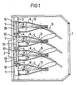
- Fig. 1 shows schematically a tool in the form of a plough where the invention is utilized
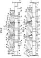
- Fig. 2 shows a detached part of the tool that is the invention, with a certain distance between the soil working tools
- Fig. 3 shows the invention with another distance between the tools.
- the tool is shown schematically in Fig. 1 in the form of a frame 1 at which means 2 for fitting the plough to the tool coupling of the traction vehicle-tractor-is arranged.
- a beam 3 is attached to the frame sides, on one hand, and, on the other hand, by means of braces 4.
- the working tools, in this case plough bodies 5, are articulatedly attached to sleeves 7 movable along the beam 3 via plough ridges 6 with double arms.
- the plough bodies 5 can be adjusted by means of arms 8 and stone release means 9 and be kept on the right level during work.
- the tool described here is known as such and is for instance taught in Swedish Patent 8402338-1.
- a bearing 10 in the form of for instance two upright parallel ears is disposed on the upper side of the respective sleeve 7.
- a slewing bracket 11 is pivotably mounted in each bearing 10.
- the respective slewing bracket 11 has in addition to the bearing hole for the mounting of the arm in the bearing 10 two additional bearing holes 12 and 13, respectively, the distance between all the holes being equal-for natural reasons, as appears from below, the right slewing bracket as seen in Figs. 2 and 3 need not be provided with an outermost third bearing hole.
- a bracket 14 extends articulatedly from the central bearing hole 12 in the respective slewing bracket 11 to the bearing 10 of the sleeve 7 immediately nearby.
- Bracket 15 extends articulatedly from the outermost bearing hole 13 of the respective slewing bracket 11 to the central hole 12 of the adjacent slewing bracket 11.
- first bracket 14 and the second bracket 15 can be built together to one single bracket in theory, see Figs. 2 and 3, but for technical and functional reasons the brackets should be articulated with each other. These joints are shown at 16 in the Figures.
- a hydraulic piston-cylinder unit 17 is arranged diametrically to the bearings 10 relative to the beam 3.
- the cylinder is fitted to a bearing 18 of the left sleeve 7 as seen in Figs. 2 and 3 and the piston rod is extended by means of a rod 19 which is connected with its outermost end to a bearing 20 of the right sleeve 7, as seen in Figs. 2 and 3.
- a position of the sleeves 7 is shown in which these and consequently the plough bodies 5 are at a smaller distance from each other.
- the position is shown where the sleeves 7 and consequently the plough bodies 5 are at a greater distance from each other.
- the third sleeve must move the distance 2a from the first-mentioned sleeve and the fourth sleeve the distance 3a from the first-mentioned sleeve.
- the extension rod 19 of the piston rod is movably mounted in the intermediate sleeves 7 by means of for instance flanges 21 provided with holes.
- the piston is operated from the driver's cabin on the traction vehicle (not shown).
- bracket system can be formed in other ways within the scope of the invention, the desired effect being achieved, and there are several different possibilities for one skilled in the art.
- the embodiment described here as an example can be produced very simply and cheaply and at the same time it has a good reliability in function with a possibility to good measure tolerances.
- more than four sleeves 7 or equivalent means can be operated in the way described above depending on the form and appearance of the beam.
Landscapes
- Life Sciences & Earth Sciences (AREA)
- Engineering & Computer Science (AREA)
- Mechanical Engineering (AREA)
- Soil Sciences (AREA)
- Environmental Sciences (AREA)
- Zoology (AREA)
- Soil Working Implements (AREA)
- Lifting Devices For Agricultural Implements (AREA)
- Electrical Discharge Machining, Electrochemical Machining, And Combined Machining (AREA)
- Constituent Portions Of Griding Lathes, Driving, Sensing And Control (AREA)
- Grinding And Polishing Of Tertiary Curved Surfaces And Surfaces With Complex Shapes (AREA)
- Forklifts And Lifting Vehicles (AREA)
- Earth Drilling (AREA)
- Harvester Elements (AREA)
- Heterocyclic Carbon Compounds Containing A Hetero Ring Having Oxygen Or Sulfur (AREA)
- Agricultural Machines (AREA)
Priority Applications (1)
| Application Number | Priority Date | Filing Date | Title |
|---|---|---|---|
| AT87850080T ATE60188T1 (de) | 1986-03-21 | 1987-03-12 | Vorrichtung zum einstellen der abstaende zwischen bodenbearbeitungsgeraeten. |
Applications Claiming Priority (2)
| Application Number | Priority Date | Filing Date | Title |
|---|---|---|---|
| SE8601335 | 1986-03-21 | ||
| SE8601335A SE458006B (sv) | 1986-03-21 | 1986-03-21 | Anordning foer instaellning av avstaandet mellan jordbearbetande redskap |
Publications (2)
| Publication Number | Publication Date |
|---|---|
| EP0238465A1 EP0238465A1 (en) | 1987-09-23 |
| EP0238465B1 true EP0238465B1 (en) | 1991-01-23 |
Family
ID=20363934
Family Applications (1)
| Application Number | Title | Priority Date | Filing Date |
|---|---|---|---|
| EP87850080A Expired EP0238465B1 (en) | 1986-03-21 | 1987-03-12 | A device for adjusting the distance between soil working tools |
Country Status (15)
| Country | Link |
|---|---|
| US (1) | US4828043A (sv) |
| EP (1) | EP0238465B1 (sv) |
| JP (1) | JPS62220101A (sv) |
| CN (1) | CN1006441B (sv) |
| AT (1) | ATE60188T1 (sv) |
| AU (1) | AU588092B2 (sv) |
| CA (1) | CA1271079A (sv) |
| DE (1) | DE3767520D1 (sv) |
| DK (1) | DK139687A (sv) |
| ES (1) | ES2019970B3 (sv) |
| FI (1) | FI871220A (sv) |
| GR (1) | GR3001554T3 (sv) |
| NO (1) | NO165821C (sv) |
| SE (1) | SE458006B (sv) |
| SU (1) | SU1553004A3 (sv) |
Families Citing this family (13)
| Publication number | Priority date | Publication date | Assignee | Title |
|---|---|---|---|---|
| DE3917438C1 (sv) * | 1989-05-29 | 1990-10-18 | Karl Becker Gmbh & Co Kg Maschinenfabrik, 3525 Oberweser, De | |
| US5063728A (en) * | 1990-12-03 | 1991-11-12 | J. I. Case Company | Apparatus for mounting a row unit for lateral movement |
| FR2692101A1 (fr) * | 1992-06-12 | 1993-12-17 | Lignones Hubert | Appareil de travail pour cultures en lignes. |
| US5361567A (en) * | 1993-01-26 | 1994-11-08 | Case Corporation | Multi-piece tool bar assembly for an agricultural implement |
| US5394945A (en) * | 1993-04-16 | 1995-03-07 | Desmarais; Robert | Precision weeding machine for row crops |
| FI20030990A (sv) * | 2003-07-01 | 2005-01-02 | Metalliasennus Huuhka Oy | Jord bearbetnings anordning |
| DE102004028642A1 (de) * | 2004-06-15 | 2006-01-05 | John Deere Fabriek Horst B.V. | Land-, forst- oder gartenwirtschaftliche Maschine |
| FR2988261A1 (fr) * | 2012-03-21 | 2013-09-27 | Earl Zimmerman | Dispositif de travail du sol en preparation des semis. |
| DE102015108505A1 (de) * | 2015-05-29 | 2016-12-01 | Lemken Gmbh & Co. Kg | Aufsattelpflug |
| EP3406125B1 (en) * | 2017-05-26 | 2020-11-04 | Deere & Company | Autonomous or remote controlled vehicle platform for planting |
| US10172274B2 (en) | 2017-05-26 | 2019-01-08 | Deere & Company | Autonomous or remote-controlled vehicle platform for spraying |
| US10542666B2 (en) | 2017-05-26 | 2020-01-28 | Deere & Company | Autonomous or remote-controlled vehicle platform for planting |
| US10820585B2 (en) * | 2017-09-13 | 2020-11-03 | Deere & Company | Sprayer systems with retractable drop apparatuses |
Family Cites Families (8)
| Publication number | Priority date | Publication date | Assignee | Title |
|---|---|---|---|---|
| US770372A (en) * | 1904-09-20 | Frank a | ||
| US1189982A (en) * | 1915-07-07 | 1916-07-04 | Mckay Disc Plow Co | Disk plow. |
| DE817828C (de) * | 1948-01-22 | 1951-10-22 | Chemische Werte A G Ges | Vorrichtung zur Halterung von Bodenbearbeitungsgeraeten |
| FR1006494A (fr) * | 1948-01-22 | 1952-04-23 | Bungartz & Co | Dispositif pour la fixation et le réglage d'outils multiples pour le travail de la terre |
| DE935583C (de) * | 1953-07-15 | 1955-11-24 | Lemken Kg Pflugfab | Vorrichtung zur AEnderung der Gesamtarbeitsbreite eines Scheibenpfluges mit einer Mehrzahl von Pflugscheiben |
| FR1353116A (fr) * | 1963-02-12 | 1964-02-21 | Lely Nv C Van Der | Dispositif destiné à la culture en rangées de végétaux |
| FR2254176A5 (en) * | 1973-11-12 | 1975-07-04 | Bersoult Roland | Extensible spray bar for agricultural use - has nozzles on lazy-tongs system extending in two planes |
| GB1574517A (en) * | 1976-11-30 | 1980-09-10 | Sugano Corp | Moulbord plow |
-
1986
- 1986-03-21 SE SE8601335A patent/SE458006B/sv not_active IP Right Cessation
-
1987
- 1987-02-17 CA CA000529869A patent/CA1271079A/en not_active Expired
- 1987-02-18 JP JP62036876A patent/JPS62220101A/ja active Pending
- 1987-03-09 SU SU874202114A patent/SU1553004A3/ru active
- 1987-03-11 CN CN87101941.8A patent/CN1006441B/zh not_active Expired
- 1987-03-12 AT AT87850080T patent/ATE60188T1/de active
- 1987-03-12 EP EP87850080A patent/EP0238465B1/en not_active Expired
- 1987-03-12 DE DE8787850080T patent/DE3767520D1/de not_active Expired - Lifetime
- 1987-03-12 ES ES87850080T patent/ES2019970B3/es not_active Expired - Lifetime
- 1987-03-18 DK DK139687A patent/DK139687A/da not_active Application Discontinuation
- 1987-03-19 US US07/028,194 patent/US4828043A/en not_active Expired - Fee Related
- 1987-03-19 FI FI871220A patent/FI871220A/fi not_active IP Right Cessation
- 1987-03-20 NO NO871172A patent/NO165821C/no unknown
- 1987-03-20 AU AU70436/87A patent/AU588092B2/en not_active Ceased
-
1991
- 1991-03-05 GR GR91400267T patent/GR3001554T3/el unknown
Also Published As
| Publication number | Publication date |
|---|---|
| CA1271079A (en) | 1990-07-03 |
| AU7043687A (en) | 1987-09-24 |
| NO165821B (no) | 1991-01-07 |
| CN87101941A (zh) | 1987-10-07 |
| SE458006B (sv) | 1989-02-20 |
| US4828043A (en) | 1989-05-09 |
| JPS62220101A (ja) | 1987-09-28 |
| SE8601335L (sv) | 1987-09-22 |
| NO871172D0 (no) | 1987-03-20 |
| SE8601335D0 (sv) | 1986-03-21 |
| AU588092B2 (en) | 1989-09-07 |
| SU1553004A3 (ru) | 1990-03-23 |
| ES2019970B3 (es) | 1991-07-16 |
| FI871220A (fi) | 1987-09-22 |
| NO165821C (no) | 1991-04-17 |
| CN1006441B (zh) | 1990-01-17 |
| GR3001554T3 (en) | 1992-11-23 |
| DE3767520D1 (de) | 1991-02-28 |
| DK139687D0 (da) | 1987-03-18 |
| DK139687A (da) | 1987-09-22 |
| ATE60188T1 (de) | 1991-02-15 |
| NO871172L (no) | 1987-09-22 |
| EP0238465A1 (en) | 1987-09-23 |
| FI871220A0 (fi) | 1987-03-19 |
Similar Documents
| Publication | Publication Date | Title |
|---|---|---|
| CA2339017C (en) | Hitch assembly for a work machine | |
| EP0238465B1 (en) | A device for adjusting the distance between soil working tools | |
| US4125271A (en) | Tool suspension | |
| EP1593294B1 (de) | Aufhängungsvorrichtung für ein Mähwerk | |
| US4004640A (en) | Hanger mechanism and sail engaging tool attached to tool bar thereby | |
| US5661917A (en) | Civil engineering works machine in which the working tool is mounted at the end of an articulated arm | |
| CA1197720A (en) | Plow | |
| US3481408A (en) | Multiple section earthworking implement | |
| US3708017A (en) | Arrangement for mounting agricultural implements on a tractor with rocking side transmissions | |
| US4660652A (en) | Hydraulic trip mechanism | |
| US4487267A (en) | Agricultural apparatus with tool supported thereon and wheel adjustment structure therefor | |
| GB2144312A (en) | Mounted or semi-mounted rotary plough | |
| SK280145B6 (sk) | Nesený otočný pluh s premenným nastavením pracovne | |
| ITMI970416A1 (it) | Aratro con un dispositivo per regolare l'ampiezza dei solchi anteriori la linea di azione trattore-aratro e la larghezza di aratura per la | |
| CA1072346A (en) | Unit comprising a tractor and an agricultural implement with attachments | |
| US4411323A (en) | Grading machine | |
| US5964167A (en) | Variable width field implement | |
| SU1650021A1 (ru) | Полунавесна рама-сцепка | |
| JPS6159682B2 (sv) | ||
| US3589447A (en) | Control system for dozer | |
| SU1759258A1 (ru) | Дисково-щелерезное орудие дл горных склонов | |
| GB2240245A (en) | A semi-trailer rotating plough | |
| SU468605A1 (ru) | Механизм навески сельскохоз йственных орудий на трактор | |
| CN2130321Y (zh) | 自动移重调角悬挂式松耙机 | |
| JPH0432895Y2 (sv) |
Legal Events
| Date | Code | Title | Description |
|---|---|---|---|
| PUAI | Public reference made under article 153(3) epc to a published international application that has entered the european phase |
Free format text: ORIGINAL CODE: 0009012 |
|
| AK | Designated contracting states |
Kind code of ref document: A1 Designated state(s): AT BE CH DE ES FR GB GR IT LI NL SE |
|
| 17P | Request for examination filed |
Effective date: 19871204 |
|
| 17Q | First examination report despatched |
Effective date: 19881108 |
|
| GRAA | (expected) grant |
Free format text: ORIGINAL CODE: 0009210 |
|
| AK | Designated contracting states |
Kind code of ref document: B1 Designated state(s): AT BE CH DE ES FR GB GR IT LI NL SE |
|
| PG25 | Lapsed in a contracting state [announced via postgrant information from national office to epo] |
Ref country code: SE Effective date: 19910123 Ref country code: GR Free format text: LAPSE BECAUSE OF FAILURE TO SUBMIT A TRANSLATION OF THE DESCRIPTION OR TO PAY THE FEE WITHIN THE PRESCRIBED TIME-LIMIT Effective date: 19910123 |
|
| REF | Corresponds to: |
Ref document number: 60188 Country of ref document: AT Date of ref document: 19910215 Kind code of ref document: T |
|
| REF | Corresponds to: |
Ref document number: 3767520 Country of ref document: DE Date of ref document: 19910228 |
|
| ITF | It: translation for a ep patent filed |
Owner name: STUDIO TORTA SOCIETA' SEMPLICE |
|
| PG25 | Lapsed in a contracting state [announced via postgrant information from national office to epo] |
Ref country code: AT Effective date: 19910312 |
|
| PG25 | Lapsed in a contracting state [announced via postgrant information from national office to epo] |
Ref country code: ES Free format text: LAPSE BECAUSE OF NON-PAYMENT OF DUE FEES Effective date: 19910313 |
|
| ET | Fr: translation filed | ||
| PG25 | Lapsed in a contracting state [announced via postgrant information from national office to epo] |
Ref country code: LI Effective date: 19910331 Ref country code: CH Effective date: 19910331 Ref country code: BE Effective date: 19910331 |
|
| PG25 | Lapsed in a contracting state [announced via postgrant information from national office to epo] |
Ref country code: GB Effective date: 19910423 |
|
| BERE | Be: lapsed |
Owner name: KARLSSON RUNE Effective date: 19910331 |
|
| PG25 | Lapsed in a contracting state [announced via postgrant information from national office to epo] |
Ref country code: NL Effective date: 19911001 |
|
| NLV4 | Nl: lapsed or anulled due to non-payment of the annual fee | ||
| PLBE | No opposition filed within time limit |
Free format text: ORIGINAL CODE: 0009261 |
|
| STAA | Information on the status of an ep patent application or granted ep patent |
Free format text: STATUS: NO OPPOSITION FILED WITHIN TIME LIMIT |
|
| REG | Reference to a national code |
Ref country code: CH Ref legal event code: PL |
|
| GBPC | Gb: european patent ceased through non-payment of renewal fee | ||
| 26N | No opposition filed | ||
| REG | Reference to a national code |
Ref country code: GR Ref legal event code: FG4A Free format text: 3001554 |
|
| PGFP | Annual fee paid to national office [announced via postgrant information from national office to epo] |
Ref country code: FR Payment date: 19940318 Year of fee payment: 8 |
|
| PGFP | Annual fee paid to national office [announced via postgrant information from national office to epo] |
Ref country code: DE Payment date: 19940530 Year of fee payment: 8 |
|
| REG | Reference to a national code |
Ref country code: GR Ref legal event code: MM2A Free format text: 3001554 |
|
| PG25 | Lapsed in a contracting state [announced via postgrant information from national office to epo] |
Ref country code: FR Free format text: LAPSE BECAUSE OF NON-PAYMENT OF DUE FEES Effective date: 19951130 |
|
| PG25 | Lapsed in a contracting state [announced via postgrant information from national office to epo] |
Ref country code: DE Effective date: 19951201 |
|
| REG | Reference to a national code |
Ref country code: FR Ref legal event code: ST |
|
| REG | Reference to a national code |
Ref country code: ES Ref legal event code: FD2A Effective date: 19990201 |
|
| PG25 | Lapsed in a contracting state [announced via postgrant information from national office to epo] |
Ref country code: IT Free format text: LAPSE BECAUSE OF NON-PAYMENT OF DUE FEES Effective date: 20050312 |