EP0238084A2 - Vorrichtung zum Anbringen einer monomolekularen Schicht - Google Patents
Vorrichtung zum Anbringen einer monomolekularen Schicht Download PDFInfo
- Publication number
- EP0238084A2 EP0238084A2 EP87104036A EP87104036A EP0238084A2 EP 0238084 A2 EP0238084 A2 EP 0238084A2 EP 87104036 A EP87104036 A EP 87104036A EP 87104036 A EP87104036 A EP 87104036A EP 0238084 A2 EP0238084 A2 EP 0238084A2
- Authority
- EP
- European Patent Office
- Prior art keywords
- mono
- molecular layer
- substrate
- container
- liquid surface
- Prior art date
- Legal status (The legal status is an assumption and is not a legal conclusion. Google has not performed a legal analysis and makes no representation as to the accuracy of the status listed.)
- Granted
Links
Images


Classifications
-
- B—PERFORMING OPERATIONS; TRANSPORTING
- B05—SPRAYING OR ATOMISING IN GENERAL; APPLYING FLUENT MATERIALS TO SURFACES, IN GENERAL
- B05C—APPARATUS FOR APPLYING FLUENT MATERIALS TO SURFACES, IN GENERAL
- B05C3/00—Apparatus in which the work is brought into contact with a bulk quantity of liquid or other fluent material
- B05C3/02—Apparatus in which the work is brought into contact with a bulk quantity of liquid or other fluent material the work being immersed in the liquid or other fluent material
- B05C3/09—Apparatus in which the work is brought into contact with a bulk quantity of liquid or other fluent material the work being immersed in the liquid or other fluent material for treating separate articles
- B05C3/109—Passing liquids or other fluent materials into or through chambers containing stationary articles
-
- B—PERFORMING OPERATIONS; TRANSPORTING
- B05—SPRAYING OR ATOMISING IN GENERAL; APPLYING FLUENT MATERIALS TO SURFACES, IN GENERAL
- B05D—PROCESSES FOR APPLYING FLUENT MATERIALS TO SURFACES, IN GENERAL
- B05D1/00—Processes for applying liquids or other fluent materials
- B05D1/18—Processes for applying liquids or other fluent materials performed by dipping
- B05D1/20—Processes for applying liquids or other fluent materials performed by dipping substances to be applied floating on a fluid
- B05D1/202—Langmuir Blodgett films (LB films)
- B05D1/206—LB troughs
-
- B—PERFORMING OPERATIONS; TRANSPORTING
- B82—NANOTECHNOLOGY
- B82Y—SPECIFIC USES OR APPLICATIONS OF NANOSTRUCTURES; MEASUREMENT OR ANALYSIS OF NANOSTRUCTURES; MANUFACTURE OR TREATMENT OF NANOSTRUCTURES
- B82Y30/00—Nanotechnology for materials or surface science, e.g. nanocomposites
-
- B—PERFORMING OPERATIONS; TRANSPORTING
- B82—NANOTECHNOLOGY
- B82Y—SPECIFIC USES OR APPLICATIONS OF NANOSTRUCTURES; MEASUREMENT OR ANALYSIS OF NANOSTRUCTURES; MANUFACTURE OR TREATMENT OF NANOSTRUCTURES
- B82Y40/00—Manufacture or treatment of nanostructures
-
- G—PHYSICS
- G03—PHOTOGRAPHY; CINEMATOGRAPHY; ANALOGOUS TECHNIQUES USING WAVES OTHER THAN OPTICAL WAVES; ELECTROGRAPHY; HOLOGRAPHY
- G03F—PHOTOMECHANICAL PRODUCTION OF TEXTURED OR PATTERNED SURFACES, e.g. FOR PRINTING, FOR PROCESSING OF SEMICONDUCTOR DEVICES; MATERIALS THEREFOR; ORIGINALS THEREFOR; APPARATUS SPECIALLY ADAPTED THEREFOR
- G03F7/00—Photomechanical, e.g. photolithographic, production of textured or patterned surfaces, e.g. printing surfaces; Materials therefor, e.g. comprising photoresists; Apparatus specially adapted therefor
- G03F7/16—Coating processes; Apparatus therefor
- G03F7/165—Monolayers, e.g. Langmuir-Blodgett
Definitions
- the present invention generally relates to apparatuses for depositing a mono-molecular layer, and more particularly to an apparatus for depositing a mono-molecular layer on a surface of a substrate by immersion of the substrate into a liquid having the mono-molecular layer at a liquid surface.
- a resist coater is used when depositing a resist layer on a wafer.
- the resist coater rotates the wafer and drops a predetermined quantity of the resist onto the rotating wafer so as to deposit the resist layer on the wafer by use of centrifugal force.
- a method of forming a mono-molecular layer (or film) at a liquid surface and depositing the mono-molecular layer on the substrate by immersing the substrate into the liquid Such a mono-molecular layer is often referred to as a Langmuir Blodgett layer (or film).
- the mono-molecular layer is deposited on the substrate surface either on the first down pass or the first up pass of the substrate through the air/liquid interface.
- the conventional apparatus for depositing a resist mono-molecular layer on the substrate comprises an elevator mechanism for raising and lowering the substrate with respect to purified water having the resist mono-molecular layer at the water surface.
- the substrate is immersed into the water and then raised with the substrate surfaces approximately perpendicular to the water surface.
- the substrate is lowered to the water surface with the substrate surface approximately parallel to the water surface, without substantially immersing the substrate into the water.
- the mono-molecular layer at the water surface is extremely sensitive to vibration (dynamic force) and will be damaged when subjected to the vibration.
- the substrate itself vibrates since it is raised and lowered by the elevator mechanism, and such vibration of the substrate is inevitable.
- the vibration of the substrate acts on the mono-molecular layer as the substrate makes contact with the water surface, and there is a problem in that the mono-molecular layer is easily disturbed and damaged.
- the elevator mechanism is located above the mono-molecular layer, dust particles and the like generated from the elevator mechanism fall on the mono-molecular layer and easily disturb and damage the mono-molecular layer.
- the conventional apparatus collects the molecules in one direction. But in order to prevent the molecules from being distributed unevenly, that is, to prevent holes and molecule overlap, the molecules must be collected in the one direction with extreme care. Otherwise, the mono-molecular layer at the water surface becomes non-uniform, and it is impossible to deposit a uniform mono-molecular layer on the substrate surface from such a non-uniform mono-molecular layer.
- the conventional apparatus suffers disadvantages in that the mono-molecular layer cannot be deposited on the substrate surface with a high reliability.
- Another and more specific object of the present invention is to provide an apparatus which comprises first and second containers which contain a liquid and are connected via a connecting passage, and a pressure applying means for applying pressure on the liquid in the second container.
- a mono-molecular layer is formed at the liquid surface of the liquid in the first container, and the mono-molecular layer is deposited on a substrate surface by controlling the pressure applying means so that the liquid surface of the first container rises and falls with respect to the substrate which is stationary.
- the substrate itself will not vibrate because it is stationary, and the liquid surface of the first container will not be disturbed as the liquid surface level changes because the liquid surface of the first container is virtually unaffected by the disturbance in the liquid surface of the second container.
- Still another object of the present invention is to provide an apparatus which comprises first and second containers which contain a liquid and are connected via a connecting passage, and a pressure applying means for applying pressure on the liquid in the second container, where the liquid surface area of the first container is greater than that of the second container.
- a mono-molecular layer is formed at the liquid surface of the liquid in the first container, and the mono-molecular layer is deposited on a substrate by controlling the pressure applying means so that the liquid surface of the first container rises and falls with respect to the substrate which is supported by spring means.
- the substrate itself will not vibrate because it is essentially stationary and is not moved by an elevator mechanism, and the liquid surface of the first container will not be disturbed as the liquid surface level changes because the liquid surface of the first container is virtually unaffected by the disturbance in the liquid surface of the second container especially due to the large liquid surface area of the first container.
- the spring means prevents excessive immersion of the substrate into the water when the liquid surface makes contact with the substrate surface which is approximately parallel to the liquid surface. As a result, it is possible to prevent the mono-molecular layer from becoming damaged at the liquid surface of the first container. In addition, it is possible to prevent dust particles and the like from falling on the mono-molecular layer damaging the mono-molecular layer because no elevator mechanism is required to move the substrate.
- a further object of the present invention is to provide an apparatus of the types described before in which the liquid surface of the first container is raised and lowered instead of moving the substrate, and which is provided with a flexible loop barrier at the liquid surface of the first container for efficiently collecting the molecules to form the mono-molecular layer at the liquid surface by reducing the size of the flexible loop barrier.
- the apparatus of the present invention it is possible to form a uniform mono-molecular layer at the liquid surface of the first container, and the reliability with which a uniform mono-molecular layer is deposited on the substrate surface is improved compared to the conventional apparatus.
- the size of the flexible loop barrier can be reduced successively with each deposition.
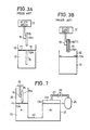
- FIGS.1A and 1B show one example of the conventional apparatus which is designed to deposit a resist mono-molecular layer on one substrate surface by moving a substrate with the substrate surface kept approximately parallel to the liquid surface.
- a uniform resist mono-molecular layer 11 consisting of resist molecules 14 is formed at a liquid surface 13a of a liquid 13 contained in a container 12.
- purified water is used as the liquid 13.
- FIGS.2A and 2B are a top view and a side view in cross section showing a conventional barrier for forming the resist mono-molecular layer 11 at the liquid surface 13a.
- FIGS.2A and 2B those parts which are the same as those corresponding parts in FIGS.1A and 1B are designated by the same reference numerals, and description thereof will be omitted.
- a barrier 19 moves in a direction A so as to collect the resist molecules 14 and form a uniform resist mono-molecular layer 11 at the liquid surface 13a.
- a substrate (wafer, for example) 15 is secured on a chuck 16 with a surface 15a thereof facing down to confront the resist mono-molecular layer 11.
- the chuck 16 is connected to an elevator mechanism 17 which is located above the container 12 and moves the substrate 15 up and down.
- a resist mono-molecular layer 18 (11) is deposited on the surface 15a of the substrate 15 when the elevator mechanism 17 lowers the substrate 15 so that the surface 15a makes contact with the resist mono-molecular layer 11 at the liquid surface 13a, and the substrate 15 is thereafter raised as shown in FIG.1B.
- FIGS.1A and 1B and FIGS.3A and 3B which will be described later, the illustration of the barrier 19 shown in FIGS.2A and 2B is omitted for convenience' sake.
- the resist mono-molecular layer 11 is extremely sensitive to vibration (dynamic force) and will be easily damaged by vibration.
- the elevator mechanism 17 must lower the substrate 15 at an extremely slow speed so as not to disturb the liquid surface 13a upon contact therewith. But in actual practice, it is difficult to prevent such a disturbance at the liquid surface 13a.
- the vibration of the elevator mechanism 17 is inevitably transmitted to the substrate 15 and the vibration of the substrate 15 itself easily damages the resist mono-molecular layer 11.
- the elevator mechanism 17 is located above the container 12, dust particles and the like generated from the elevator mechanism 17 fall on the resist mono-molecular layer 11 and easily damage the resist mono-molecular layer 11.
- FIGS.3A and 3B show another example of the conventional apparatus which is designed to deposit a resist mono-molecular layer on substrate surfaces by moving a substrate with the substrate surface kept approximately perpendicular to the liquid surface.
- FIGS.3A and 3B those parts which are the same as those corresponding parts in FIGS.1A and 1B are designated by the same reference numerals, and description thereof will be omitted.
- This apparatus shown in FIGS.3A and 3B differs from the apparatus shown in FIGS.1A and 1B only in that the substrate 15 is immersed into the liquid 13 and then taken out of the liquid 13 when depositing the resist mono-molecular layer 18 on the surfaces 15a of the substrate 15.
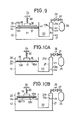
- FIGS.4A through 4C and FIGS.5A through 5C are diagrams for explaining the deposition of the resist mono-molecular layer 18 on the surface 15a.
- the substrate 15 having a suitably treated surface 15a is immersed into the liquid 13, breaking through the resist mono-molecular layer 11, one resist molecular layer is deposited on the surface 15a.
- the first resist molecular layer will adhere either on the first down pass or the first up pass of the substrate 15 through the air/liquid interface.
- a hydrophobic coating on the surface 15a will result in the deposition of a first resist molecular layer 181 on the first down pass as shown in FIG.4A since hydrophobic tails adhere to the hydrophobic surface, while no deposition takes place until the first up pass in the case of a hydrophillic coating on the surface 15a as may be seen from FIGS.5A and 5B.
- deposition occurs when the direction of the meniscus formed at boundary between the liquid surface and the substrate surface follows the substrate movement.
- an additional resist molecular layer (182, 183) is deposited every time the substrate 15 crosses the air/liquid interface as shown in FIGS.4B, 4C and 5C.
- the resist has such a characteristic that the hydrophobic tails of one resist mono-molecular layer adhere to the hydrophobic tails of an adjacent resist mono-molecular layer, and the hydrophillic heads of one resist mono-molecular layer adhere to the hydrophillic heads of an adjacent resist mono-molecular layer.
- the so-called Y-layer is formed.
- FIGS.6A through 6C show such a case.
- a hydrophobic coating on the surface 15a will result in the deposition of a first mono-molecular layer 18a on the first down pass as shown in FIG.6A since the hydrophobic tails adhere to the hydrophobic surface.
- no deposition takes place on the first up pass as shown in FIG.6B since the hydrophillic heads of the mono-molecular layer at the liquid surface do not adhere to the hydrophillic heads of the first mono-molecular layer 18a.
- a second mono-molecular layer 18b is deposited on the first mono-molecular layer 18a as shown in FIG.6C because the hydrophobic tails of the mono-molecular layer at the liquid surface adhere to the hydrophillic heads of the first mono-molecular layer 18a.
- the so-called X-layer is formed.
- the substrate surface 15a must by hydrophobic. Otherwise, since the hydrophillic heads of the mono-molecular layer 11 at the liquid surface 13a face the liquid 13 and the hydrophobic tails of the mono-molecular layer 11 face the air, no deposition would take place.
- the resist (or coating material) has the characteristic described before that forms the Y-layer, only one deposition of the mono-molecular layer is possible according to the arrangement shown in FIGS.1A and 1B. But in the case where the resist (or coating material) has the characteristic described before that forms the X-layer, successive deposition of the mono-molecular layer is possible even according to the arrangement shown in FIGS.1A and 1B.
- the present invention eliminates the problems of the conventional apparatuses described heretofore by keeping the substrate substantially stationary when depositing the mono-molecular layer on the substrate surface, and also provides an improvement in forming a uniform mono-molecular layer at the liquid surface.
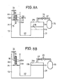
- FIG.7 shows the first embodiment of the apparatus according to the present invention.
- the apparatus comprises first and second containers 20 and 21 which are connected to each other via a connecting passage 22.
- the first and second containers 20 and 21 contain the liquid 13 which is purified water, for example.
- the liquid surface 13a of the first container 20 and a liquid surface 13b of the second container 21 both have a level H1 because the two containers 20 and 21 are communicated with each other via the connecting passage 22.
- the resist mono-molecular layer 11 is formed at the liquid surface 13a of the first container 20.
- the substrate 15 is secured on the chuck 16 with the surfaces 15a approximately perpendicular to the liquid surface 13a.
- the chuck 16 is fixed to a fixing part 24, and the substrate 15 is kept stationary. In the state shown in FIG.7, the substrate 15 is inside the first container 20 but is not in contact with the resist mono-molecular layer 11 nor the liquid 13.
- a pressure applying means 25 is constituted by a nitrogen gas cylinder, for example.
- the top of the second container 21 which is hermetically sealed is connected to a pipe arrangement 27 which connects to the pressure applying means 25.
- a valve 26 is provided at an intermediate part of the pipe arrangement 27.
- the surface 15a is hydrophillic (refer to FIGS.5A through 5C).
- the substrate 15 is secured on the chuck 16 and the resist mono-molecular layer 11 is formed on the liquid surface 13 by use of a barrier (not shown) such as that shown in FIGS.2A and 2B.
- pressurized nitrogen gas under a pressure of 8 kg/cm2 is fed into a space 21a in the second container 21 by gradually opening the valve 26, so as to apply pressure on the liquid surface 13b.
- pressurized nitrogen gas under a pressure of 8 kg/cm2 for example
- pressurized nitrogen gas under a pressure of 8 kg/cm2 for example
- the liquid surface 13b falls to a level H2, and the liquid surface 13a rises to a level H3 which exceeds the highest point on the substrate 15. In other words, the entire substrate 15 is immersed into the liquid 13 in the first container 20.
- FIG.8A shows an intermediate state where the liquid surface 13b has a level H4, the liquid surface 13a has a level H5, and the substrate 15 is halfway immersed into the liquid 13 in the first container 20. It will be assumed that the surfaces 15a of the substrate 15 have a hydrophillic coating, and thus, the deposition of the resist mono-molecular layer 18 gradually occurs during the first up pass of the substrate 15 through the air/liquid interface as shown in FIG.8A.
- the liquid surfaces 13a and 13b return to the original level H1 as shown in FIG.8B.
- the substrate 15 is completely out of the liquid 13, and the resist mono-molecular layer 18 is deposited on the surfaces 15a of the substrate 15.
- the operation of supplying the nitrogen gas into the space 21a and releasing the nitrogen gas in the space 21a to the atmosphere may be carried out again when an additional resist mono-molecular layer is to be formed on the first resist mono-molecular layer 18.
- a resist layer of a desired thickness may be deposited on the surfaces 15a by repeating such operations.
- the substrate 15 is prevented from vibrating because the substrate 15 is kept stationary, and consequently, there is no possibility of the resist mono-molecular layer 11 at the liquid surface 13a being disturbed by such vibration of the substrate 15.
- no elevator mechanism is required to raise and lower the substrate 15.
- the liquid surface 13a may be raised and lowered at a speed faster than the speed with which the substrate 15 is raised and lowered by the elevator mechanism of the conventional apparatus. Accordingly, the time required to deposit the resist mono-molecular layer 18 on the surfaces 15a is shortened compared to the time required in the conventional apparatus.
- the moving speed of the liquid surface 13a may be satisfactorily controlled by appropriately selecting a ratio of a horizontal cross sectional area (that is, the liquid surface area) A1 of the first container 20 and a horizontal cross sectional area (that is, the liquid surface area) A2 of the second container 21.
- FIG.9 shows the second embodiment of the apparatus according to the present invention.
- the cross sectional area A1 of the first container 20 is set to a value greater than the cross sectional area A2 of the second container 21.
- the substrate 15 is secured on the chuck 16 which is connected to the fixed part 24 via a spring means 30. Hence, the substrate 15 hangs from the fixed part 24 with the surface 15a approximately parallel to the liquid surface 13a.
- the surface 15a is hydrophobic.
- a ratio ⁇ l/ ⁇ m between a displacement ⁇ l of the liquid surface 13a and a displacement ⁇ m of the liquid surface 13b corresponds to the ratio A2/A1. Since A1>A2, the ratio ⁇ l/ ⁇ m is less than 1.0. The ratio ⁇ l/ ⁇ m is approximately 1/6 in the present embodiment. For this reason, the liquid surface 13a rises at an extremely slow speed without disturbing and damaging the resist mono-molecular layer 11 at the liquid surface 13a.
- the substrate 15 in the present embodiment is provided in a hanging manner by the spring means 30.
- the substrate 15 floats on the liquid surface 13a (or the resist mono-molecular layer 11) and rises with the liquid surface 13a, absorbing the shock upon contact. Hence, it is possible to prevent the substrate 15 from being excessively immersed into the liquid 13, and the shock upon contact is effectively absorbed so as to prevent disturbance and possible damage in the resist mono-molecular layer 11.
- the operation of supplying the nitrogen gas into the space 21a and releasing the nitrogen gas in the space 21a to the atmosphere may be repeated so as to deposit a resist layer of a desired thickness on the surface 15a.
- the vibration caused by the elevator mechanism is eliminated because the substrate 15 is kept substantially stationary and no elevator mechanism is required to raise and lower the substrate 15. Further, since no elevator mechanism is used, it is possible to prevent the resist mono-molecular layer 11 from being disturbed and damaged by the dust particles and the like generated from the elevator mechanism. Therefore, a uniform resist mono-molecular layer 18 can be deposited on the surface 15a with a high reliability.
- the shock upon contact of the surface 15a of the substrate 15 and the rising liquid surface 13a (that is, the resist mono-molecular layer 11) can be effectively reduced especially when the substrate 15 is arranged with the surface 15a arranged approximately parallel to the liquid surface 13a and the contact area is relatively large.
- the resist mono-molecular layer 11 is formed at the liquid surface 13a by use of the barrier such as that shown in FIGS.2A and 2B.
- the barrier 19 shown in FIGS.2A and 2B collect the resist molecules 14 in one direction, namely the direction A.
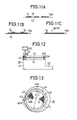
- the displacement of the barrier 19 and the resist layer portions or molecules are generally in the same direction A, and the barrier 19 must be moved with extreme care so as not to leave holes 31 in the resist mono-molecular layer 11 as shown in FIG.11A due to insufficient collection of the resist molecules nor generate resist molecular overlap as shown in FIG.11B due to over-collection of the resist molecules.
- the formation of the resist mono-molecular layer 11 at the liquid surface 13a is extremely difficult to control.
- FIG.12 shows a modification of the first and second embodiments.
- those parts which are the same as those corresponding parts in FIGS.7 and 9 are designated by the same reference numerals, and description thereof will be omitted.
- the illustration of the substrate 15 and the second container 21 is omitted for convenience' sake.
- a flexible loop barrier shown in FIG.13 constitutes an essential part of this modification.
- a flexible loop barrier 44 comprises a resilient belt-shaped member 40 which is bent in the form of a ring.
- the surface of the member 40 is made of teflon (registered trademark) so that the resist molecules 14 will not easily adhere on the member 40.
- One end 40a of the member 40 is fixed to a portion of the inner peripheral wall of the first container 20 by a fixing part 43, and another end 40b of the member 40 is wound around a vertical shaft 342 in a vicinity of the one end 40a.
- the size of the loop barrier 44 may be changed by rotating the vertical shaft 42 or by moving the vertical shaft 42 along the inner peripheral wall of the first container 20 by use of a driving means 50 shown in FIG.12.
- the member 40 is immersed into the liquid 13 as shown in FIG.12 so that approximately the lower half of the member 40 along the width thereof is in the liquid 13 and approximately the upper half of the member 40 along the width thereof is above the liquid surface 13a.
- the resist molecules 14 are distributed on the liquid surface 14 inside the loop barrier 44, and the vertical shaft 42 is rotated in a direction B by the driving means 50 while measuring the layer stress of the resist mono-molecular layer 11 by use of a measuring apparatus (not shown), so as to reduce the size of the loop barrier 44.
- the vertical shaft 42 is rotated in the direction B, the member 40 is taken up from the other end 40b, and a diameter d of the loop barrier 44 gradually decreases while maintaining the loop shape.
- the resist molecules 14 are collected towards the center of the loop barrier 44 and the resist mono-molecular layer 11 is formed at the liquid surface 13a inside the loop barrier 44.
- a radius r of the loop barrier 44 is reduced by a length ⁇ r and the size of the loop barrier 44 is reduced.
- the diameter d of the loop barrier 44 changes extremely slowly as the vertical shaft 42 is rotated while measuring the layer stress of the resist-mono-molecular layer 11, and the distributed resist molecules 14 are uniformly collected towards the center of the loop barrier 44 under extremely fine control. Therefore, a uniform resist mono-molecular layer 11 shown in FIG.11C can be formed at the liquid surface 13a by finely controlling the diameter d, without generating holes or molecule overlap shown in FIGS.11A and 11B.
- the diameter d and shape of the loop barrier 44 returns back to the original diameter and shape due to the flexibility thereof when the taking-up force acting on the vertical shaft 42 is released.
- the diameter d of the loop barrier 44 may be reduced appropriately when level of the liquid surface 13a changes and the substrate 15 is relatively immersed into and taken out of the liquid 13, depending on the deposition of the resist mono-molecular layer 18 on the surfaces 15a of the substrate 15, in the case where the substrate 15 is arranged vertically so that the surfaces 15a are approximately perpendicular to the liquid surface 13a.
- the deposition of the resist mono-molecular layer 18 on the surfaces 15a can be carried out repeatedly to a predetermined layer thickness by successively reducing the diameter d without the need to add resist molecules 14 with every deposition, provided that the cross sectional area A1 of the first container 20 and the diameter d are sufficiently large.
- the repetitive deposition of the resist mono-molecular layer 18 on the surface 15a of the substrate 15 which is arranged horizontally so that the surface 15a is approximately parallel to the liquid surface 13a may be carried out similarly by successively and appropriately reducing the diameter d of the loop barrier 44 in FIG.12.
- a resist mono-molecular layer is deposited on a substrate surface.
- the mono-molecular layer deposited on the substrate surface by the apparatus of the present invention is not limited to the resist mono-molecular layer, and other inorganic and organic mono-molecular layers may be deposited in the same manner.
- an organic mono-molecular layer such as a vinyl stearate mono-molecular layer and a diacetylene derivative mono-molecular layer may be deposited on the substrate surface by the apparatus of the present invention. It is also possible to deposit a semiconducting mono-molecular layer and an insulating mono-molecular layer by the apparatus of the present invention.
- the liquid used to form the mono-molecular layer at the liquid surface thereof is of course not limited to purified water, and any liquid may be used as long as the molecules constituting the mono-molecular layer which is to be deposited are insoluble to the liquid and the mono-molecular layer can be formed satisfactorily at the liquid surface.
Landscapes
- Engineering & Computer Science (AREA)
- Chemical & Material Sciences (AREA)
- Nanotechnology (AREA)
- Physics & Mathematics (AREA)
- General Physics & Mathematics (AREA)
- Condensed Matter Physics & Semiconductors (AREA)
- Crystallography & Structural Chemistry (AREA)
- Composite Materials (AREA)
- Materials Engineering (AREA)
- Manufacturing & Machinery (AREA)
- Coating Apparatus (AREA)
- Application Of Or Painting With Fluid Materials (AREA)
Applications Claiming Priority (6)
| Application Number | Priority Date | Filing Date | Title |
|---|---|---|---|
| JP61274/86 | 1986-03-19 | ||
| JP61061274A JPS62217615A (ja) | 1986-03-19 | 1986-03-19 | 半導体素子の製造方法 |
| JP61090348A JP2545363B2 (ja) | 1986-04-18 | 1986-04-18 | 基板上へのレジスト層形成方法 |
| JP90348/86 | 1986-04-18 | ||
| JP142539/86 | 1986-06-18 | ||
| JP14253986A JPS62299030A (ja) | 1986-06-18 | 1986-06-18 | 基板上へのレジスト層形成装置 |
Publications (3)
| Publication Number | Publication Date |
|---|---|
| EP0238084A2 true EP0238084A2 (de) | 1987-09-23 |
| EP0238084A3 EP0238084A3 (en) | 1988-01-27 |
| EP0238084B1 EP0238084B1 (de) | 1990-09-26 |
Family
ID=27297448
Family Applications (1)
| Application Number | Title | Priority Date | Filing Date |
|---|---|---|---|
| EP87104036A Expired EP0238084B1 (de) | 1986-03-19 | 1987-03-19 | Vorrichtung zum Anbringen einer monomolekularen Schicht |
Country Status (3)
| Country | Link |
|---|---|
| US (1) | US4779562A (de) |
| EP (1) | EP0238084B1 (de) |
| DE (1) | DE3765144D1 (de) |
Families Citing this family (12)
| Publication number | Priority date | Publication date | Assignee | Title |
|---|---|---|---|---|
| US5021268A (en) * | 1990-01-17 | 1991-06-04 | The United States Of America As Represented By The Secretary Of The Air Force | Method of making asymmetric Langmuir-Blodgett films |
| US5232503A (en) * | 1991-10-07 | 1993-08-03 | San Jose Technology | Apparatus for evaporatively coating objects with a predetermined thickness profile |
| JP2828386B2 (ja) | 1993-08-31 | 1998-11-25 | 科学技術振興事業団 | 微粒子薄膜の製造方法 |
| US6068878A (en) * | 1998-09-03 | 2000-05-30 | Micron Technology, Inc. | Methods of forming layers of particulates on substrates |
| DK173587B1 (da) * | 1999-10-08 | 2001-04-02 | Gram Equipment As | Fremgangsmåde samt apparat til coating af et produkt |
| WO2001068834A1 (en) * | 2000-03-16 | 2001-09-20 | Matsushita Electric Industrial Co., Ltd. | Nucleotide detector, process for producing the same and process for forming fine particle membrane |
| US20050045097A1 (en) * | 2003-08-28 | 2005-03-03 | 3M Innovative Properties Company | Dip coating apparatus |
| CN100402161C (zh) * | 2005-12-23 | 2008-07-16 | 山东轻工业学院 | 在陶瓷釉面砖上制备纳米薄膜的方法及纳米薄膜镀膜机 |
| WO2009119155A1 (ja) * | 2008-03-24 | 2009-10-01 | 日本碍子株式会社 | 塗布膜形成方法及び塗布膜形成装置 |
| TWI425648B (zh) * | 2009-12-31 | 2014-02-01 | Film making system and film making method | |
| CN105032718B (zh) * | 2015-06-24 | 2017-08-22 | 惠州易晖光电材料股份有限公司 | 一种连续性水平浸渍镀膜系统及方法 |
| US11513071B2 (en) * | 2019-10-15 | 2022-11-29 | 2Witech Solutions Llc | Sensing device for detecting analyte containing non-metallic element, and method thereof |
Family Cites Families (7)
| Publication number | Priority date | Publication date | Assignee | Title |
|---|---|---|---|---|
| US618672A (en) * | 1899-01-31 | Charles henry | ||
| GB405761A (en) * | 1932-10-27 | 1934-02-15 | George Mackenzie Brown | Improvements in or relating to apparatus for surfacing sheet material with pigments,varnishes, lacquers or the like |
| US2255436A (en) * | 1939-09-19 | 1941-09-09 | Anaconda Wire & Cable Co | Coating apparatus and method of operation |
| US3557749A (en) * | 1969-03-12 | 1971-01-26 | George Farago | Immersion apparatus |
| US4204498A (en) * | 1978-05-31 | 1980-05-27 | Emil Ivancic | Apparatus for applying coating liquid to articles |
| FR2541936B1 (fr) * | 1983-03-04 | 1985-10-04 | Commissariat Energie Atomique | Procede et dispositif pour la realisation de couches monomoleculaires alternees |
| GB8417959D0 (en) * | 1984-07-14 | 1984-08-15 | Nima Technology Ltd | Barrier system |
-
1987
- 1987-03-12 US US07/025,253 patent/US4779562A/en not_active Expired - Fee Related
- 1987-03-19 EP EP87104036A patent/EP0238084B1/de not_active Expired
- 1987-03-19 DE DE8787104036T patent/DE3765144D1/de not_active Expired - Lifetime
Also Published As
| Publication number | Publication date |
|---|---|
| US4779562A (en) | 1988-10-25 |
| EP0238084A3 (en) | 1988-01-27 |
| EP0238084B1 (de) | 1990-09-26 |
| DE3765144D1 (de) | 1990-10-31 |
Similar Documents
| Publication | Publication Date | Title |
|---|---|---|
| US4779562A (en) | Apparatus for depositing mono-molecular layer | |
| KR100991723B1 (ko) | 고상파우더 연속 증착 롤투롤 장치 | |
| EP1043123A2 (de) | Pufferarbeitsstelle in einer chemisch-mechanischen Poliervorrichtung | |
| CN101501833A (zh) | 支撑基片的装置 | |
| US5455062A (en) | Capillary device for lacquering or coating plates or disks | |
| US20020072251A1 (en) | Method for manufacturing semiconductor device | |
| JPH09186219A (ja) | ウェーハホルダ | |
| US20010027613A1 (en) | Drying apparatus and method | |
| JPS62252396A (ja) | 単結晶引き上げ装置 | |
| KR100534027B1 (ko) | 기판 반송 장치 | |
| EP1794356B1 (de) | Maschine zum verwinden eines fasertextilmaterials | |
| JP2888417B2 (ja) | 非接触式流体塗布装置及び方法 | |
| JP2004025003A (ja) | 連続薄膜コーティング装置 | |
| JPS62299030A (ja) | 基板上へのレジスト層形成装置 | |
| JPH1199356A (ja) | 粉体塗装方法 | |
| CN220731481U (zh) | 一种料篮定位机构及其翻转上料装置 | |
| KR0159247B1 (ko) | 반도체 생산에 있어서 기판을 코팅하기 위한 장치 | |
| US6204551B1 (en) | Modified SOG coater's hot plate to improve SOG film quality | |
| JPS62231263A (ja) | 電子写真感光体の塗布装置 | |
| JP2857232B2 (ja) | ウエハ移載装置及び縦型熱処理装置 | |
| JP4000492B2 (ja) | ウェハ搬送装置 | |
| JPH08279448A (ja) | 回転塗布装置および回転塗布方法 | |
| WO2000000663A9 (en) | Method and device for displacing wafers in a deposition reactor | |
| JPH0155725B2 (de) | ||
| JPH09206651A (ja) | 連続塗布装置及び連続塗布方法 |
Legal Events
| Date | Code | Title | Description |
|---|---|---|---|
| PUAI | Public reference made under article 153(3) epc to a published international application that has entered the european phase |
Free format text: ORIGINAL CODE: 0009012 |
|
| AK | Designated contracting states |
Kind code of ref document: A2 Designated state(s): DE FR GB |
|
| PUAL | Search report despatched |
Free format text: ORIGINAL CODE: 0009013 |
|
| AK | Designated contracting states |
Kind code of ref document: A3 Designated state(s): DE FR GB |
|
| 17P | Request for examination filed |
Effective date: 19880226 |
|
| 17Q | First examination report despatched |
Effective date: 19881222 |
|
| GRAA | (expected) grant |
Free format text: ORIGINAL CODE: 0009210 |
|
| AK | Designated contracting states |
Kind code of ref document: B1 Designated state(s): DE FR GB |
|
| REF | Corresponds to: |
Ref document number: 3765144 Country of ref document: DE Date of ref document: 19901031 |
|
| ET | Fr: translation filed | ||
| PLBE | No opposition filed within time limit |
Free format text: ORIGINAL CODE: 0009261 |
|
| STAA | Information on the status of an ep patent application or granted ep patent |
Free format text: STATUS: NO OPPOSITION FILED WITHIN TIME LIMIT |
|
| 26N | No opposition filed | ||
| PGFP | Annual fee paid to national office [announced via postgrant information from national office to epo] |
Ref country code: GB Payment date: 19960311 Year of fee payment: 10 |
|
| PGFP | Annual fee paid to national office [announced via postgrant information from national office to epo] |
Ref country code: FR Payment date: 19960315 Year of fee payment: 10 |
|
| PGFP | Annual fee paid to national office [announced via postgrant information from national office to epo] |
Ref country code: DE Payment date: 19960328 Year of fee payment: 10 |
|
| PG25 | Lapsed in a contracting state [announced via postgrant information from national office to epo] |
Ref country code: GB Effective date: 19970319 |
|
| GBPC | Gb: european patent ceased through non-payment of renewal fee |
Effective date: 19970319 |
|
| PG25 | Lapsed in a contracting state [announced via postgrant information from national office to epo] |
Ref country code: FR Free format text: LAPSE BECAUSE OF NON-PAYMENT OF DUE FEES Effective date: 19971128 |
|
| PG25 | Lapsed in a contracting state [announced via postgrant information from national office to epo] |
Ref country code: DE Effective date: 19971202 |
|
| REG | Reference to a national code |
Ref country code: FR Ref legal event code: ST |