EP0237667A2 - Building truss - Google Patents
Building truss Download PDFInfo
- Publication number
- EP0237667A2 EP0237667A2 EP86304211A EP86304211A EP0237667A2 EP 0237667 A2 EP0237667 A2 EP 0237667A2 EP 86304211 A EP86304211 A EP 86304211A EP 86304211 A EP86304211 A EP 86304211A EP 0237667 A2 EP0237667 A2 EP 0237667A2
- Authority
- EP
- European Patent Office
- Prior art keywords
- truss
- trusses
- intermediate section
- sections
- chord
- Prior art date
- Legal status (The legal status is an assumption and is not a legal conclusion. Google has not performed a legal analysis and makes no representation as to the accuracy of the status listed.)
- Granted
Links
Images


Classifications
-
- E—FIXED CONSTRUCTIONS
- E04—BUILDING
- E04C—STRUCTURAL ELEMENTS; BUILDING MATERIALS
- E04C3/00—Structural elongated elements designed for load-supporting
- E04C3/02—Joists; Girders, trusses, or trusslike structures, e.g. prefabricated; Lintels; Transoms; Braces
-
- E—FIXED CONSTRUCTIONS
- E04—BUILDING
- E04C—STRUCTURAL ELEMENTS; BUILDING MATERIALS
- E04C3/00—Structural elongated elements designed for load-supporting
- E04C3/38—Arched girders or portal frames
- E04C3/40—Arched girders or portal frames of metal
-
- E—FIXED CONSTRUCTIONS
- E04—BUILDING
- E04B—GENERAL BUILDING CONSTRUCTIONS; WALLS, e.g. PARTITIONS; ROOFS; FLOORS; CEILINGS; INSULATION OR OTHER PROTECTION OF BUILDINGS
- E04B1/00—Constructions in general; Structures which are not restricted either to walls, e.g. partitions, or floors or ceilings or roofs
- E04B1/342—Structures covering a large free area, whether open-sided or not, e.g. hangars, halls
-
- E—FIXED CONSTRUCTIONS
- E04—BUILDING
- E04C—STRUCTURAL ELEMENTS; BUILDING MATERIALS
- E04C3/00—Structural elongated elements designed for load-supporting
- E04C3/02—Joists; Girders, trusses, or trusslike structures, e.g. prefabricated; Lintels; Transoms; Braces
- E04C3/04—Joists; Girders, trusses, or trusslike structures, e.g. prefabricated; Lintels; Transoms; Braces of metal
- E04C3/08—Joists; Girders, trusses, or trusslike structures, e.g. prefabricated; Lintels; Transoms; Braces of metal with apertured web, e.g. with a web consisting of bar-like components; Honeycomb girders
Landscapes
- Engineering & Computer Science (AREA)
- Architecture (AREA)
- Civil Engineering (AREA)
- Structural Engineering (AREA)
- Physics & Mathematics (AREA)
- Electromagnetism (AREA)
- Rod-Shaped Construction Members (AREA)
- Buildings Adapted To Withstand Abnormal External Influences (AREA)
Abstract
Description
- The present invention relates to trusses, structures incorporating such trusses and method of constructing such structures.
- Trusses which form the basis of the present invention are disclosed in Australian Patent Specification Nos. 505,679 and 535,636. Such trusses when used for building a structure offer large covered areas at a substantially reduced cost compared with conventional building construction methods. The limitations of the structures made in accordance with these patents are the maximum heights that can be achieved. The relative shallow arcs that are imposed on the trusses are the major limiting factor in this respect.
- In addition the raising of the structure disclosed in 505,679 is rather awkward in that cranes or airbags must be used resulting in increased cost and labour. The erection method shown in 535,636 is cost-effective and less awkward in use. One end of the truss is pinned whilst the other end is tensioned causing the unpinned end to move inwardly and increase the curvature of the truss.
- Accordingly it is an object of the present invention to provide a truss which can be used to form taller structures than the previously described trusses.
- A further object of the present invention is to provide a truss which does not require cranes or airbags to erect.
- A still further object of the invention is to provide an economical method of constructing a building structure.
- With these objects in view the present invention in one aspect provides a truss having at least one upper chord and at least one lower chord, interconnected by diagonal web members, said truss including an intermediate section and two end stiff sections, the lower chord(s) of said intermediate section being formed of a plurality of lengths of tube slidably received over at least one high tensile cable, said lower chord(s) of said intermediate section being downwardly bowed, wherein by shortening the length of said truss and tensioning said cable(s) said lower chord(s) of said intermediate section are shortened and said intermediate section flexes upwardly to be movable to an erected condition at which said tube members are in overlapping and/or abutting relationship.
- A practical embodiment of the invention will be now described with reference to the non-limitative example illustrated in the accompanying drawings, in which:-
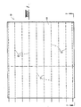
- Fig. 1 is a plan view of a building to be erected according to the principles of the present invention;
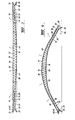
- Fig. 2 is a side view along and in the direction of arrows 2-2 of a truss forming part of the building shown in Fig. 1, before erection;
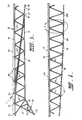
- Fig. 3 is a side view of an end section of the truss shown in Fig. 2;
- Fig. 4 is a side view of a part of the intermediate section of the truss shown in Fig. 2;
- Fig. 5 is an enlarged view of the circled area "5" in Fig. 4;
- Fig. 6 is a cross-sectional view along and in the direction of arrows 6-6 in Fig. 5;
- Fig. 7 is a view taken in the direction of arrow "7" shown in Fig. 3;
- Fig. 8 is a view similar to Fig. 6 showing the lateral buckling restraint for the truss;
- Fig. 9 is a view similar to that of Fig. 2 showing the truss in a partly-erected position; and
- Fig. 10 shows the truss in its fully erected position with tensioned external cables.
- In the drawings there is shown a
building 10 formed using a plurality oftrusses 12. Eachtruss 12 includes twoend sections 14 and anintermediate section 16. Theend sections 14 are rigid and form the wall of the completed building. Each end section is formed of anupper chord 18 and alower chord 20. The upper andlower chords diagonal web members 22 configured in a zig-zag fashion. In this embodiment the upper chord is formed by a pair ofrigid tubes 18A, 18B with the lower chord being formed from a channel section. The number and shape of the sections forming the upper and lower chords can vary depending on requirements. - At each end of the
end sections 14 are groundengaging points triangular framework 28 comprising anangular extension 30 oflower chord 20,strut member 32 anddiagonal web member 22. Additional strengthening struts 34 complete the triangular framework. - The
intermediate section 16 comprises anupper chord 36 and alower chord 38. Theupper chord 36 is continuous extension of theupper chords 18 ofend sections 14 and as described previously the upper chord is formed of a pair oftubes tube web 39 for structural integrity.Lower chord 38 is formed from twodiscontinuous tubes diameter end sections 40. Although this embodiment uses twotubes tubes upper chord 36 by insertion inrectangular mode connectors 42 which are secured todiagonal web members 44. To complete the intermediate sectionhigh tension cables tubes - As can be seen from Figs. 2 and 4
lower chord 38 is upwardly bowed in its assembled condition.Cables intermediate section 16 at point A (see Fig. 3) and enteringtubing lower chords end sections 14.Tension anchoring points end sections 14 toanchor cables - For lateral stability of the
trusses 12 when coupled together to form a building,bracing 58 can be provided at selected positions on theintermediate section 16 and/orend sections 14. Fig. 8 illustrates a preferred embodiment for providing lateral stability on theintermediate section 16. Twotrusses 12 each have acleat 60 secured thereto andpurlins 62 are attached between adjacent cleats byfasteners 64. Fig. 8. Thepurlins 62 are located below the upper surface of theupper chord 36 and allow, in the unstressed state, cladding 66 to rest thereon. Cladding 66 is secured totubes fly brace 70 is attached at one end tolower chord 38 and at the other end to purlin 62.Tension ties lower chords diagonal web members 44 so as to permit the consequential decrease in the truss depth (normal to the upper chord) as the lower chords shorten during erection. Thefree ends 76 and 78 oftension ties -
Cladding 66 is secured to theend sections 14 by girts 80 (Figs. 3 and 7) which are attached tocleats 82 onupper chord 18. Girts 80 lie above the upper surface ofupper chord 18 which allows the use of conventional wall bracing for stiffening. Cladding 66 is unstressed in this region. This positioning is in contrast to that previously described forpurlins 62 where the purlins are below and within the upper chord with the preferred position such that the upper edge of the purlins are at or near the neutral axis of theupper chord 36. This situates the intermediate section cladding so as to be axially compressed during and by the erection process. The curved, axially compressed cladding, when properly affixed to the purlins and truss system stiffens the roof against general instability during erection, tends to support itself, and transfers some of its weight off the truss to the columns thereby reducing the load on the truss system and distributes loads applied in a directional normal to the plane of the truss during its working life. - The erection of a building made using the trusses of the present invention will now be described. The
trusses 12 are assembled on site and laid parallel one with another as shown in Figs. 1 and 2. Thetubes cables tension anchoring points bracings 58 whilst in the position shown in Fig. 2. A significant advantage of the present invention is that the assembly takes place at ground level thus reducing industrial accidents resulting from working at heights. The electrical installation work can also be performed at this time allowing considerable savings in time to be achieved. At the left had side of Fig. 1ground engaging points 26 are pivotally pinned to stationary ground base plates (not shown). - The trusses are raised by the combined actions of an upwards force exerted upon the
intermediate section 16 by the tensioning of the downwardlycurved tension cables rigid end section 14 exerted by the pulling together of the ends of trusses by a temporary horizontal cable 84 (Fig. 9) at or just above ground level. The non-pivotted ground engaging points will slide along the ground and the truss will be lifted into the position shown in Fig. 9. The continued elevation of theintermediate section 16 is achieved by the controlled upwards buckling of theupper chord 36 restrained by the downwards force exerted on the truss by the upwards curvedtension cables end sections 14 produced by the pulling together of thepoints 26 by thehorizontal cable 84. Thetubes tubes intermediate section 16 then stiffens up as no further flexure is permitted. The dotted line on Fig. 1 indicates the final width of the building. Theintermediate section 16 may be further stiffened by the pre-compression of thelower chord tubes high strength cables cables - In practice the invention can provide a building at least 10 storeys high which is suitable for aircraft and airship hangars. In view of the large undercover area achieved by the invention and the low cost involved the invention can be used to cover areas which could not previously be considered cost-effective.
- It is believed that the invention and many of its attendant advantages will be understood from the foregoing description and it will be apparent that various changes may be made in the form, construction and arrangement of the parts and that changes may be made in the form, construction and arrangement of the truss described without departing from the spirit and scope of the invention or sacrificing all of its material advantages, the form hereinbefore described being merely a preferred embodiment thereof.
Claims (13)
Priority Applications (1)
| Application Number | Priority Date | Filing Date | Title |
|---|---|---|---|
| AT86304211T ATE60390T1 (en) | 1986-03-13 | 1986-06-03 | BUILDING TISSUE. |
Applications Claiming Priority (2)
| Application Number | Priority Date | Filing Date | Title |
|---|---|---|---|
| AU5022/86 | 1986-03-13 | ||
| AUPH502286 | 1986-03-13 |
Publications (3)
| Publication Number | Publication Date |
|---|---|
| EP0237667A2 true EP0237667A2 (en) | 1987-09-23 |
| EP0237667A3 EP0237667A3 (en) | 1988-02-03 |
| EP0237667B1 EP0237667B1 (en) | 1991-01-23 |
Family
ID=3771515
Family Applications (1)
| Application Number | Title | Priority Date | Filing Date |
|---|---|---|---|
| EP86304211A Expired - Lifetime EP0237667B1 (en) | 1986-03-13 | 1986-06-03 | Building truss |
Country Status (9)
| Country | Link |
|---|---|
| US (1) | US4890429A (en) |
| EP (1) | EP0237667B1 (en) |
| JP (1) | JPH0637790B2 (en) |
| KR (1) | KR910008081B1 (en) |
| CN (2) | CN1011807B (en) |
| AT (1) | ATE60390T1 (en) |
| CA (1) | CA1287729C (en) |
| DE (1) | DE3677198D1 (en) |
| NZ (1) | NZ218222A (en) |
Cited By (6)
| Publication number | Priority date | Publication date | Assignee | Title |
|---|---|---|---|---|
| AU588421B2 (en) * | 1986-01-31 | 1989-09-14 | Strarch Industries Pty. Ltd. | Structures |
| GB2281572A (en) * | 1991-05-31 | 1995-03-08 | Alfred Alphonse Yee | Truss for e.g. bridges |
| AT411472B (en) * | 2001-09-05 | 2004-01-26 | Poestinger Christian Ing | STRUCTURE |
| GB2431176A (en) * | 2004-07-21 | 2007-04-18 | S2 Holdings Pty Ltd | Building Methods |
| CN102733546A (en) * | 2012-07-06 | 2012-10-17 | 苏州工业园区设计研究院股份有限公司 | Large-span arch truss structure |
| US8607528B2 (en) | 2004-07-21 | 2013-12-17 | Murray Ellen | Building methods |
Families Citing this family (30)
| Publication number | Priority date | Publication date | Assignee | Title |
|---|---|---|---|---|
| JPH03295941A (en) * | 1990-04-13 | 1991-12-26 | Ohbayashi Corp | Arch shaped structure and construction thereof |
| JP2798819B2 (en) * | 1991-06-14 | 1998-09-17 | 飛島建設株式会社 | Dome construction method |
| JP2798820B2 (en) * | 1991-06-18 | 1998-09-17 | 飛島建設株式会社 | Truss manufacturing method and dome construction method using truss |
| DE4432251A1 (en) * | 1994-09-10 | 1996-05-30 | Dietmar Dipl Ing Dip Kallinich | Method of erecting curved support structure |
| US5701713A (en) * | 1996-03-29 | 1997-12-30 | Silver; Daniel J. | Adjustable truss |
| DE19837883C2 (en) * | 1998-08-20 | 2003-03-20 | Konrad Lehrhuber | Support device for building structures and method for producing a support device |
| GB0002519D0 (en) * | 2000-02-03 | 2000-03-29 | Univ Dundee | Cantilever support and erectable structures |
| AUPS171302A0 (en) * | 2002-04-12 | 2002-05-16 | Blazley, Wade Hylton | Roof structure |
| US6892502B1 (en) * | 2003-03-26 | 2005-05-17 | David A. Hubbell | Space frame support structure employing weld-free, single-cast structural connectors for highway signs |
| FR2857038B1 (en) * | 2003-07-03 | 2007-03-30 | Marc Edouard Irigoyen | BEAM ATTACHMENT SYSTEM |
| AU2005228911A1 (en) * | 2004-03-31 | 2005-10-13 | Strarch Technologies Pty Ltd | Modular structures |
| US8065762B1 (en) * | 2004-09-28 | 2011-11-29 | Jay Ewing | Hammock arch |
| CN101460685A (en) * | 2006-03-13 | 2009-06-17 | 洛克诺斯产品有限公司 | Panel building component and building shelter |
| CN100422468C (en) * | 2006-07-07 | 2008-10-01 | 贵州大学 | Large-span large-column distance quasi-ribbed floor type prestressed steel grid roof structure |
| US20080307719A1 (en) * | 2007-06-13 | 2008-12-18 | Murray Ellen | Domed non-steel roof frame |
| US20080307718A1 (en) * | 2007-06-13 | 2008-12-18 | Murray Ellen | Domed steel roof frame |
| CN101280613B (en) * | 2008-03-13 | 2010-06-09 | 边海波 | Girders assembling kit as well as girders and girders support system |
| AU2011232748B2 (en) * | 2011-10-05 | 2016-05-26 | Danpal Australia Pty Limited | Truss System |
| CN103174258B (en) * | 2013-02-28 | 2015-04-29 | 华南理工大学建筑设计研究院 | Antiskid device of beam string structure supporting rod |
| CN103114672B (en) * | 2013-03-08 | 2015-12-16 | 中铁五局(集团)有限公司 | A kind of steel truss arc canopy for high and cold permafrost tunnel hole |
| CN105064505B (en) * | 2015-08-06 | 2017-08-08 | 中国华西企业股份有限公司 | A kind of inverted triangle tubular truss and its construction method |
| CN105569187A (en) * | 2016-01-18 | 2016-05-11 | 江苏沪宁钢机股份有限公司 | Inverted arch beam string structure roof of large-span steel structure and construction method thereof |
| CN107974917B (en) * | 2017-11-15 | 2019-04-16 | 中铁大桥勘测设计院集团有限公司 | A kind of bending node, curve continuous steel girder bridge and its design method |
| CN108625530B (en) * | 2018-06-26 | 2024-01-19 | 上海天华建筑设计有限公司 | Beam string structure and construction method thereof |
| CN110104203B (en) * | 2019-05-16 | 2024-03-26 | 新誉集团有限公司 | Assembly positioning device and assembly method of carbon fiber truss for airship |
| CN112523357B (en) * | 2020-09-04 | 2022-06-17 | 浙大城市学院 | Steel supporting cylinder-lower hanging type truss system with arc-shaped vertical face and large open hole and application |
| CN112523358B (en) * | 2020-09-04 | 2022-06-17 | 浙大城市学院 | Bidirectional diagonal combination spoke type bracing cable truss system and application |
| CN112681521A (en) * | 2020-12-25 | 2021-04-20 | 海南大学 | Large-span swinging self-resetting structure |
| CN113775053A (en) * | 2021-09-27 | 2021-12-10 | 青岛新华友建工集团股份有限公司 | Large-span prestressed concrete frame beam hinge joint node structure |
| CN114000712A (en) * | 2021-11-24 | 2022-02-01 | 上海宝冶工程技术有限公司 | Large-span pipe truss structure downwarping deformation air slide rail system |
Citations (8)
| Publication number | Priority date | Publication date | Assignee | Title |
|---|---|---|---|---|
| BE516495A (en) * | ||||
| GB190902508A (en) * | 1908-02-11 | 1909-04-08 | Melvin Vaniman | Improvements in Shelters for Housing Dirigible Balloons. |
| CH378519A (en) * | 1960-04-21 | 1964-06-15 | Eggstein Julius | Tent hall construction |
| FR1445189A (en) * | 1965-08-23 | 1966-07-08 | Esslingen Maschf | Process for the erection of frames intended to support halls, tents, or the like and apparatus for carrying out this process |
| GB1202706A (en) * | 1967-05-09 | 1970-08-19 | Edwin Jacques Cohen | Arched building members |
| DE2342049A1 (en) * | 1973-08-20 | 1975-03-13 | Huurne Johannes Gerhardus Anto | Variable-load prestressed building element - core prestressed for tension and sheath prestressed for pressure or vice-versa |
| AU1078676A (en) * | 1975-02-13 | 1977-08-11 | Elspan International Ltd. | Roof structure |
| AU1237283A (en) * | 1982-03-15 | 1983-09-22 | Strarch Industries Pty. Ltd. | Trussed support for roof |
Family Cites Families (19)
| Publication number | Priority date | Publication date | Assignee | Title |
|---|---|---|---|---|
| US2415461A (en) * | 1947-02-11 | Scaffolding | ||
| US1915424A (en) * | 1928-03-14 | 1933-06-27 | Mcclintic Marshall Company | Metallic joist |
| US1985599A (en) * | 1931-11-19 | 1934-12-25 | Summerbell Truss Co | Roof construction |
| US2021480A (en) * | 1931-12-14 | 1935-11-19 | Davidson Louis | Arch construction |
| US2415240A (en) * | 1944-03-10 | 1947-02-04 | Michael A Fouhy | Process of erecting large span buildings |
| US2578465A (en) * | 1946-10-07 | 1951-12-11 | Davisbilt Steel Joist Inc | Metal joist |
| US2636457A (en) * | 1950-08-22 | 1953-04-28 | Boeing Co | Collapsible truss structure |
| US2793720A (en) * | 1951-12-24 | 1957-05-28 | Kwikform Ltd | Scaffolding and other structural elements |
| US2693195A (en) * | 1952-07-03 | 1954-11-02 | Frieder | Portable shelter |
| US3091313A (en) * | 1958-03-13 | 1963-05-28 | Dan L Colbath | Long span deck member |
| US3377637A (en) * | 1965-06-10 | 1968-04-16 | Zamorano Luis Ramirez | Pre-stressed truss |
| US3530622A (en) * | 1966-05-23 | 1970-09-29 | Edwin Jacques Cohen | Building apparatus and method |
| US3708944A (en) * | 1969-10-31 | 1973-01-09 | M Miyake | Method of making an arch |
| US3826057A (en) * | 1972-01-03 | 1974-07-30 | J Franklin | Truss system |
| US4275537A (en) * | 1977-05-26 | 1981-06-30 | Tension Structures, Inc. | Tension members |
| JPS5539513A (en) * | 1978-09-10 | 1980-03-19 | Yoshihiro Yonahara | Simply assembled structure |
| US4259825A (en) * | 1979-02-23 | 1981-04-07 | Nasa | Foldable beam |
| GB2051919B (en) * | 1979-06-02 | 1983-01-19 | Gleeson M | Stiffened elongate support member |
| US4393637A (en) * | 1980-10-10 | 1983-07-19 | Mosier Leo D | Wood roof truss construction |
-
1986
- 1986-06-03 AT AT86304211T patent/ATE60390T1/en not_active IP Right Cessation
- 1986-06-03 DE DE8686304211T patent/DE3677198D1/en not_active Expired - Lifetime
- 1986-06-03 EP EP86304211A patent/EP0237667B1/en not_active Expired - Lifetime
- 1986-06-13 JP JP61136347A patent/JPH0637790B2/en not_active Expired - Fee Related
- 1986-06-18 KR KR1019860004843A patent/KR910008081B1/en not_active IP Right Cessation
- 1986-06-25 CN CN86104405A patent/CN1011807B/en not_active Expired
- 1986-11-07 NZ NZ218222A patent/NZ218222A/en unknown
- 1986-11-12 CA CA000522804A patent/CA1287729C/en not_active Expired - Fee Related
-
1987
- 1987-11-24 US US07/135,490 patent/US4890429A/en not_active Expired - Lifetime
-
1989
- 1989-11-28 CN CN89109033A patent/CN1017173B/en not_active Expired
Patent Citations (8)
| Publication number | Priority date | Publication date | Assignee | Title |
|---|---|---|---|---|
| BE516495A (en) * | ||||
| GB190902508A (en) * | 1908-02-11 | 1909-04-08 | Melvin Vaniman | Improvements in Shelters for Housing Dirigible Balloons. |
| CH378519A (en) * | 1960-04-21 | 1964-06-15 | Eggstein Julius | Tent hall construction |
| FR1445189A (en) * | 1965-08-23 | 1966-07-08 | Esslingen Maschf | Process for the erection of frames intended to support halls, tents, or the like and apparatus for carrying out this process |
| GB1202706A (en) * | 1967-05-09 | 1970-08-19 | Edwin Jacques Cohen | Arched building members |
| DE2342049A1 (en) * | 1973-08-20 | 1975-03-13 | Huurne Johannes Gerhardus Anto | Variable-load prestressed building element - core prestressed for tension and sheath prestressed for pressure or vice-versa |
| AU1078676A (en) * | 1975-02-13 | 1977-08-11 | Elspan International Ltd. | Roof structure |
| AU1237283A (en) * | 1982-03-15 | 1983-09-22 | Strarch Industries Pty. Ltd. | Trussed support for roof |
Cited By (8)
| Publication number | Priority date | Publication date | Assignee | Title |
|---|---|---|---|---|
| AU588421B2 (en) * | 1986-01-31 | 1989-09-14 | Strarch Industries Pty. Ltd. | Structures |
| GB2281572A (en) * | 1991-05-31 | 1995-03-08 | Alfred Alphonse Yee | Truss for e.g. bridges |
| AT411472B (en) * | 2001-09-05 | 2004-01-26 | Poestinger Christian Ing | STRUCTURE |
| GB2431176A (en) * | 2004-07-21 | 2007-04-18 | S2 Holdings Pty Ltd | Building Methods |
| GB2431176B (en) * | 2004-07-21 | 2009-12-02 | S2 Holdings Pty Ltd | Building Methods |
| US8443572B2 (en) | 2004-07-21 | 2013-05-21 | S2 Holdings Pty Limited | Building methods |
| US8607528B2 (en) | 2004-07-21 | 2013-12-17 | Murray Ellen | Building methods |
| CN102733546A (en) * | 2012-07-06 | 2012-10-17 | 苏州工业园区设计研究院股份有限公司 | Large-span arch truss structure |
Also Published As
| Publication number | Publication date |
|---|---|
| ATE60390T1 (en) | 1991-02-15 |
| JPS62220636A (en) | 1987-09-28 |
| NZ218222A (en) | 1989-08-29 |
| KR910008081B1 (en) | 1991-10-07 |
| CA1287729C (en) | 1991-08-20 |
| CN1011807B (en) | 1991-02-27 |
| CN1017173B (en) | 1992-06-24 |
| CN86104405A (en) | 1987-10-28 |
| EP0237667A3 (en) | 1988-02-03 |
| DE3677198D1 (en) | 1991-02-28 |
| KR870009088A (en) | 1987-10-23 |
| US4890429A (en) | 1990-01-02 |
| JPH0637790B2 (en) | 1994-05-18 |
| CN1043182A (en) | 1990-06-20 |
| EP0237667B1 (en) | 1991-01-23 |
Similar Documents
| Publication | Publication Date | Title |
|---|---|---|
| EP0237667B1 (en) | Building truss | |
| US5146719A (en) | Space tension chord arch dome reinforced with tension members and method for building same | |
| US5159790A (en) | Frame structure | |
| AU2020213393B2 (en) | Beam system and method of erecting a supporting arch | |
| US4676045A (en) | Post-tensioned steel structure | |
| WO1994015041A1 (en) | Precision structural system | |
| CN216340448U (en) | Brace beam string beam | |
| US4052834A (en) | Method of erecting a roof structure | |
| US2878498A (en) | Bridge construction | |
| WO1990012167A1 (en) | Frame structure | |
| US4947599A (en) | Trussed girder with pre-tension member therein | |
| AU594056B2 (en) | Building truss | |
| JP3061560B2 (en) | Tent warehouse and its construction method | |
| WO1990013715A1 (en) | Lift arch building system | |
| WO1990005220A1 (en) | Adjustable space frames and trusses | |
| JPH03103560A (en) | Truss structure | |
| AU640658B2 (en) | Lift arch building system | |
| JP3252675B2 (en) | All-weather temporary roof | |
| RU2767619C1 (en) | Structural element (embodiments) | |
| JP2984700B2 (en) | Control method of installation distance in lift-up method of beam string | |
| JPS6114300B2 (en) | ||
| JP2761792B2 (en) | Construction method of large space building | |
| AU630127B2 (en) | Adjustable space frames and trusses | |
| CN116043699A (en) | Construction method of steel truss girder arch bridge | |
| RU2163962C2 (en) | Method and form for erecting bearing structures |
Legal Events
| Date | Code | Title | Description |
|---|---|---|---|
| PUAI | Public reference made under article 153(3) epc to a published international application that has entered the european phase |
Free format text: ORIGINAL CODE: 0009012 |
|
| AK | Designated contracting states |
Kind code of ref document: A2 Designated state(s): AT BE CH DE FR GB IT LI LU NL SE |
|
| PUAL | Search report despatched |
Free format text: ORIGINAL CODE: 0009013 |
|
| AK | Designated contracting states |
Kind code of ref document: A3 Designated state(s): AT BE CH DE FR GB IT LI LU NL SE |
|
| 17P | Request for examination filed |
Effective date: 19880419 |
|
| 17Q | First examination report despatched |
Effective date: 19890619 |
|
| GRAA | (expected) grant |
Free format text: ORIGINAL CODE: 0009210 |
|
| AK | Designated contracting states |
Kind code of ref document: B1 Designated state(s): AT BE CH DE FR GB IT LI LU NL SE |
|
| REF | Corresponds to: |
Ref document number: 60390 Country of ref document: AT Date of ref document: 19910215 Kind code of ref document: T |
|
| ITF | It: translation for a ep patent filed |
Owner name: JACOBACCI & PERANI S.P.A. |
|
| REF | Corresponds to: |
Ref document number: 3677198 Country of ref document: DE Date of ref document: 19910228 |
|
| ET | Fr: translation filed | ||
| PG25 | Lapsed in a contracting state [announced via postgrant information from national office to epo] |
Ref country code: LU Free format text: LAPSE BECAUSE OF NON-PAYMENT OF DUE FEES Effective date: 19910630 |
|
| PLBE | No opposition filed within time limit |
Free format text: ORIGINAL CODE: 0009261 |
|
| STAA | Information on the status of an ep patent application or granted ep patent |
Free format text: STATUS: NO OPPOSITION FILED WITHIN TIME LIMIT |
|
| 26N | No opposition filed | ||
| EAL | Se: european patent in force in sweden |
Ref document number: 86304211.5 |
|
| REG | Reference to a national code |
Ref country code: GB Ref legal event code: IF02 |
|
| PGFP | Annual fee paid to national office [announced via postgrant information from national office to epo] |
Ref country code: AT Payment date: 20050411 Year of fee payment: 20 |
|
| PGFP | Annual fee paid to national office [announced via postgrant information from national office to epo] |
Ref country code: BE Payment date: 20050517 Year of fee payment: 20 |
|
| PGFP | Annual fee paid to national office [announced via postgrant information from national office to epo] |
Ref country code: GB Payment date: 20050526 Year of fee payment: 20 |
|
| PGFP | Annual fee paid to national office [announced via postgrant information from national office to epo] |
Ref country code: IT Payment date: 20050614 Year of fee payment: 20 |
|
| PGFP | Annual fee paid to national office [announced via postgrant information from national office to epo] |
Ref country code: SE Payment date: 20050616 Year of fee payment: 20 Ref country code: NL Payment date: 20050616 Year of fee payment: 20 |
|
| PGFP | Annual fee paid to national office [announced via postgrant information from national office to epo] |
Ref country code: FR Payment date: 20050617 Year of fee payment: 20 |
|
| REG | Reference to a national code |
Ref country code: GB Ref legal event code: PE20 |
|
| PGFP | Annual fee paid to national office [announced via postgrant information from national office to epo] |
Ref country code: DE Payment date: 20050629 Year of fee payment: 20 Ref country code: CH Payment date: 20050629 Year of fee payment: 20 |
|
| PG25 | Lapsed in a contracting state [announced via postgrant information from national office to epo] |
Ref country code: GB Free format text: LAPSE BECAUSE OF EXPIRATION OF PROTECTION Effective date: 20060602 |
|
| PG25 | Lapsed in a contracting state [announced via postgrant information from national office to epo] |
Ref country code: NL Free format text: LAPSE BECAUSE OF EXPIRATION OF PROTECTION Effective date: 20060603 |
|
| REG | Reference to a national code |
Ref country code: CH Ref legal event code: PL |
|
| NLV7 | Nl: ceased due to reaching the maximum lifetime of a patent |
Effective date: 20060603 |
|
| EUG | Se: european patent has lapsed | ||
| BE20 | Be: patent expired |
Owner name: *STRARCH INDUSTRIES PTY. LTD Effective date: 20060603 |