EP0237254B1 - Centrifugal separator arranged for discharge af a separated product with a predetermined concentration - Google Patents
Centrifugal separator arranged for discharge af a separated product with a predetermined concentration Download PDFInfo
- Publication number
- EP0237254B1 EP0237254B1 EP87301848A EP87301848A EP0237254B1 EP 0237254 B1 EP0237254 B1 EP 0237254B1 EP 87301848 A EP87301848 A EP 87301848A EP 87301848 A EP87301848 A EP 87301848A EP 0237254 B1 EP0237254 B1 EP 0237254B1
- Authority
- EP
- European Patent Office
- Prior art keywords
- chamber
- recirculation
- component
- flow
- rotor
- Prior art date
- Legal status (The legal status is an assumption and is not a legal conclusion. Google has not performed a legal analysis and makes no representation as to the accuracy of the status listed.)
- Expired
Links
Images


Classifications
-
- B—PERFORMING OPERATIONS; TRANSPORTING
- B04—CENTRIFUGAL APPARATUS OR MACHINES FOR CARRYING-OUT PHYSICAL OR CHEMICAL PROCESSES
- B04B—CENTRIFUGES
- B04B1/00—Centrifuges with rotary bowls provided with solid jackets for separating predominantly liquid mixtures with or without solid particles
- B04B1/04—Centrifuges with rotary bowls provided with solid jackets for separating predominantly liquid mixtures with or without solid particles with inserted separating walls
- B04B1/08—Centrifuges with rotary bowls provided with solid jackets for separating predominantly liquid mixtures with or without solid particles with inserted separating walls of conical shape
Definitions
- the present invention relates to centrifugal separators.
- the invention concerns a centrifugal separator comprising a rotor enclosing a separation chamber provided with an inlet for a mixture of components to be separated, a first outlet for another a separated component having a reduced sludge content and a second outlet for a separated, sludge enriched component, the second outlet having a flow restriction and means being arranged for recirculating some separated sludge enriched component having passed therethrough for said the recirculated component to flow again through the restriction, said recirculation means including one or more recirculation passages so dimensioned that the recirculation flow of the sludge enriched component decreased with increasing viscosity of said component and increases with decreasing viscosity of said component.
- a centrifugal separator as mentioned above has been proposed in the U.S.A. 4,162,760, and this separator has a rotor with outlet nozzles around its periphery for discharging the separated sludge enriched component.
- Located outside the rotor is a reception vessel with an overflow outlet and a bottom outlet, the latter being in communication with a passage for recirculating of part of the separated sludge enriched component back to the centrifuge rotor.
- the recirculation passage is so formed that it lets through a flow that increases with decreasing viscosity and decreases with increasing viscosity of the separated sludge enriched component.
- This arrangement is intended to provide a constant concentration of the separated sludge enriched component leaving the centrifugal separator through the overflow outlet of the reception vessel.
- the reception vessel has a relatively large volume which is unavoidable because it extends around the whole of the rotor. This means that the concentration control cannot be made as accurate as is desirable, since it takes substantial time for separated sludge enriched component to flow from the outlet nozzles of the separation chamber, to the viscosity sensitive recirculation passage at the bottom of the reception vessel. Furthermore, the known construction requires a large space and is expensive.
- centrifugal separator as set forth hereinabove, characterised by:
- the entire concentration control equipment may be arranged within the rotor. Furthermore, both the reception chamber and the recirculation chamber may have a very small total volume and may communicate directly with the separation chamber. A change of the concentration of the flow leaving the separation chamber through said second outlet will, as a result, immediately influence the viscosity sensitive flow in the recirculation passage or passages. As a consequence the concentration control will be very accurate.
- the means for maintaining the liquid surface at the desired level in the recirculation chamber may comprise paring members or the like. By means of such members the liquid level if required may be moved radially during the operation of the rotor. This can be performed for instance by moving the paring member radially within the centrifuge rotor, or by actuating an adjustable throttle valve in the liquid channel of the paring member to let a larger or smaller flow out through the paring member.
- the means for determining the liquid level therein is preferably constituted by an overflow outlet.
- This overflow outlet may either lead directly to a stationary collection vessel outside the centrifuge rotor or lead to an outlet chamber within the centrifuge rotor, from which it can be conducted away by means of a paring member or the like.
- the overflow outlet instead, leads to the aforementioned reception chamber, one and the same member being arranged to conduct separated sludge enriched component from the reception chamber and to transfer part of it to the recirculation chamber, the rest of it passing out of the centrifuge rotor.
- a paring member or the like is preferably used to conduct separated sludge enriched component from the reception chamber.
- the liquid level in the reception chamber may be moved radially during the operation of the rotor in the same manner as described above in connection with the liquid level in the recirculation chamber.
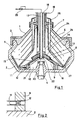
- FIG. 1 there is shown a centrifuge rotor composed by two parts 1 and 2, which are held together axially by means of a locking ring 3.
- the rotor is supported by a vertical drive shaft 4 connected with the rotor part 2.
- a separation chamber 5 in which a pile of conical separation discs 6 rest on the lower part of a so-called distributor 7, which in turn rests through radially extending wings 8 upon a partly conical partition 9 supported by the rotor part 2.
- a central chamber 10 Formed between the rotor part 2 and the partition 9 is a central chamber 10 which communicates through several radially extending pipes 11 connected to the partition 9 with the radially outermost parts of the separation chamber 5.
- Each pipe 11 has a throttle 12 at its radially innermost end.
- a further partition 13 with a smaller radial extension than the partition 9 is connected with the latter such that a radially inwardly open annular chamber 14 is formed between the partitions 9 and 13.
- the lower partition 9 has a central opening, and the annular edge of the partition 9 formed thereby constitutes an overflow outlet 15 from the chamber 14 to the chamber 10.
- the partition 13 also has a central opening, the diameter of which is smaller than that of the opening through the partition 9, however.
- the chamber 14 communicates through pipes 16 connected to the partition 13 with the radially outermost parts of the separation chamber 5.
- the pipes 11 and 16 are evenly distributed around the rotor axis, so that each pipe 11 is situated between two adjacent pipes 16.
- the pipes 11 have a substantially larger internal diameter than the pipes 16, and the throttles 12 of the pipes 11 (see Figure 2) are entirely responsible for determining the flow through the pipes 11.
- Each throttle 12 has a very small extension in the through-flow direction, so that changes expeceted during operation in the viscosity of a separated sludge enriched component flowing through the pipes 11 should not influence the through-flow to a substantial degree.
- each pipe 16 along the whole of its length has a through-flow area which is so small in relation to its length that flow of separated sludge enriched component through the pipes 16 is to a substantial degree influenced by the viscosity of the component.
- an increasing viscosity will result in a decreased flow through the pipes 16 if conditions are otherwise unchanged.
- Extending axially into the centrifuge rotor is a stationary member having one central channel 17 and two annular channels 18 and 19, respectively, surrounding coaxially the central channel.
- the central channel 17 constitutes an outlet channel and communicates through an opening 20 with the interior of a paring tube 21 extending into the chamber 10.
- a small opening 22 in the stationary member which provides for a small flow to pass from the channel 17 into the chamber 14.
- a constant pressure valve 23 shown schematically in Figure 1.
- a similar valve may be arranged in the outlet channel 19 for the separated liquid.
- the channel 18 constitutes an inlet channel and communicates through openings 24 with a central inlet chamber 25 in the rotor.
- the channel 19 constitutes an outlet channel and communicates with the interior of a paring disc 26.
- the central inlet chamber 25 communicates with the separation chamber 5 through the spaces between the radial wings 8 and through holes 27 in the lower part of the distributor 7.
- the embodiment according to Figure 1 is intended to operate in the following manner for the separation of sludge, for instance yeast, from a liquid.
- the mixture of sludge and liquid is introduced through the channel 18 into the rotor inlet chamber 25, from where it flows between the wings 8 and through the holes 27 to the separation chamber 5.
- the sludge is separated and collects at the radially outermost parts of the separation chamber, in the so-called sludge space, while the clarified liquid flows towards the rotor centre and is continuously discharged from the rotor through the paring disc 26 and the outlet channel 19.
- Sludge collected in the sludge space mixed with a small amount of liquid, flows radially inward through the so-called concentrate pipes 11 to the reception chamber 10, from which the sludge is pared off by the paring tube 21 and passes to the outlet channel 17 and out of the rotor.
- Some sludge passes from the outlet channel 17 through the hole 22 and enters the chamber 14. From there part of it flows further through the recirculation pipes 16 to the peripheral parts of the separation chamber 5, i.e. to the so-called sludge space, whereas excess sludge flows over the overflow outlet 15 back to the reception chamber 10.
- the constant pressure valve 23 is automatically controlled such that the free liquid surface in the reception chamber 10 is maintained by the paring tube 21 at a predetermined radial level. In a corresponding manner the free liquid surface of the clarified liquid is maintained in the rotor at a radial level closer to the rotor axis.
- the said transportation of sludge from the sludge space through the concentrate pipes 11 to the reception chamber 10 is accomplished.
- valve 23 maintains a constant pressure in the outlet channel 17, independently of the flow through the channel 17, a constant flow of sludge is obtained through the hole 22 to the recirculation chamber 14. It is assumed here that the extension of the hole 22 in the flow direction is so short that the flow therethrough is substantially independent of any changes occurring in the sludge viscosity.
- Figure 3 there is shown an alternative embodiment of the invention, according to which the reception chamber and the recirculation chamber are arranged at the top instead of at the bottom of the centrifuge rotor. Details in Figure 3 having counterparts in Figure 1 have been given the same reference numerals in Figure 3 with the addition of the letter "a".
- An additional member in this embodiment is constituted by a conical so-called top disc 28 having a larger radial extension than the separation discs 6a.
- the concentrate channels 11 a as well as the recirculation channels 16a are formed between the top disc 28 and the upper rotor part 1 a, for instance by radial grooves in the upper side of the top disc 28.
- Another additional member is constituted by an upper annular end wall 29 which is attached to the rotor part 1 by means of a locking ring 30.
- the end wall 29 forms with the partition 9a the reception chamber 10a.
- FIG. 31 forms together with the partition 9a the recirculation chamber 14a.
- the partition 32 forms an annular overflow outlet 33 from the separation chamber 5 to a paring chamber 34 surrounding the paring disc 26a for clarified liquid.
- a sludge containing liquid mixture is supplied to the rotor through the inlet channel 18a and flows through the reception chamber 25a and the holes 27a into the separation chamber 5a. Clarified liquid leaves the separation chamber 5a via the overflow outlet 33, the paring chamber 34, the paring disc 26a and the outlet channel 19a. Separated sludge flows from the sludge space through the concentrate channels 11 a and the throttles 12a into the reception chamber 10a, from where it is pared off by means of the paring disc 21a. Part of the sludge leaves the rotor through the outlet channel17a, while the rest of it is conducted through the opening 22a to the recirculation chamber 14a. Some of the sludge flows from there back to the sludge space through the recirculation channels 16a, while the rest flows across the overflow outlet 15a directly back to the reception chamber 1 Oa.
- FIG 4 there is shown a modification to part of the embodiment of Figure 3, the same reference numerals being used for corresponding details.
- One single member has been added in Figure 4, which is an annular slide 35.
- the slide can be turned around its own and the rotor axis.
- the slide 35 has a tubular part arranged radially between the annular walls defining the outlet channels 17a and 19a, respectively.
- At its lower end the tubular part of the slide 35 supports an external flange defining an annular groove 36 which opens upwards.
- Part of the member forming the outlet channel 17a extends down into this groove.
- the tubular part of the slide 35 has a radial through bore 37.
- the outer wall of the outlet channel 19a has a similar through bore 38.
- the radially outer wall of the channel 17a has a radial through bore constituting the previously mentioned passage 22a, through which part of the separated sludge enriched component can be transferred from the reception chamber 10a through the channel 17a to the recirculation chamber 14a.
- the radially outer side wall of the groove 36 has a corresponding through bore 39.
- the slide 35 is maintained in the position illustrated in Figure 4.
- the bores 22a and 39 are then aligned so that through-flow is possible from the channel 17a to the recirculation chamber 14a. Simultaneously the bore 38 is closed by the lower part of the slide 35.
- the slide 35 When the centrifuge rotor is to be cleaned, the slide 35 is turned through 180 ° about its axis, so that the lower bore 37 in the slide will be aligned with the bore 38, and the bore 22a is covered by a non-perforated part of the side wall of the groove 36.
- liquid having entered the reception chamber 10a from the radially outer parts of the separation chamber 5a is prevented from returning to the separation chamber through the recirculation chamber 14a and the channels 16a, and all such liquid is instead conducted out of the rotor through the outlet channel 17a.
- each throttle 12 ( Figure 1 and 2) or 12a ( Figure 3) may be substituted by a so-called vortex nozzle of the kind described in U.S.A. 4,311,270.
- a nozzle of this kind can be formed in a way such that a liquid flow therethrough increases with increasing viscosity of the liquid, and decreases with decreasing viscosity of the liquid.
Landscapes
- Centrifugal Separators (AREA)
Applications Claiming Priority (2)
| Application Number | Priority Date | Filing Date | Title |
|---|---|---|---|
| SE8601153 | 1986-03-12 | ||
| SE8601153A SE452260B (sv) | 1986-03-12 | 1986-03-12 | Centrifugalseparator anordnad for utmatning av en separerad produkt med bestemd koncentration |
Publications (2)
| Publication Number | Publication Date |
|---|---|
| EP0237254A1 EP0237254A1 (en) | 1987-09-16 |
| EP0237254B1 true EP0237254B1 (en) | 1990-10-31 |
Family
ID=20363804
Family Applications (1)
| Application Number | Title | Priority Date | Filing Date |
|---|---|---|---|
| EP87301848A Expired EP0237254B1 (en) | 1986-03-12 | 1987-03-03 | Centrifugal separator arranged for discharge af a separated product with a predetermined concentration |
Country Status (8)
| Country | Link |
|---|---|
| US (1) | US4729759A (sv) |
| EP (1) | EP0237254B1 (sv) |
| JP (1) | JPH0763652B2 (sv) |
| CN (1) | CN1007786B (sv) |
| BR (1) | BR8701112A (sv) |
| DE (1) | DE3765806D1 (sv) |
| SE (1) | SE452260B (sv) |
| SU (1) | SU1743339A3 (sv) |
Families Citing this family (29)
| Publication number | Priority date | Publication date | Assignee | Title |
|---|---|---|---|---|
| DE3627826C2 (de) * | 1986-08-16 | 1995-02-09 | Westfalia Separator Ag | Schleudertrommel |
| SE459159B (sv) * | 1987-10-08 | 1989-06-12 | Alfa Laval Separation Ab | Centrifugalseparator med utmatningsorgan |
| SE461019B (sv) * | 1988-05-02 | 1989-12-18 | Alfa Laval Marine Power Eng | Centrifugalseparator med ett pumporgan, inraettat foer att aastadkomma en cirkulation av vaetska i en stroemningskrets |
| JPH07114982B2 (ja) * | 1988-06-07 | 1995-12-13 | ヴェストファリア ゼパラトール アクチエンゲゼルシャフト | 遠心分離機 |
| DE3900796A1 (de) * | 1989-01-12 | 1990-07-19 | Asea Brown Boveri | Anordnung zur vermeidung der transformatorsaettigung bei betrieb an einem u-umrichter |
| US5300014A (en) * | 1992-10-16 | 1994-04-05 | Dorr-Oliver Corporation | Underflow control for nozzle centrifuges |
| DE19613215C1 (de) * | 1996-04-02 | 1997-09-25 | Westfalia Separator Ag | Schleudertrommel |
| US6312610B1 (en) | 1998-07-13 | 2001-11-06 | Phase Inc. | Density screening outer wall transport method for fluid separation devices |
| USRE38494E1 (en) | 1998-07-13 | 2004-04-13 | Phase Inc. | Method of construction for density screening outer transport walls |
| SE521366C2 (sv) * | 1998-08-24 | 2003-10-28 | Alfa Laval Corp Ab | Sätt och anordning för rengöring av en centrifugalseparator |
| SE520001C2 (sv) * | 1999-03-09 | 2003-05-06 | Alfa Laval Corp Ab | Låsring för en centrifugalseparator |
| US6755969B2 (en) | 2001-04-25 | 2004-06-29 | Phase Inc. | Centrifuge |
| US6805805B2 (en) * | 2001-08-13 | 2004-10-19 | Phase Inc. | System and method for receptacle wall vibration in a centrifuge |
| US6706180B2 (en) * | 2001-08-13 | 2004-03-16 | Phase Inc. | System for vibration in a centrifuge |
| EP1610879A4 (en) * | 2003-03-11 | 2007-02-21 | Phase Inc | CENTRIFUGE WITH CONTROLLED DISCHARGE OF SEALING MATERIAL |
| US6971525B2 (en) * | 2003-06-25 | 2005-12-06 | Phase Inc. | Centrifuge with combinations of multiple features |
| WO2005011833A2 (en) * | 2003-07-30 | 2005-02-10 | Phase Inc. | Filtration system with enhanced cleaning and dynamic fluid separation |
| EP1663459A4 (en) * | 2003-07-30 | 2007-11-07 | Phase Inc | FILTRATION SYSTEM AND DYNAMIC FLUID SEPARATION METHOD |
| US7282147B2 (en) * | 2003-10-07 | 2007-10-16 | Phase Inc. | Cleaning hollow core membrane fibers using vibration |
| SE526244C2 (sv) * | 2003-12-11 | 2005-08-02 | Alfa Laval Corp Ab | Centrifugalseparator |
| EP2091656A1 (en) * | 2006-11-15 | 2009-08-26 | Westfalia Separator Australia Pty.Ltd. | Continuous self-cleaning centrifuge assembly |
| DK2366457T3 (da) * | 2010-03-19 | 2013-06-10 | Alfa Laval Corp Ab | Anordning og fremgangsmåde til monitorering og justering af et grænsefladelags radiale position i en centrifuge |
| DE202010005476U1 (de) * | 2010-05-21 | 2011-09-08 | Gea Mechanical Equipment Gmbh | Separator |
| DE102010038193A1 (de) * | 2010-10-14 | 2012-04-19 | Gea Mechanical Equipment Gmbh | Verfahren zur Phasentrennung eines Produktes mit einer Zentrifuge |
| CN104870098B (zh) * | 2012-11-05 | 2018-08-10 | 美国血液技术公司 | 连续流动分离室 |
| DE102015101344A1 (de) * | 2015-01-29 | 2016-08-04 | Gea Mechanical Equipment Gmbh | Separator |
| JP5829352B1 (ja) * | 2015-07-31 | 2015-12-09 | 三菱化工機株式会社 | 排ガススクラバー用の遠心分離機及びその運転方法 |
| US11065376B2 (en) | 2018-03-26 | 2021-07-20 | Haemonetics Corporation | Plasmapheresis centrifuge bowl |
| CN109225676A (zh) * | 2018-10-16 | 2019-01-18 | 高根树 | 内旋转子固液离心分离装置 |
Family Cites Families (8)
| Publication number | Priority date | Publication date | Assignee | Title |
|---|---|---|---|---|
| DE1103258B (de) * | 1959-04-03 | 1961-03-23 | Separator Ab | Zentrifuge mit einer Schaeleinrichtung, deren Schaelkante in radialer Richtung verstellbar ist |
| US3204868A (en) * | 1960-06-06 | 1965-09-07 | Dorr Oliver Inc | Three-product nozzle-type centrifuge |
| NL284711A (sv) * | 1961-11-29 | |||
| CH451823A (de) * | 1966-05-23 | 1968-05-15 | Alfa Laval Ab | Verfahren zur stossfreien Einführung einer Flüssigkeit in eine Zentrifuge sowie Zentrifuge zur Ausführung des Verfahrens |
| US4067494A (en) * | 1977-01-03 | 1978-01-10 | Dorr-Oliver Incorporated | Nozzle type centrifugal machine with improved slurry pumping chambers |
| DE2701624C2 (de) * | 1977-01-17 | 1983-03-17 | Westfalia Separator Ag, 4740 Oelde | Kontinuierlich arbeitende Schleudertrommel zum Konzentrieren auspendierter Feststoffe |
| US4162760A (en) * | 1978-07-10 | 1979-07-31 | Pennwalt Corporation | Disc centrifuge with underflow discharge |
| DE2842967C2 (de) * | 1978-10-02 | 1984-08-16 | Westfalia Separator Ag, 4740 Oelde | Kontinuierlich arbeitende Schleudertrommel zum Konzentrieren suspendierter Feststoffe |
-
1986
- 1986-03-12 SE SE8601153A patent/SE452260B/sv not_active IP Right Cessation
-
1987
- 1987-02-20 US US07/016,740 patent/US4729759A/en not_active Expired - Lifetime
- 1987-03-03 DE DE8787301848T patent/DE3765806D1/de not_active Expired - Lifetime
- 1987-03-03 EP EP87301848A patent/EP0237254B1/en not_active Expired
- 1987-03-10 CN CN87101873A patent/CN1007786B/zh not_active Expired
- 1987-03-11 BR BR8701112A patent/BR8701112A/pt unknown
- 1987-03-11 SU SU874202131A patent/SU1743339A3/ru active
- 1987-03-12 JP JP62055475A patent/JPH0763652B2/ja not_active Expired - Lifetime
Also Published As
| Publication number | Publication date |
|---|---|
| JPH0763652B2 (ja) | 1995-07-12 |
| SE452260B (sv) | 1987-11-23 |
| EP0237254A1 (en) | 1987-09-16 |
| SU1743339A3 (ru) | 1992-06-23 |
| US4729759A (en) | 1988-03-08 |
| BR8701112A (pt) | 1987-12-29 |
| JPS62254857A (ja) | 1987-11-06 |
| SE8601153D0 (sv) | 1986-03-12 |
| CN1007786B (zh) | 1990-05-02 |
| CN87101873A (zh) | 1987-09-23 |
| SE8601153L (sv) | 1987-09-13 |
| DE3765806D1 (de) | 1990-12-06 |
Similar Documents
| Publication | Publication Date | Title |
|---|---|---|
| EP0237254B1 (en) | Centrifugal separator arranged for discharge af a separated product with a predetermined concentration | |
| EP0241128B1 (en) | Centrifugal separator with recirculation of separated sludge | |
| US4151950A (en) | Continuously operating centrifugal separator having hydraulically operated valves | |
| US5921909A (en) | Inlet device for a centrifugal separator | |
| JPH0716629B2 (ja) | 遠心分離機 | |
| US4505697A (en) | Underflow concentration control for nozzle centrifuges | |
| SE418459B (sv) | Centrifugalseparator | |
| US5941811A (en) | Centrifugal separator to free a liquid from both lighter particles and heavier particles | |
| US4354632A (en) | Operating system for centrifuges | |
| EP0312279B1 (en) | Centrifugal separator | |
| US5735789A (en) | Centrifugal separator | |
| JPH01130747A (ja) | 遠心分離機 | |
| US6319186B1 (en) | Method and a device for cleaning of a centrifugal separator | |
| JP2582845B2 (ja) | 遠心分離機 | |
| EP0616557B1 (en) | Centrifugal separator | |
| US3990632A (en) | Self-cleaning centrifugal separator with automatic control | |
| JPS6352945B2 (sv) | ||
| US3409214A (en) | Device for indicating the sludge level in sludge centrifuges | |
| US5897484A (en) | Centrifugal separator to free a liquid from bath lighter particles and heavier particles | |
| US2725186A (en) | Centrifuge for the clarification and standardization of milk | |
| WO1992007658A1 (en) | Centrifugal separator with receiving chamber for additional liquid | |
| SE454954B (sv) | Centrifugalseparator innefattande ett i utmatningskammaren anordnat stationert utmatningsorgan i form av en huvudsakligen cirkuler skiva |
Legal Events
| Date | Code | Title | Description |
|---|---|---|---|
| PUAI | Public reference made under article 153(3) epc to a published international application that has entered the european phase |
Free format text: ORIGINAL CODE: 0009012 |
|
| AK | Designated contracting states |
Kind code of ref document: A1 Designated state(s): CH DE FR GB IT LI NL SE |
|
| 17P | Request for examination filed |
Effective date: 19880106 |
|
| 17Q | First examination report despatched |
Effective date: 19881222 |
|
| GRAA | (expected) grant |
Free format text: ORIGINAL CODE: 0009210 |
|
| ITF | It: translation for a ep patent filed |
Owner name: BARZANO' E ZANARDO MILANO S.P.A. |
|
| AK | Designated contracting states |
Kind code of ref document: B1 Designated state(s): CH DE FR GB IT LI NL SE |
|
| PG25 | Lapsed in a contracting state [announced via postgrant information from national office to epo] |
Ref country code: SE Effective date: 19901031 |
|
| REF | Corresponds to: |
Ref document number: 3765806 Country of ref document: DE Date of ref document: 19901206 |
|
| ET | Fr: translation filed | ||
| ITTA | It: last paid annual fee | ||
| PLBE | No opposition filed within time limit |
Free format text: ORIGINAL CODE: 0009261 |
|
| STAA | Information on the status of an ep patent application or granted ep patent |
Free format text: STATUS: NO OPPOSITION FILED WITHIN TIME LIMIT |
|
| 26N | No opposition filed | ||
| PGFP | Annual fee paid to national office [announced via postgrant information from national office to epo] |
Ref country code: DE Payment date: 19991231 Year of fee payment: 14 |
|
| PGFP | Annual fee paid to national office [announced via postgrant information from national office to epo] |
Ref country code: GB Payment date: 20000301 Year of fee payment: 14 |
|
| PGFP | Annual fee paid to national office [announced via postgrant information from national office to epo] |
Ref country code: FR Payment date: 20000310 Year of fee payment: 14 |
|
| PGFP | Annual fee paid to national office [announced via postgrant information from national office to epo] |
Ref country code: CH Payment date: 20000313 Year of fee payment: 14 |
|
| PGFP | Annual fee paid to national office [announced via postgrant information from national office to epo] |
Ref country code: NL Payment date: 20000330 Year of fee payment: 14 |
|
| PG25 | Lapsed in a contracting state [announced via postgrant information from national office to epo] |
Ref country code: GB Free format text: LAPSE BECAUSE OF NON-PAYMENT OF DUE FEES Effective date: 20010303 |
|
| PG25 | Lapsed in a contracting state [announced via postgrant information from national office to epo] |
Ref country code: LI Free format text: LAPSE BECAUSE OF NON-PAYMENT OF DUE FEES Effective date: 20010331 Ref country code: CH Free format text: LAPSE BECAUSE OF NON-PAYMENT OF DUE FEES Effective date: 20010331 |
|
| PG25 | Lapsed in a contracting state [announced via postgrant information from national office to epo] |
Ref country code: NL Free format text: LAPSE BECAUSE OF NON-PAYMENT OF DUE FEES Effective date: 20011001 |
|
| GBPC | Gb: european patent ceased through non-payment of renewal fee |
Effective date: 20010303 |
|
| REG | Reference to a national code |
Ref country code: CH Ref legal event code: PL |
|
| PG25 | Lapsed in a contracting state [announced via postgrant information from national office to epo] |
Ref country code: FR Free format text: LAPSE BECAUSE OF NON-PAYMENT OF DUE FEES Effective date: 20011130 |
|
| NLV4 | Nl: lapsed or anulled due to non-payment of the annual fee |
Effective date: 20011001 |
|
| REG | Reference to a national code |
Ref country code: FR Ref legal event code: ST |
|
| PG25 | Lapsed in a contracting state [announced via postgrant information from national office to epo] |
Ref country code: DE Free format text: LAPSE BECAUSE OF NON-PAYMENT OF DUE FEES Effective date: 20020101 |
|
| PG25 | Lapsed in a contracting state [announced via postgrant information from national office to epo] |
Ref country code: IT Free format text: LAPSE BECAUSE OF NON-PAYMENT OF DUE FEES Effective date: 20050303 |