EP0236966B1 - Ablagefach für eine Belegverarbeitungseinrichtung zur Ablage von Belegen unterschiedlicher Grösse - Google Patents
Ablagefach für eine Belegverarbeitungseinrichtung zur Ablage von Belegen unterschiedlicher Grösse Download PDFInfo
- Publication number
- EP0236966B1 EP0236966B1 EP87103181A EP87103181A EP0236966B1 EP 0236966 B1 EP0236966 B1 EP 0236966B1 EP 87103181 A EP87103181 A EP 87103181A EP 87103181 A EP87103181 A EP 87103181A EP 0236966 B1 EP0236966 B1 EP 0236966B1
- Authority
- EP
- European Patent Office
- Prior art keywords
- pusher
- tray
- slide
- documents
- spring
- Prior art date
- Legal status (The legal status is an assumption and is not a legal conclusion. Google has not performed a legal analysis and makes no representation as to the accuracy of the status listed.)
- Expired
Links
Images
Classifications
-
- B—PERFORMING OPERATIONS; TRANSPORTING
- B65—CONVEYING; PACKING; STORING; HANDLING THIN OR FILAMENTARY MATERIAL
- B65H—HANDLING THIN OR FILAMENTARY MATERIAL, e.g. SHEETS, WEBS, CABLES
- B65H31/00—Pile receivers
- B65H31/20—Pile receivers adjustable for different article sizes
-
- G—PHYSICS
- G06—COMPUTING OR CALCULATING; COUNTING
- G06K—GRAPHICAL DATA READING; PRESENTATION OF DATA; RECORD CARRIERS; HANDLING RECORD CARRIERS
- G06K13/00—Conveying record carriers from one station to another, e.g. from stack to punching mechanism
- G06K13/02—Conveying record carriers from one station to another, e.g. from stack to punching mechanism the record carrier having longitudinal dimension comparable with transverse dimension, e.g. punched card
- G06K13/08—Feeding or discharging cards
- G06K13/14—Card magazines, e.g. pocket, hopper
Definitions
- the invention relates to a storage compartment according to the features of the preamble of claim 1.
- document processing devices for example form readers
- input and output compartments are expediently designed so that they can be adapted to different document sizes by means of easily adjustable stops.
- the present invention has for its object to provide a storage compartment that offers the greatest possible range of variation with respect to the storage of documents of different sizes.
- This object is achieved according to the invention by the characterizing features of claim 1.
- the advantage of this storage compartment with the two interlocking sliders is that starting from a medium document size by pulling out the first slider, a continuous adjustment to larger document formats and when the first slider is inserted by inserting the second slider additionally, an infinitely variable adjustment to smaller document formats can be achieved.
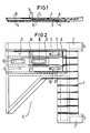
- Figures 1 and 2 show a sectional side view and a plan view of a storage compartment 1, which is suspended with the help of two wedge-shaped extension pieces 2, 3 in a housing opening of a document processing device, for example for a form reader, and held by engaging stop bars 4, 5.
- the storage compartment 1 has an essentially rectangular shape with, for example, a trapezoidal cutout 6 provided on one long side. This cutout 6 facilitates the removal of the documents insofar as the documents in the area of the cutout 6 can be grasped both from above and from below.
- the cutout 6 extends so far inwards that documents of a smaller format can be gripped on both sides.
- the recess also serves as a viewing window.
- a slider-like first slide 8 is provided in a longitudinal groove 7 of the storage compartment 1 and can be pulled out of the storage compartment 1 in a stepless manner when larger documents are being stored.
- the first slide 8 is guided, for example, like a dovetail and has two detent springs 9, 10 at the inserted end, which engage in correspondingly shaped detent points 11 in the longitudinal groove 7 in both settings of the slide 8.
- a stop bracket 14 is attached to the rear end of this second slide 13.
- the drawing shows the second slide 13, which is infinitely adjustable with respect to the first slide 8, in the inner end position, which can be considered when storing small documents.
- the storage compartment 1 with the two slides 8, 13 can thus be set to any document size between A4 and A7.
- the length of the storage compartment 1 corresponds to only half the length of the largest document to be processed, so that its dimensions are roughly equivalent to a DIN A5 format.
- wave-shaped leaf springs 15, 16 acting as brake springs are provided, which are arranged in flat spring troughs in the longitudinal groove 7 of the storage compartment 1 or on the underside of the second slider 13.
- the top surfaces of the two slides 8, 13 are otherwise flush with the top surfaces of the storage compartment 1, so that overall there is a flat contact surface.
Landscapes
- Engineering & Computer Science (AREA)
- Physics & Mathematics (AREA)
- General Physics & Mathematics (AREA)
- Theoretical Computer Science (AREA)
- Mechanical Engineering (AREA)
- Sheets, Magazines, And Separation Thereof (AREA)
- Drawers Of Furniture (AREA)
- Pile Receivers (AREA)
- Auxiliary Methods And Devices For Loading And Unloading (AREA)
- Details Of Indoor Wiring (AREA)
- Exposure Or Original Feeding In Electrophotography (AREA)
Description
- Die Erfindungbetrifft ein Ablagefach nach den Merkmalen des Oberbegriffs des Anspruchs 1.
- Angesichts der Vielfalt von Belegformaten und Beleggrößen sind Belegverarbeitungseinrichtungen, beispielsweise Formularlesegeräte vielfach bereits so universell konzipiert, daß eine Verarbeitung unterschiedlicher Belege ohne besondere Vorkehrungen problemlos durchführbar ist. Insbesondere die Ein- und Ausgabefächer sind zweckmäßig so gestaltet, daß sie durch leicht verstellbare Anschläge an unterschiedliche Beleggrößen angepaßt werden können.
- Der vorliegenden Erfindung liegt nun die Aufgabe zugrunde, ein Ablagefach zu schaffen, das in bezug auf die Ablage unterschiedlich großer Belege eine möglichst große Variationsbreite bietet.
- Die Lösung dieser Aufgabe ergibt sich erfindungsgemäß durch die kennzeichnenden Merkmale des Anspruchs 1. Der Vorteil dieses Ablagefaches mit den beiden ineinandergreifend angeordneten Schiebern besteht darin, daß ausgehend von einer mittleren Beleggröße durch Herausziehen des ersten Schiebers eine stufenlose Anpassung an größer Belegformate und bei eingeschobenem ersten Schieber durch zusätzliches Einschieben des zweiten Schiebers eine ebenfalls stufenlose Anpassung an kleinere Belegformate erreichbar ist.
- Vorteilhafte Weiterbildungen der Erfindungsind in den Unteransprüchen angegeben.
- Im folgenden wird ein Ausführungsbeispiel der Erfindung anhand der Zeichnung näher erläutert.
- Die Figuren 1 und 2 zeigen in einer geschnittenen Seitenansicht und in einer Draufsicht ein Ablagefach 1, das mit Hilfe zweier keilförmig zulaufender Ansatzstücke 2, 3 in eine Gehäuseöffnung einer Belegverarbeitungseinrichtung, beispielsweise für ein Formularlesegerät, eingehängt und durch hintergreifende Anschlagleisten 4, 5 gehalten wird. Das Ablagefach 1 hat eine im wesentlichen rechteckige Form mit einem an einer Längsseite vorgesehenen beispielsweise trapezförmigen Ausschnitt 6. Dieser Ausschnitt 6 erleichtert die Entnahme der Belege insofern, als die Belege im Bereich des Ausschnitts 6 sowohl von oben als auch von unten erfaßt werden können. Der Ausschnitt 6 reicht dabei so weit nach innen, daß auch Belege kleineren Formats beidseitig gefaßt werden können. Die Aussparung dient außerdem als Sichtfenster. Bei mehreren übereinander angeordneten Ablagefächern kann nämlich in der darunter befindlichen Ablagefächern leicht festgestellt werden, ob dort Belege abgelegt sind. Zur Anpassung an unterschiedliche Beleggrößen ist ein in einer Längsnut 7 des Ablagefaches 1 schlittenartig geführter erster Schieber 8 vorgesehen, der bei der Ablage größerer Belege aus dem Ablagefach 1 stufenlos herausgezogen werden kann. Deser erste Schieber 8 ist zum Beispiel schwalbenschwanzartig geführt und weist am eingeschobenen Ende zwei Rastfedern 9, 10 auf, die in beiden Einstellungen des Schiebers 8 in entsprechend ausgeformte Rastpunkte 11 in der Längsnut 7 eingreifen. Auf der Oberseite des ersten Schiebers 8 ist eine weitere Längsnut 12 vorgesehen, in der ein zweiter Schieber 13 geführt ist. Am hinteren Ende dieses zweiten Schiebers 13 ist ein Anschlagwinkel 14 angebracht. Die Zeichnung zeigt den gegenüber dem ersten Schieber 8 stufenlos verstellbaren zweiten Schieber 13 in der inneren Endstellung, die bei der Ablage von kleinen Belegen in Betracht kommt. Das Ablagefach 1 mit den beiden Schiebern 8, 13 ist somit auf beliebige Beleggrößen zwischen DIN A4 und DIN A7 einstellbar. Die Länge des Ablagefachs 1 entspricht aber nur der halben Länge des größten zu verarbeitenden Beleges, so daß es in seinen Abmessungen in etwa einem DIN A5-Format gleichkommt. An der Unterseite der beiden Schieber 8, 13 sind wellenförmig gebogene, als Bremsfedern wirkende Blattfedern 15, 16 vorgsehen, die in flachen Federwannen in der Längsnut 7 des Ablagefachs 1 bzw. an der Unterseite des zweiten Schiebers 13 angeordnet sind. Die Deckflächen der beiden Schieber 8, 13 verlaufen im übrigen bündig zu den Deckflächen des Ablagefaches 1, so daß sich insgesamt eine ebene Auflagefläche ergibt.
Claims (4)
Priority Applications (1)
| Application Number | Priority Date | Filing Date | Title |
|---|---|---|---|
| AT87103181T ATE45329T1 (de) | 1986-03-11 | 1987-03-06 | Ablagefach fuer eine belegverarbeitungseinrichtung zur ablage von belegen unterschiedlicher groesse. |
Applications Claiming Priority (2)
| Application Number | Priority Date | Filing Date | Title |
|---|---|---|---|
| DE8606645U | 1986-03-11 | ||
| DE8606645U DE8606645U1 (de) | 1986-03-11 | 1986-03-11 | Ablagefach für eine Belegverarbeitungseinrichtung zur Ablage von Belegen unterschiedlicher Größe |
Publications (2)
| Publication Number | Publication Date |
|---|---|
| EP0236966A1 EP0236966A1 (de) | 1987-09-16 |
| EP0236966B1 true EP0236966B1 (de) | 1989-08-09 |
Family
ID=6792592
Family Applications (1)
| Application Number | Title | Priority Date | Filing Date |
|---|---|---|---|
| EP87103181A Expired EP0236966B1 (de) | 1986-03-11 | 1987-03-06 | Ablagefach für eine Belegverarbeitungseinrichtung zur Ablage von Belegen unterschiedlicher Grösse |
Country Status (5)
| Country | Link |
|---|---|
| US (1) | US4773638A (de) |
| EP (1) | EP0236966B1 (de) |
| AT (1) | ATE45329T1 (de) |
| DE (2) | DE8606645U1 (de) |
| ES (1) | ES2009809B3 (de) |
Families Citing this family (7)
| Publication number | Priority date | Publication date | Assignee | Title |
|---|---|---|---|---|
| DE3906984A1 (de) * | 1989-03-04 | 1990-09-06 | Kodak Ag | Vorratsbehaelter fuer gestapelte blaetter |
| DE4030643A1 (de) * | 1990-09-27 | 1992-04-09 | Gaemmerler Hagen | Verfahren und vorrichtung zum ablegen und transportieren von flaechengebilden |
| US5908189A (en) * | 1997-04-21 | 1999-06-01 | Lexmark International, Inc. | Paper stack height control |
| JP4160362B2 (ja) * | 2002-10-30 | 2008-10-01 | グローリー株式会社 | 集積装置および循環式紙幣入出金機 |
| US7034362B2 (en) * | 2003-10-17 | 2006-04-25 | International Business Machines Corporation | Double silicon-on-insulator (SOI) metal oxide semiconductor field effect transistor (MOSFET) structures |
| US7540372B2 (en) * | 2006-01-05 | 2009-06-02 | Ecrm, Inc. | Belt driven and roller assisted media transport |
| US9284136B1 (en) * | 2014-12-17 | 2016-03-15 | Hewlett-Packard Development Company, L.P. | Media guide |
Family Cites Families (5)
| Publication number | Priority date | Publication date | Assignee | Title |
|---|---|---|---|---|
| US1221831A (en) * | 1913-07-10 | 1917-04-10 | Burt Co Ltd F N | Labeling-machine. |
| US1987803A (en) * | 1934-07-28 | 1935-01-15 | Nat Pestal Meter Company | Adjustable magazine |
| US4032136A (en) * | 1973-04-06 | 1977-06-28 | Canon Kabushiki Kaisha | Feed cassette |
| JPS5269625A (en) * | 1975-12-09 | 1977-06-09 | Fuji Xerox Co Ltd | Sheet container for copying machine |
| JPS5465972A (en) * | 1977-11-04 | 1979-05-28 | Konishiroku Photo Ind | Paper feeder |
-
1986
- 1986-03-11 DE DE8606645U patent/DE8606645U1/de not_active Expired
-
1987
- 1987-03-06 DE DE8787103181T patent/DE3760410D1/de not_active Expired
- 1987-03-06 EP EP87103181A patent/EP0236966B1/de not_active Expired
- 1987-03-06 AT AT87103181T patent/ATE45329T1/de not_active IP Right Cessation
- 1987-03-06 ES ES87103181T patent/ES2009809B3/es not_active Expired
- 1987-03-11 US US07/024,793 patent/US4773638A/en not_active Expired - Fee Related
Also Published As
| Publication number | Publication date |
|---|---|
| ES2009809B3 (es) | 1989-10-16 |
| EP0236966A1 (de) | 1987-09-16 |
| DE8606645U1 (de) | 1986-04-30 |
| DE3760410D1 (en) | 1989-09-14 |
| ATE45329T1 (de) | 1989-08-15 |
| US4773638A (en) | 1988-09-27 |
Similar Documents
| Publication | Publication Date | Title |
|---|---|---|
| EP0203168B1 (de) | Behälter für einen blattstapel | |
| DE2255076A1 (de) | Verstellbarer stuhl | |
| DE69314418T2 (de) | Rippenmatte für Aktenschrank | |
| EP0236966A1 (de) | Ablagefach für eine Belegverarbeitungseinrichtung zur Ablage von Belegen unterschiedlicher Grösse | |
| DE2647067C3 (de) | Merkblattregister | |
| EP0576111B1 (de) | Sammelmappe | |
| DE1246195B (de) | Fuehrung fuer Schubkaesten | |
| DE3879945T2 (de) | Behältnis zum aufbewahren von zeitungen oder dgl. | |
| EP0121710A2 (de) | Einsatz für eine Kassenschublade | |
| EP0237026A1 (de) | Belegverarbeitungseinrichtung für Belege unterschiedlichen Formats | |
| DE148357C (de) | ||
| DE3306987C2 (de) | Briefordnermechanik | |
| EP0279256A2 (de) | Brieflocher mit Anschlagschiene | |
| DE182213C (de) | ||
| EP0560301B1 (de) | Kassenlade | |
| DE1536559C3 (de) | Aufbewahrungsgerät für Visitenkarten | |
| DE518816C (de) | Behaelter fuer flache Gegenstaende, Schallplatten o. dgl. | |
| DE1204191B (de) | Ordnerkasten | |
| DE196353C (de) | ||
| DE8630610U1 (de) | Regalmöbel | |
| DE156026C (de) | ||
| DE3217189A1 (de) | Vorrichtung zur aufbewahrung und praesentation von ein- oder mehrblaettrigen drucksachen | |
| DE202006001783U1 (de) | Sturzkasten für Backteiglinge | |
| DE1245312B (de) | Ordner zum Einhaengen von Schriftgut | |
| DE8112541U1 (de) | Adapter |
Legal Events
| Date | Code | Title | Description |
|---|---|---|---|
| PUAI | Public reference made under article 153(3) epc to a published international application that has entered the european phase |
Free format text: ORIGINAL CODE: 0009012 |
|
| AK | Designated contracting states |
Kind code of ref document: A1 Designated state(s): AT BE CH DE ES FR GB IT LI NL SE |
|
| 17P | Request for examination filed |
Effective date: 19871007 |
|
| 17Q | First examination report despatched |
Effective date: 19881111 |
|
| GRAA | (expected) grant |
Free format text: ORIGINAL CODE: 0009210 |
|
| AK | Designated contracting states |
Kind code of ref document: B1 Designated state(s): AT BE CH DE ES FR GB IT LI NL SE |
|
| REF | Corresponds to: |
Ref document number: 45329 Country of ref document: AT Date of ref document: 19890815 Kind code of ref document: T |
|
| REF | Corresponds to: |
Ref document number: 3760410 Country of ref document: DE Date of ref document: 19890914 |
|
| ITF | It: translation for a ep patent filed | ||
| ET | Fr: translation filed | ||
| GBT | Gb: translation of ep patent filed (gb section 77(6)(a)/1977) | ||
| PLBE | No opposition filed within time limit |
Free format text: ORIGINAL CODE: 0009261 |
|
| STAA | Information on the status of an ep patent application or granted ep patent |
Free format text: STATUS: NO OPPOSITION FILED WITHIN TIME LIMIT |
|
| 26N | No opposition filed | ||
| ITTA | It: last paid annual fee | ||
| PGFP | Annual fee paid to national office [announced via postgrant information from national office to epo] |
Ref country code: AT Payment date: 19940223 Year of fee payment: 8 |
|
| PGFP | Annual fee paid to national office [announced via postgrant information from national office to epo] |
Ref country code: BE Payment date: 19940308 Year of fee payment: 8 |
|
| PGFP | Annual fee paid to national office [announced via postgrant information from national office to epo] |
Ref country code: FR Payment date: 19940317 Year of fee payment: 8 Ref country code: ES Payment date: 19940317 Year of fee payment: 8 |
|
| PGFP | Annual fee paid to national office [announced via postgrant information from national office to epo] |
Ref country code: SE Payment date: 19940324 Year of fee payment: 8 |
|
| PGFP | Annual fee paid to national office [announced via postgrant information from national office to epo] |
Ref country code: NL Payment date: 19940331 Year of fee payment: 8 |
|
| PGFP | Annual fee paid to national office [announced via postgrant information from national office to epo] |
Ref country code: CH Payment date: 19940617 Year of fee payment: 8 |
|
| EAL | Se: european patent in force in sweden |
Ref document number: 87103181.1 |
|
| PG25 | Lapsed in a contracting state [announced via postgrant information from national office to epo] |
Ref country code: AT Effective date: 19950306 |
|
| PG25 | Lapsed in a contracting state [announced via postgrant information from national office to epo] |
Ref country code: SE Effective date: 19950307 Ref country code: ES Free format text: LAPSE BECAUSE OF NON-PAYMENT OF DUE FEES Effective date: 19950307 |
|
| PG25 | Lapsed in a contracting state [announced via postgrant information from national office to epo] |
Ref country code: LI Effective date: 19950331 Ref country code: CH Effective date: 19950331 Ref country code: BE Effective date: 19950331 |
|
| BERE | Be: lapsed |
Owner name: COMPUTER G.- KONSTANZ M.B.H. Effective date: 19950331 |
|
| PG25 | Lapsed in a contracting state [announced via postgrant information from national office to epo] |
Ref country code: NL Effective date: 19951001 |
|
| PG25 | Lapsed in a contracting state [announced via postgrant information from national office to epo] |
Ref country code: FR Free format text: LAPSE BECAUSE OF NON-PAYMENT OF DUE FEES Effective date: 19951130 |
|
| REG | Reference to a national code |
Ref country code: CH Ref legal event code: PL |
|
| NLV4 | Nl: lapsed or anulled due to non-payment of the annual fee |
Effective date: 19951001 |
|
| EUG | Se: european patent has lapsed |
Ref document number: 87103181.1 |
|
| REG | Reference to a national code |
Ref country code: FR Ref legal event code: ST |
|
| PGFP | Annual fee paid to national office [announced via postgrant information from national office to epo] |
Ref country code: GB Payment date: 19980211 Year of fee payment: 12 |
|
| PGFP | Annual fee paid to national office [announced via postgrant information from national office to epo] |
Ref country code: DE Payment date: 19980519 Year of fee payment: 12 |
|
| PG25 | Lapsed in a contracting state [announced via postgrant information from national office to epo] |
Ref country code: GB Free format text: LAPSE BECAUSE OF NON-PAYMENT OF DUE FEES Effective date: 19990306 |
|
| REG | Reference to a national code |
Ref country code: ES Ref legal event code: FD2A Effective date: 19990201 |
|
| GBPC | Gb: european patent ceased through non-payment of renewal fee |
Effective date: 19990306 |
|
| PG25 | Lapsed in a contracting state [announced via postgrant information from national office to epo] |
Ref country code: DE Free format text: LAPSE BECAUSE OF NON-PAYMENT OF DUE FEES Effective date: 20000101 |
|
| PG25 | Lapsed in a contracting state [announced via postgrant information from national office to epo] |
Ref country code: IT Free format text: LAPSE BECAUSE OF NON-PAYMENT OF DUE FEES;WARNING: LAPSES OF ITALIAN PATENTS WITH EFFECTIVE DATE BEFORE 2007 MAY HAVE OCCURRED AT ANY TIME BEFORE 2007. THE CORRECT EFFECTIVE DATE MAY BE DIFFERENT FROM THE ONE RECORDED. Effective date: 20050306 |