EP0233302A1 - Fluidisches System mit Messvorrichtung - Google Patents
Fluidisches System mit Messvorrichtung Download PDFInfo
- Publication number
- EP0233302A1 EP0233302A1 EP86101980A EP86101980A EP0233302A1 EP 0233302 A1 EP0233302 A1 EP 0233302A1 EP 86101980 A EP86101980 A EP 86101980A EP 86101980 A EP86101980 A EP 86101980A EP 0233302 A1 EP0233302 A1 EP 0233302A1
- Authority
- EP
- European Patent Office
- Prior art keywords
- measuring device
- coupling
- socket
- piece
- housing
- Prior art date
- Legal status (The legal status is an assumption and is not a legal conclusion. Google has not performed a legal analysis and makes no representation as to the accuracy of the status listed.)
- Granted
Links
- 238000010168 coupling process Methods 0.000 claims abstract description 80
- 230000008878 coupling Effects 0.000 claims abstract description 69
- 238000005859 coupling reaction Methods 0.000 claims abstract description 69
- 238000007789 sealing Methods 0.000 claims abstract description 53
- 239000012530 fluid Substances 0.000 claims abstract description 26
- 210000002445 nipple Anatomy 0.000 claims abstract description 18
- 238000009423 ventilation Methods 0.000 claims abstract description 12
- 230000001105 regulatory effect Effects 0.000 claims abstract description 8
- 230000035515 penetration Effects 0.000 claims description 7
- 238000011144 upstream manufacturing Methods 0.000 claims description 6
- 239000013536 elastomeric material Substances 0.000 claims description 5
- 238000004891 communication Methods 0.000 claims description 2
- 230000003111 delayed effect Effects 0.000 claims description 2
- 238000005259 measurement Methods 0.000 description 8
- 238000012360 testing method Methods 0.000 description 7
- 239000007789 gas Substances 0.000 description 4
- 238000013461 design Methods 0.000 description 3
- 230000000694 effects Effects 0.000 description 3
- 238000000034 method Methods 0.000 description 3
- 238000011161 development Methods 0.000 description 2
- 238000010586 diagram Methods 0.000 description 2
- 230000000712 assembly Effects 0.000 description 1
- 238000000429 assembly Methods 0.000 description 1
- 238000009530 blood pressure measurement Methods 0.000 description 1
- 239000003795 chemical substances by application Substances 0.000 description 1
- 230000006835 compression Effects 0.000 description 1
- 238000007906 compression Methods 0.000 description 1
- 239000004020 conductor Substances 0.000 description 1
- 230000006378 damage Effects 0.000 description 1
- 230000002950 deficient Effects 0.000 description 1
- 238000003745 diagnosis Methods 0.000 description 1
- 239000010720 hydraulic oil Substances 0.000 description 1
- 238000002386 leaching Methods 0.000 description 1
- 239000007788 liquid Substances 0.000 description 1
- 238000004519 manufacturing process Methods 0.000 description 1
- 230000001681 protective effect Effects 0.000 description 1
- 239000004065 semiconductor Substances 0.000 description 1
- 239000000126 substance Substances 0.000 description 1
Images


Classifications
-
- G—PHYSICS
- G01—MEASURING; TESTING
- G01L—MEASURING FORCE, STRESS, TORQUE, WORK, MECHANICAL POWER, MECHANICAL EFFICIENCY, OR FLUID PRESSURE
- G01L19/00—Details of, or accessories for, apparatus for measuring steady or quasi-steady pressure of a fluent medium insofar as such details or accessories are not special to particular types of pressure gauges
- G01L19/0007—Fluidic connecting means
- G01L19/0015—Fluidic connecting means using switching means
-
- F—MECHANICAL ENGINEERING; LIGHTING; HEATING; WEAPONS; BLASTING
- F16—ENGINEERING ELEMENTS AND UNITS; GENERAL MEASURES FOR PRODUCING AND MAINTAINING EFFECTIVE FUNCTIONING OF MACHINES OR INSTALLATIONS; THERMAL INSULATION IN GENERAL
- F16L—PIPES; JOINTS OR FITTINGS FOR PIPES; SUPPORTS FOR PIPES, CABLES OR PROTECTIVE TUBING; MEANS FOR THERMAL INSULATION IN GENERAL
- F16L39/00—Joints or fittings for double-walled or multi-channel pipes or pipe assemblies
- F16L39/02—Joints or fittings for double-walled or multi-channel pipes or pipe assemblies for hoses
-
- F—MECHANICAL ENGINEERING; LIGHTING; HEATING; WEAPONS; BLASTING
- F16—ENGINEERING ELEMENTS AND UNITS; GENERAL MEASURES FOR PRODUCING AND MAINTAINING EFFECTIVE FUNCTIONING OF MACHINES OR INSTALLATIONS; THERMAL INSULATION IN GENERAL
- F16N—LUBRICATING
- F16N2250/00—Measuring
-
- Y—GENERAL TAGGING OF NEW TECHNOLOGICAL DEVELOPMENTS; GENERAL TAGGING OF CROSS-SECTIONAL TECHNOLOGIES SPANNING OVER SEVERAL SECTIONS OF THE IPC; TECHNICAL SUBJECTS COVERED BY FORMER USPC CROSS-REFERENCE ART COLLECTIONS [XRACs] AND DIGESTS
- Y10—TECHNICAL SUBJECTS COVERED BY FORMER USPC
- Y10T—TECHNICAL SUBJECTS COVERED BY FORMER US CLASSIFICATION
- Y10T137/00—Fluid handling
- Y10T137/8158—With indicator, register, recorder, alarm or inspection means
- Y10T137/8326—Fluid pressure responsive indicator, recorder or alarm
-
- Y—GENERAL TAGGING OF NEW TECHNOLOGICAL DEVELOPMENTS; GENERAL TAGGING OF CROSS-SECTIONAL TECHNOLOGIES SPANNING OVER SEVERAL SECTIONS OF THE IPC; TECHNICAL SUBJECTS COVERED BY FORMER USPC CROSS-REFERENCE ART COLLECTIONS [XRACs] AND DIGESTS
- Y10—TECHNICAL SUBJECTS COVERED BY FORMER USPC
- Y10T—TECHNICAL SUBJECTS COVERED BY FORMER US CLASSIFICATION
- Y10T137/00—Fluid handling
- Y10T137/8593—Systems
- Y10T137/87917—Flow path with serial valves and/or closures
- Y10T137/87925—Separable flow path section, valve or closure in each
- Y10T137/87965—Valve- or closure-operated by coupling motion
Definitions
- the invention relates to a fluidic system with a measuring device, the fluid of which has high pressures of several hundred bar or lower and / or alternating pressures, which is provided with measuring, control and / or regulating lines, each with measuring, control and / or control points of the system are connected and brought together to form a collecting device.
- a measuring coupling for fluidic systems which consists of a coupling bushing which is under line pressure in the installed state and in the bore of which a spring-loaded and mechanically actuated check valve is arranged.
- Measuring couplings of this type are used, for example, for the production of test or measurement connections on pressure lines, the coupling bush with its screw-in thread generally being permanently installed on the pressure line of a fluidic system.
- a sealing nipple designed as a hollow pin is screwed onto this coupling bush by means of a union nut, which is firmly connected to a hose.
- the couplings can be connected, for example under pressure, ie without shutting down the system, to the corresponding measuring devices via measuring hoses.
- permanently installed devices such as pressure gauges, pressure gauge selector switches, electrical pressure transmitters and pressure switches are connected, the flexible measuring hoses such as electrical cables can be laid, so that there is no need to lay pipes.
- Valve couplings of the type mentioned are known, for example, from DE-PS 27 56 084, the valve bodies being designed as cones or balls.
- the valve body is arranged as a non-return valve on a compression spring and has a flow channel at an upper contact end.
- the valve coupling is provided with a sealing and anti-rotation ring, the sealing function of which is only guaranteed if a corresponding hose or closure cap is screwed tightly onto the coupling bushing with its sealing nipple.
- valve couplings For use in manometer selector switches, the use of such valve couplings is not possible at all because of constant leakage at the unused connections. Attempts have also already been made to equip the check valve with rubber-elastic seals or conventional O-rings in the case of the valve couplings mentioned, but in spite of the initial, sufficient tightness, a positive result could not be achieved in all cases. In the case of long measuring lines and large dead volumes in pressure gauges or in the connected circuit and in particular in the case of low-viscosity liquids or higher operating pressures or in test facilities for hydraulic accumulators, the rubber-elastic seal is washed out, since a high pressure difference when the valve is lifted off causes a very strong flow of the medium used the seal causes.
- a valve coupling preferably a Venil measuring coupling
- a Venil measuring coupling which is suitable for fluidic systems with high working pressures and media of various viscosities.
- Measures have been proposed to protect the seal made of an elastomeric material against cavitation and leaching and to eliminate the effect of large volumes in measuring lines or the like of the connected circuit on the elastomeric seal by using a cylindrical valve body with a valve coupling which is connected to the outer edge and / or presses the end face of its sealing shoulder in the closed valve state against a sealing ring made of elastomeric material, forms a sealable flow channel with the coupling bush or a sealing bush arranged in the coupling bush, further seals being arranged downstream and / or upstream of the sealing ring, which seals when the Valve body end its sealing function only after the sealing ring has been lifted off the sealing shoulder, preferably with a delay.
- This measure ensures that the flow resulting from the high pressure difference is throttled or almost brought to a standstill
- the decrease in the sealing function of the seals arranged downstream and / or upstream of the sealing ring during the opening process of the valve body takes place over a longer stroke path in comparison to the decrease in the sealing function of the sealing ring.
- the seals arranged downstream and / or upstream of the sealing ring still exert their sealing function, while due to the shorter stroke distance of the sealing ring, the sealing ring is deprived of the disadvantageous effect of an otherwise occurring flow and a cavitation or washout formed thereby.
- the invention has for its object to provide a fluidic system in combination with a measuring device in which measuring, control and / or control lines with the corresponding points of the system are permanently installed and lead to a collecting device, using the already proposed mono coupling and this is developed into a multiple coupling in order to transmit the recorded pressures via a multi-line so that the measurements - recorded at the most varied points in the system - can be carried out at a central point and - if necessary - simultaneously.
- the invention is further based on the object of proposing a measuring system in which a multiplicity of sensors, preferably pressure sensors, are connected to the correspondingly assigned measuring points or measuring points of the system by means of a single coupling process.
- the collecting device is designed as a multiple quick coupling which can be actuated under operating pressure and has a socket and a plug piece, and in that the further plug or socket piece has a measuring device having a plurality of sensors and / or with control - And / or control devices is connected.
- the measuring device has a housing provided with a plurality of bores for receiving a pressure sensor housing, each bore being connected to a fluid channel and a ventilation channel and the fluid channel leading to a coupling socket of the socket or plug piece.
- each pressure sensor forms with the housing a sealed pressure sensor chamber of small volume.
- the pressure sensor chamber advantageously has a ventilation device which has a ventilation screw which is arranged at the outlet of its ventilation channel and which is in fluid communication with the pressure sensor chamber of the pressure sensor.
- the pressure sensor also has electrical connections that lead to the outside to a safety edge.
- both the plug and the socket piece have a housing with several axially parallel bores for receiving a coupling bushing with radial play, and in each coupling bushing a spring-loaded and mechanically actuable check valve with a cylindrical valve body is arranged, which presses with the outer edge and / or end face of its sealing shoulder in the closed valve state against a sealing ring, which forms a sealable flow channel with the coupling bush or a sealing bush arranged in the coupling bush, and each check valve of the plug piece a tied and with a Provided through-bore flying piston, the output nipple for pushing open the cylindrical valve body of the associated mechanically operable check valve of the socket piece and the input nipple for pushing open the valve body of its check valve of the connector is formed.
- the flying piston has an outer stop collar to limit its depth of penetration into the valve of the socket piece assigned to it and an inner stop collar to limit the depth of penetration into the valve downstream of it, with each bore on the output side with a backward rotation for limitation the axial movement of the flying piston is provided.
- each coupling bushing has a snap ring on its output side, which rests against a collar of a hose nipple and is held by a one-part or multi-part perforated disk clamped by screw connections.
- the housing of the socket piece and its perforated disk have a central bore in which a centering pin is arranged for centering the perforated disk.
- the perforated disk of the connector has a central threaded bore in which there is a clamping bolt for bracing the perforated disk and which is provided with a threading and centering pin extending from the housing of the connector.
- the front sides of the housing of the socket and the plug piece have radially acting coding pins which engage in defined coding bores during the coupling process.
- the centering pin advantageously protrudes longer than the coding pins from the housing of the connector.
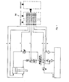
- FIG. 1 shows the circuit diagram of a fluid system with fluid lines as an application example of the invention.
- it is a leakage test device with a test cylinder and other elements to be monitored and tested.
- the fluid lines a, b, c, d, e, f and g are connected to the respective elements of the fluid system and all lead to a common collecting device 43, which consists of a socket and a connector, which will be described in the following is described in more detail.
- a group of connecting lines of the plug piece is directly connected integrally to a measuring device, while another group of fluid connecting lines or electrical conductors is led from the measuring device to a remote measuring, control or regulating device.
- the collecting device with the multiple quick coupling and the integrated measuring device enables all the variations mentioned.
- Any system that is equipped with a hydraulic system can be considered as a fluid system. It can be mobile or stationary systems.
- the mobile systems include earth moving systems such as excavators, ramming devices, as well as transport vehicles on wheels or chains, lifting vehicles or the like.
- the fluidic agent can also be present in various substances, i.e. one or a group of lines can carry a hydraulic oil, while compressed air is contained in one or a group of lines.
- the multiple quick coupling which is part of the collecting device 43, can simultaneously have high pressures of several hundred bar or lower and / or alternating pressures.
- FIG. 2 shows the multiple quick coupling which can be operated under operating pressure and which is designed with a socket and a plug piece 2 or 1.
- the further connector or socket piece 1 or 2 is connected to a measuring device 34 having a plurality of sensors.
- Corresponding connecting lines can also be led to further measuring, control and / or regulating devices, not shown in any more detail.
- the measuring device 34 has a housing 35 provided with a multiplicity of bores for receiving a pressure sensor 36 in each case.
- each bore is provided with a fluid channel 37 and a ventilation channel 38, at the end of which the ventilation screw 40 is located.
- the fluid channel 37 leads to a coupling socket 7 of the socket or plug piece 2 or 1.
- Each pressure sensor 36 forms with the housing 35 a sealed pressure sensor chamber 39 with a relatively small volume.
- the pressure sensor 36 which is designed in a manner known per se as a semiconductor element with an integrated amplifier circuit and possibly a temperature compensator and compensator circuit, has electrical connections which lead to a switching strip (not shown in detail) on the outside.
- the housing 35 which is provided with a plurality of bores, is at the same time designed as a plug 1 of the multiple quick coupling.
- the housing 35 can alternatively also be constructed as a piece of a can.
- FIG. 2 shows a plug piece 1 which is coupled to a socket piece 2.
- FIG. 3 shows an enlarged section X from FIG. 2. Reference is therefore made to FIG. 3 at the same time.
- the plug piece 1 has a housing 3 and in a corresponding manner the socket piece 2 also has a housing 4. Both housings 3 and 4 are provided with a plurality of axially parallel bores 5 and 6 for receiving a coupling socket 7 and 7 ⁇ with a radial clearance 8 and 8 ⁇ provided.
- the coupling sockets 7 ⁇ of the connector 1 are of the same design as the coupling sockets 7 of the socket piece 2, so that for the time being a description of a coupling socket 7 in the socket piece 2 is given.
- each coupling bush 7 there is a spring-loaded and mechanically actuable check valve 9 with a cylindrical valve body 10.
- the valve body 10 presses with the outer edge and / or end face of its sealing shoulder 11 in the closed valve state against a sealing ring 12 which is connected to the coupling bush 7 or one in the coupling bush 7 arranged sealing bush 13 forms a sealable flow channel 14.
- each mechanically actuated check valve 9 ⁇ of the connector piece 1 has a captive and provided with a through-bore 15 flying piston 16, the output nipple 17 for pushing open the cylindrical valve body 10 of its associated mechanically actuated Check valve 9 of the socket piece 2 and its input nipple 18 serves to push open the cylindrical valve body 10 ⁇ of the mechanically actuated check valve 9 ⁇ of the plug piece 1 and is designed accordingly.
- the flying piston 16 is provided with an outer stop collar 19 to limit its penetration depth into the mechanically actuated check valve 9 of the can piece 2 assigned to it.
- the flying piston has an inner stop collar 20 to limit the depth of penetration into the mechanically actuated check valve 9 'of the plug piece 1 arranged downstream of it.
- Each bore 5 in the housing of the connector 1 is provided on the output side with a backward rotation 21 to limit the axial movement of the flying piston 16.
- a further flow channel seal 22 or 22 ⁇ is arranged downstream and / or upstream of the sealing ring 12 or 12 ⁇ , which seals the cylindrical valve body 10 or 10 ⁇ through the input or output nipple 18 or 17 of the respective flying piston 16 during the coupling process, its sealing function is only delayed after the sealing ring 12 or 12 ⁇ has been lifted from the sealing shoulder 11 or 11 ⁇ .
- Each coupling bushing 7 is provided on its output side with a snap ring 23 which bears against a collar 24 of the corresponding hose nipple and is held by a one-part or multi-part perforated disk 25 braced by screw connections.
- the housing 35 is clamped to the perforated disk 41 with the aid of the bolts 26.
- the housing 4 of the socket piece 2 and its perforated disk 25 are provided with a central bore 42 in which the centering pin 28 is arranged for centering the perforated disk 25.
- the housing 3 of the connector 1 is provided with a central threaded bore 29, in which there is a clamping bolt 30 for bracing the housing 35 and which is provided with a threading and centering pin 31 extending from the housing of the connector 1.
- the centering pin 31 of the plug 1 extends into the bore 42 of the socket 2, whereby the threading process and the centering are ensured.
- centering pin 31 protrudes longer from the housing 3 of the connector 1 than the coding pins 32 described below, which serve the correct radial assignment.
- the front sides of the housings 3 and 4 of the socket piece and of the plug piece 1 and 2 have radially acting coding pins 32 which engage in defined coding holes 33 during the coupling process.
- the connector 1 is also provided with a rotatably mounted screw sleeve 27 with an internal thread and the outside of the housing 4 of the socket piece 2 is provided with a thread which engages in the aforementioned internal thread of the screw sleeve 27.
- the rotatably mounted screw sleeve 27 also has radially directed wings on its circumference for better handling.
- the upper end face or the outer edge of the sealing shoulder 10 or 10 ⁇ presses in the closed valve state against the sealing ring 12 or 12 ⁇ made of an elastomeric material.
- the valve body 10 or 10 ⁇ with an annular web of the sealing bush 13 or 13 ⁇ forms a seal in the form of a throttle section.
- valve body 10 If the valve body 10 is pushed open with the aid of the output nipple 17 of the flying piston 16, the sealing ring 12 lifts off the sealing shoulder 11 of the valve body 10, while the throttle section seal continues to maintain its sealing function until the ring web of the sealing bush 13 maintains the conical upper part of the valve body 10 leaves. In a corresponding manner, the input nipple 18 of the flying piston 16 acts on the valve body 10 ⁇ .
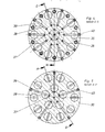
- FIGS. 4 and 5 with the sections C-D and E-F from FIG. 2 serve to further illustrate the invention.
Landscapes
- Engineering & Computer Science (AREA)
- General Engineering & Computer Science (AREA)
- Physics & Mathematics (AREA)
- General Physics & Mathematics (AREA)
- Mechanical Engineering (AREA)
- Measuring Fluid Pressure (AREA)
- Quick-Acting Or Multi-Walled Pipe Joints (AREA)
- Fluid-Driven Valves (AREA)
- Investigating Or Analysing Biological Materials (AREA)
Abstract
Description
- Die Erfindung betrifft ein Fluidisches System mit einer Meßvorrichtung, dessen Fluid Hochdrücke von mehreren hundert bar oder Unter- und/oder wechselnde Drücke aufweist, welches mit Meß-, Steuer- und/oder Regelleitungen versehen ist, die jeweils mit Meß, Steuer- und/oder Regelpunkten des Systems verbunden und zu einer Sammelvorrichtung zusammengeführt sind.
- Zur Erfassung von Arbeitsdrücken der fluidischen Medien ist beispielsweise eine Meßkupplung für fluidische Systeme bekannt, welche aus einer im eingebauten Zustand unter Leitungsdruck stehenden Kupplungsbuchse besteht, in deren Bohrung ein federbelastetes und mechanisch betätigbares Rückschlagventil angeordnet ist.
- Meßkupplungen dieser Art dienen zum Beispiel zur Herstellung von Prüf- oder Meßanschlüssen an Druckleitungen, wobei in der Regel die Kupplungsbuchse mit ihrem Einschraubgewinde fest an der Druckleitung eines fluidischen Systems installiert ist. Für die Dauer der Prüf- oder Meßarbeiten wird auf diese Kupplungsbuchse ein als Hohlzapfen ausgebildeter Dichtnippel mittels Überwurfmutter aufgeschraubt, der fest mit einem Schlauch verbunden ist. Die Kupplungen können beispielsweise unter Druck, d.h. ohne die Anlage stillzusetzen, über Meßschläuche mit den entsprechenden Meßgeräten verbunden werden. Bei Anschluß fest installierter Geräte, zum Beispiel Manometer, Manometer-Wahlschalter, elektrische Druckgeber und Druckschalter, können die flexiblen Meßschläuche wie Elektrokabel verlegt werden, so daß eine aufwendige Rohrverlegung entfällt. Mit solchen Meßkupplungen lassen sich daher die effektiven Arbeitsdrücke direkt in der Fluid - Leitung messen, wobei kein Lösen von Entlüftungsschrauben und Rohrverschraubungen erforderlich ist. Solche Kupplungen finden bei den verschiedensten Bauelementen und Regelungen von Fluid-Systemen Verwendung. Nach dem Trennen des Kupplungsanschlusses wird auf die Kupplungsbuchse mit Außengewinde eine Schutzkappe aufgeschraubt, die den Zweck hat, das Eindringen von Schmutz in die Kupplungsbuchse zu verhindern und welche darüberhinaus eine zusätzliche Abdichtfunktion übernimmt, für den Fall, daß ein in die Kupplungsbuchse installiertes Rückschlagventil nicht absolut dicht schließt.
- Ventilkupplungen der genannten Art gehen beispielsweise aus der DE-PS 27 56 084 hervor, wobei die Ventilkörper als Kegel oder Kugel ausgebildet sind. Bei dieser bekannten Ventilkupplung ist der Ventilkörper als Rückschlagventil auf einer Druckfeder federbeweglich angeordnet und weist an einem oberen Kontaktende einen Strömungskanal auf. Die Ventilkupplung ist dabei mit einem Dicht- und Verdrehsicherungsring versehen, dessen Dichtfunktion jedoch nur dann gewährleistet ist, wenn eine entsprechende Schlauch- oder Verschlußkappe mit ihrem Dichtnippel fest auf die Kupplungsbuchse aufgeschraubt ist.
- Sobald diese Kappe gelöst ist, bzw. falls eine solche Kappe überhaupt nicht vorhanden ist - wie zum Beispiel bei Manometerwahlschaltern -, erfolgt die Abdichtung des Druckmediums nur noch durch das entsprechende Rückschlagventil. Ein Rückschlagventil für solche Hochdruck-Ventilkupplungen zeigt jedoch konstruktionsbedingt je nach Viskosität des Druckmediums eine mehr oder weniger stark ausgeprägte Undichtheit bzw. ist unter Serienbedingungen jedenfalls nicht als praktisch dichte Ausführung darstellbar.
- Für Verschlauchungen in der allgemeinen Hydraulik und für Gasfülleinrichtungen von Hydraulikspeichern ist eine derartige Ausbildung ausreichend, doch ergeben sich schon dann Reklamationen wegen Undichtheit, wenn zum Beispiel bei mehreren Ventilkupplungen gleichzeitig die Kappen gelöst werden, um mit einer Meßeinrichtung nacheinander mehrere Meßstellen zu prüfen, wenn bei Hydraulikspeichern Gasdruck-Prüfeinrichtungen ohne Nachfüllmöglichkeit benutzt werden, oder wenn die Ventilkupplungen zur Überwachung von Anlagen mit brennbaren Gasen etc. eingesetzt sind.
- Zur Anwendung in Manometer-Wahlschaltern ist der Einsatz solcher Ventilkupplungen wegen ständiger Leckage an den jeweils nicht benutzten Anschlüssen überhaupt nicht möglich. Es ist bei den genannten Ventilkupplungen auch schon versucht worden, das Rückschlagventil mit gummielastischen Dichtungen bzw. üblichen O-Ringen auszustatten, jedoch konnte hierdurch trotz anfänglicher, genügender Dichtheit nicht in allen Fällen ein positives Ergebnis erzielt werden. Bei langen Meßleitungen und großen Totvolumina in Manometern oder in dem angeschlossenen Kreislauf und insbesondere bei niedrigviskosen Flüssigkeiten oder höheren Betriebsdrücken bzw. bei Prüfeinrichtungen für Hydrospeicher erfolgt ein Auswaschen der gummielastischen Dichtung, da eine hohe Druckdifferenz beim Abheben des Ventils eine sehr starke Strömung des verwendeten Mediums an der Dichtung bewirkt.
- Aus diesen Gründen wurde bereits eine Ventilkupplung, vorzugsweise eine Venil-Meßkupplung vorgeschlagen, welche für fluidische Systeme mit hohen Arbeitsdrücken und Medien unterschiedlichster Viskosität geeignet ist. Hierbei wurden Maßnahmen vorgeschlagen, die aus einem elastomeren Werkstoff bestehende Dichtung gegen Kavitation und Auswaschungen zu schützen und die Wirkung von großen Volumina in Meßleitungen oder dergleichen des angeschlossenen Kreislaufs auf die elastomere Dichtung auszuschalten, indem bei einer Ventilkupplung ein zylindrischer Ventilkörper, welcher mit der Außenkante und/oder Stirnfläche seiner Dichtschulter im geschlossenen Ventilzustand gegen eine aus elastomeren Werkstoff bestehenden Dichtring preßt, mit der Kupplungsbuchse bzw. einer in der Kupplungsbuchse angeordneten Dichtbuchse einen abdichtbaren Strömungskanal bildet, wobei stromabwärts und/oder stromaufwärts zum Dichtring weitere Dichtungen angeordnet sind, welche bei Aufstoßen des Ventilkörpers ihre Dichtfunktion erst nach dem Abheben des Dichtringes von der Dichtschulter vorzugsweise verzögert beenden. Durch diese Maßnahme wird sichergestellt, daß die aufgrund der hohen Druckdifferenz entstehende Strömung unmittelbar nach dem Ablösen des elastomeren Dichtringes von seiner Ventilschulter gedrosselt oder nahezu zum Stillstand gebracht wird.
- Die Abnahme der Dichtfunktion der stromabwärts und/oder stromaufwärts zum Dichtring angeordneten Dichtungen während des Aufstoßvorganges des Ventilkörpers verläuft im Vergleich zur Abnahme der Dichtfunktion des Dichtringes über einen längeren Hubweg. Auf diese Weise üben die stromabwärts und/oder stromaufwärts zum Dichtring angeordneten Dichtungen noch ihre Dichtfunktion aus, während aufgrund des kürzeren Hubweges des Dichtringes dieser der nachteiligen Wirkung einer sonst entstehenden Strömung und einer sich dadurch ausgebildeten Kavitation oder Auswaschung entzogen ist.
- Der Einsatz von Hydraulikanlagen im Verbund mit anderen Systemkomponenten und von elektrohydraulischen Elementen erfordert bei Ausfall oder mangelhafter Funktion ein möglichst schnelle und genaue Diagnose, so daß der Zustand bestimmter Baugruppen unmittelbar erkannt werden kann. Hierzu sind Druckmeßdaten möglichst vieler Komponenten des Systems in kurzer Zeit, vorzugsweise gleichzeitig erforderlich. Hierzu eignen sich die eingangs beschriebenen Meßkupplungen besonders. Diese werden an den strategisch wichtigen Meßpunkten einer Anlage verlegt und ggf. auf einer Blende mittels Meßleitungen zusammengefaßt. Werden nunmehr die Messungen durchgeführt, so müssen die Hochdruckschläuche einzeln mit den Monomeßpunkten verbunden werden. Verwechselungen der Anschlüsse beim Anschließen sind oftmals die Folge, so daß Falschmessungen durchgeführt werden. Darüberhinaus können aber auch angeschlossene Meßgeräte beschädigt oder zerstört werden, wenn die eingehenden Meßwerte nicht mit den Meßbereichen des Gerätes übereinstimmen.
- Es sind ferner Mehrfachkupplungen bekannt, welche sich jedoch nur bei geringen Systemdrücken von Hand betätigen lassen. Bei Systemen mit hohen Drücken läßt sich der Kupplungsvorgang nur maschinell durchführen oder das System muß vor dem Kupplungsvorgang drucklos geschaltet werden.
- Der Erfindung liegt die Aufgabe zugrunde ein fluidisches System in Kombination mit einer Meßvorrichtung anzugeben, bei dem Meß-, Steuer- und/oder Regelleitungen mit den entsprechenden Punkten des Systems fest installiert sind und zu einer Sammelvorrichtung führen, wobei die bereits vorgeschlagene Monokupplung verwendet und diese zu einer Vielfachkupplung entwickelt wird, um die erfaßten Drücke über eine Multileitung zu übertragen, so daß die Messungen - aufgenommen an den verschiedensten Punkten des Systems - an zentraler Stelle und - falls erforderlich - auch gleichzeitig durchgeführt werden können.
- Der Erfindung liegt weiter die Aufgabe zugrunde ein Meßsystem vorzuschlagen, bei dem eine Vielzahl von Sensoren, vorzugsweise Drucksensoren, mittels eines einzigen Kuppelvorganges mit den entsprechend zugeordneten Meßstellen oder Meßpunkten des Systems verbunden werden.
- Die Lösung dieser Aufgabe erfolgt dadurch, daß nach der Erfindung die Sammelvorrichtung als eine unter Betriebsdruck betätigbare Mehrfachschnellkupplung mit einem Dosen- und einem Steckerstück ausgebildet ist, und daß das weiterführende Stecker- oder Dosenstück mit einer eine Vielzahl von Sensoren aufweisenden Meßvorrichtung und/oder mit Steuer- und/oder Regelvorrichtungen verbunden ist.
- In Weiterbildung der Erfindung weist die Meßvorrichtung ein mit einer Vielzahl von Bohrungen versehenes Gehäuse zur Aufnahme jeweils eines Drucksensorgehäuses auf, wobei jede Bohrung mit einem Fluid-Kanal und einem Entlüftungskanal verbunden ist und der Fluid-Kanal zu einer Kupplungsbuchse des Dosen- oder Steckerstückes führt.
- Nach der Erfindung bildet jeder Drucksensor mit dem Gehäuse eine abgedichtete Drucksensorkammer kleinen Volumens.
- Die Drucksensorkammer weist in vorteilhafter Weise eine Entlüftungsvorrichtung auf, welche eine Entlüftungsschraube besitzt, die am Ausgang ihres Entlüftungskanals angeordnet ist, welche mit der Drucksensorkammer des Drucksensors fluidisch in Verbindung steht.
- Der Drucksensor weist ferner elektrische Anschlüße auf, die nach außen zu einer Schaltleiste führen.
- Die Lösung der weiteren Aufgabe erfolgt mit Hilfe einer Mehrfachschnellkupplung dadurch, daß nach der Erfindung sowohl das Stecker- als auch das Dosenstück ein Gehäuse mit mehreren achsparallelen Bohrungen zur Aufnahme jeweils einer Kupplungsbuchse mit Radialspiel aufweisen und in jeder Kupplungsbuchse ein federbelastetes und mechanisch betätigbares Rückschlagventil mit einem zylindrischen Ventilkörper angeordnet ist, welcher mit der Außenkante und/oder Stirnfläche seiner Dichtschulter im geschlossenen Ventilzustand gegen einen Dichtring preßt, der mit der Kupplungsbuchse bzw. einer in der Kupplungsbuchse angeordneten Dichtbuchse einen abdichtbaren Strömungskanal bildet, und jedes Rückschlagventil des Steckerstückes einen gefesselten und mit einer Durchbohrung versehenen fliegenden Kolben aufweist, dessen Ausgangsnippel zum Aufstoßen des zylindrischen Ventilkörpers des ihm zugeordneten mechanisch betätigbaren Rückschlagventils des Dosenstückes und dessen Eingangsnippel zum Aufstoßen des Ventilkörpers seines Rückschlagventils des Steckerstückes ausgebildet ist.
- In Weiterbildung der Erfindung weist der fliegende Kolben einen äußeren Anschlagbund zur Begrenzung seiner Eindringtiefe in das ihm zugeordnete Ventil des Dosenstückes und einen inneren Anschlagbund zur Begrenzung der Eindringtiefe in das ihm nachgeordnete Ventil auf, wobei jede Bohrung im Gehäuse des Steckerstückes ausgangsseitig mit einer Hinterdrehung zur Begrenzung der Achsialbewegung des fliegenden Kolbens versehen ist.
- In jedem Rückschlagventil des Dosen- und des Steckerstückes sind stromabwärts und/oder stromaufwärts zum aus elastomerem Werkstoff bestehenden Dichtring weitere Strömungskanal-Dichtungen angeordnet, welche beim Aufstoßen des Ventilkörpers durch den Eingangs- oder Ausgangsnippel des jeweiligen fliegenden Kolbens beim Kuppelvorgang ihre Dichtfunktion erst nach dem Abheben des Dichtringes von der Dichtschulter vorzugsweise verzögert beenden.
- In vorteilhafter Weise weist jede Kupplungsbuchse an ihrer Ausgangsseite einen Sprengring auf, welcher gegen einen Bund eines Schlauchnippels anliegt und von einer ein- oder mehrteiligen, durch Verschraubungen verspannten Lochscheibe gehalten ist.
- Das Gehäuse des Dosenstückes und ihre Lochscheibe weisen eine zentrale Bohrung auf, in der ein Zentrierstift zur Zentrierung der Lochscheibe angeordnet ist.
- Die Lochscheibe des Steckerstückes weist eine zentrale Gewindebohrung auf, in der sich ein Spannbolzen zur Verspannung der Lochscheibe befindet und welcher mit einem aus dem Gehäuse des Steckerstückes reichenden Einfädel- und Zentrierstift versehen ist.
- Die Frontseiten der Gehäuse des Dosen- und des Steckerstückes weisen radial wirkende Kodierstifte auf, welche beim Kuppelvorgang in definierte Kodierbohrungen eingreifen.
- In vorteilhafter Weise ragt der Zentrierstift länger als die Kodierstifte aus dem Gehäuse des Steckerstückes.
- Die Erfindung wird anhand der Figuren näher erläutert. Hierbei zeigen:
- FIGUR 1 das Schaltbild einer Fluid-Anlage mit Fluid-Leitungen, zusammengeführt zu einer Sammelvorrichtung mit einer Meßvorrichtung;
- FIGUR 2 einen Längsschnitt durch ein Steckerstück mit integral verbundener Meßvorrichtung und ein mit dem Steckerstück gekuppeltes Dosenstück;
- FIGUR 3 eine vergrößerte Darstellung eines in der Figur 1 mit X bezeichneten Ausschnittes,
- FIGUR 4 einen Schnitt C-D nach Figur 2, und
- FIGUR 5 einen Schnitt E-F nach Figur 2 .
- In den verschiedenen Zeichnungen bzw. Abbildungen sind gleiche Elemente mit gleichen Bezugszeichen versehen, während gleichartige Elemente mit gleicher Bezifferung und mit Indizes bezeichnet sind.
- In der Figur 1 ist das Schaltbild einer Fluid-Anlage mit Fluid-Leitungen als ein Anwendungsbeispiel der Erfindung dargestellt. In diesem Falle handelt es sich um eine Leckageprüfeinrichtung mit Prüfzylinder und weiteren zu überwachenden und zu prüfenden Elementen. Die Fluid-Leitungen a, b, c, d, e, f und g sind mit den jeweiligen Elementen der Fluid-Anlage verbunden und führen sämtlich zu einer gemeinsamen Sammelvorrichtung 43, welche aus einem Dosen- und einem Steckerstück besteht, welches im folgenden noch näher beschrieben wird. Eine Gruppe von Verbindungsleitungen des Steckerstückes ist direkt mit einer Meßvorrichtung intergral verbunden, während eine andere Gruppe von Fluidverbindungsleitungen oder elektrischen Leitern aus der Meßvorrichtung zu einem entfernt gelegenen Meß-, Steuer- oder Regelgerät geführt ist. Die Sammelvorrichtung mit der Mehrfachschnellkupplung und dem integrierten Meßgerät ermöglicht alle angesprochenen Variationen. Als Fluid-Anlage kommt jede Anlage infrage, welche beispielsweise mit einer Hydraulik ausgerüstet ist. Es können mobile oder stationäre Anlagen sein. Zu den mobilen Anlagen zählen Erdbewegungsanlagen wie Bagger, Rammvorrichtungen, ferner Transportfahrzeuge auf Rädern oder Ketten, Hebefahrzeuge oder dergleichen.
- Das fluidische Mittel kann auch in verschiedenen Stoffen vorliegen, d.h. eine oder eine Gruppe von Leitungen kann ein Hydrauliköl führen, während in einer oder einer Gruppe von Leitungen Preßluft enthalten ist. Die Mehrfachschnellkupplung, welche Bestandteil der Sammelvorrichtung 43 ist, kann gleichzeitig Hochdrücke von mehreren hundert bar oder Unter- und/oder wechselnde Drücke aufweisen.
- Die Figur 2 zeigt die unter Betriebsdruck betätigbare Mehrfachschnellkupplung, welche mit einem Dosen- und einem Steckerstück 2 bzw.1 ausgebildet ist. Das weiterführende Stecker- oder Dosenstück 1 bzw. 2 ist mit einer eine Vielzahl von Sensoren aufweisenden Meßvorrichtung 34 verbunden. Entsprechende Verbindungsleitungen können auch zu nicht näher dargestellten weiteren Meß-, Steuer- und/oder Regelvorrichtungen geführt sein.
- Die Meßvorrichtung 34 weist ein mit einer Vielzahl von Bohrungen versehenes Gehäuse 35 zur Aufnahme jeweils eines Drucksensors 36 auf. Zur Herstellung der Fluidverbindung ist jede Bohrung mit einem Fluid-Kanal 37 und einem Entlüftungskanal 38 versehen, an dessen Ende sich die Entlüftungsschraube 40 befindet. Der Fluid-Kanal 37 führt zu einer Kupplungsbuchse 7 des Dosen- oder Steckerstückes 2 bzw. 1. Jeder Drucksensor 36 bildet mit dem Gehäuse 35 eine abgedichtete Drucksensorkammer 39 mit einem relativ kleinen Volumen.
- Der Drucksensor 36, welcher in an sich bekannter Weise als Halbleiterelement mit integrierter Verstärkerschaltung und gegebenenfalls Temperaturkompensator und Kompensatorschaltung ausgebildet ist, weist elektrische Anschlüße auf, die außen zu einer nicht näher dargestellten Schaltleiste führen.
- Das mit einer Vielzahl von Bohrungen versehene Gehäuse 35 ist gleichzeitig als Steckerstück 1 der Mehrfachschnellkupplung ausgebildet. Das Gehäuse 35 kann jedoch alternativ auch als Dosenstück aufgebaut sein.
- Die Figur 2 zeigt ein Steckerstück 1, welches mit einem Dosenstück 2 gekoppelt ist. Die Figur 3 zeigt einen vergrößerten Ausschnitt X aus Figur 2. Es wird daher gleichzeitig auf die Figur 3 verwiesen.
- Das Steckerstück 1 weist ein Gehäuse 3 auf und in entsprechender Weise besitzt auch das Dosenstück 2 ein Gehäuse 4. Beide Gehäuse 3 und 4 sind mit mehreren achsparallelen Bohrungen 5 bzw. 6 zur Aufnahme jeweils einer Kupplungsbuchse 7 bzw. 7ʹ mit einem Radialspiel 8 bzw. 8ʹ versehen. Die Kupplungsbuchsen 7ʹ des Steckerstückes 1 sind gleichartig zu den Kupplungsbuchsen 7 des Dosenstückes 2 ausgebildet, so daß vorerst die Beschreibung einer Kupplungsbuchse 7 in dem Dosenstück 2 erfolgt.
- In jeder Kupplungsbuchse 7 befindet sich ein federbelastetes und mechanisch betätigbares Rückschlagventil 9 mit einem zylindrischen Ventilkörper 10. Der Ventilkörper 10 preßt mit der Außenkante und/oder Stirnfläche seiner Dichtschulter 11 im geschlossenen Ventilzustand gegen einen Dichtring 12, der mit der Kupplungsbuchse 7 bzw. einer in der Kupplungsbuchse 7 angeordneten Dichtbuchse 13 einen abdichtbaren Strömungskanal 14 bildet.
- Die gleichen Elemente befinden sich in den Kupplungsbuchsen 7ʹ der Steckerstücke 1. Jedes mechanisch betätigbare Rückschlagventil 9ʹ des Steckerstückes 1 weist jedoch einen gefesselten und mit einer Durchbohrung 15 versehenen fliegenden Kolben 16 auf, dessen Ausgangsnippel 17 zum Aufstoßen des zylindrischen Ventilkörpers 10 des ihm zugeordneten mechanisch betätigbaren Rückschlagventils 9 des Dosenstückes 2 und dessen Eingangsnippel 18 zum Aufstoßen des zylindrischen Ventilkörpers 10ʹ des mechanisch betätigbaren Rückschlagventils 9ʹ des Steckerstückes 1 dient und dementsprechend ausgebildet ist.
- Der fliegende Kolben 16 ist mit einem äußeren Anschlagbund 19 zur Begrenzung seiner Eindringtiefe in das ihm zugeordnete mechanisch betätigbare Rückschlagventil 9 des Dosenstückes 2 versehen.
- Ferner weist der fliegende Kolben einen inneren Anschlagbund 20 zur Begrenzung der Eindringtiefe in das ihm nachgeordnete mechanisch betätigbare Rückschlagventil 9ʹ des Steckerstückes 1 auf. Jede Bohrung 5 im Gehäuse des Steckerstückes 1 ist ausgangsseitig mit einer Hinterdrehung 21 zur Begrenzung der Axialbewegung des fliegenden Kolbens 16 versehen.
- In jedem mechanisch betätigbaren Rückschlagventil 9 bzw. 9ʹ des Dosen- und des Steckerstückes 2 bzw. 1 ist stromabwärts und/oder stromaufwärts zum Dichtring 12 bzw. 12ʹ eine weitere Strömungskanal-Dichtung 22 bzw. 22ʹ angeordnet, welche beim Aufstoßen des zylindrischen Ventilkörpers 10 bzw. 10ʹ durch den Eingangs- oder Ausgangsnippel 18 bzw. 17 des jeweiligen fliegenden Kolbens 16 beim Kuppelvorgang ihre Dichtfunktion erst nach dem Abheben des Dichtringes 12 bzw. 12ʹ von der Dichtschulter 11 bzw. 11ʹ verzögert beendet.
- Jede Kupplungsbuchse 7 ist an ihrer Ausgangsseite mit einem Sprengring 23 versehen, welcher gegen einen Bund 24 des entsprechenden Schlauchnippels anliegt und von einer ein- oder mehrteiligen, durch Verschraubungen verspannten Lochscheibe 25 gehalten ist. In entsprechener Weise ist das Gehäuse 35 mit der Lochscheibe 41 mit Hilfe der Bolzen 26 verspannt.
- Das Gehäuse 4 des Dosenstückes 2 und seine Lochscheibe 25 sind mit einer zentralen Bohrung 42 versehen, in der der Zentrierstift 28 zur Zentrierung der Lochscheibe 25 angeordnet ist.
- Das Gehäuse 3 des Steckerstückes 1 ist mit einer zentralen Gewindebohrung 29 versehen, in der sich ein Spannbolzen 30 zur Verspannung des Gehäuses 35 befindet und welcher mit einem aus dem Gehäuse des Steckerstückes 1 reichenden Einfädel- und Zentrierstift 31 versehen ist. Im gekoppelten Zustand erstreckt sich der Zentrierstift 31 des Steckerstückes 1 in die Bohrung 42 des Dosenstückes 2, wodurch der Einfädelvorgang und die Zentrierung gesichert sind.
- Um dies zu erreichen, ragt der Zentrierstift 31 länger aus dem Gehäuse 3 des Steckerstückes 1 als die im folgenden beschriebenen Kodierstifte 32, welche der richtigen radialen Zuordnung dienen.
- Zur Sicherstellung der radialen Zuordnung des Steckerstückes zum Dosenstück weisen die Frontseiten der Gehäuse 3 und 4 des Dosen- und des Steckerstückes 1 und 2 radial wirkende Kodierstifte 32 auf, welche beim Kuppelvorgang in definierte Kodierbohrungen 33 eingreifen.
- Das Steckerstück 1 ist ferner mit einer drehbar gelagerten Verschraubungshülse 27 mit Innengewinde versehen und die Außenseite des Gehäuses 4 des Dosenstückes 2 ist mit einem in das genannte Innengewinde der Verschraubungshülse 27 greifenden Gewinde versehen.
- Die drehbar gelagerte Verschraubungshülse 27 weist ferner an ihrem Umfang radial gerichtete Flügel zur besseren Handhabung auf.
- Wie aus der Figur 3 hervorgeht, preßt die obere Stirnfläche bzw. die Außenkante der Dichtschulter 10 bzw. 10ʹ im geschlossenen Ventilzustand gegen den aus einem elastomeren Werkstoff bestehenden Dichtring 12 bzw. 12ʹ. Stromabwärts zum Dichtring 12 bzw. 12ʹ bildet der Ventilkörper 10 bzw. 10ʹ mit einem Ringsteg der Dichtbuchse 13 bzw. 13ʹ eine in Form einer Drosselstrecke ausgebildete Dichtung.
- Wird der Ventilkörper 10 mit Hilfe des Ausgangsnippels 17 des fliegenden Kolbens 16 aufgestoßen, so hebt der Dichtring 12 von der Dichtschulter 11 des Ventilkörpers 10 ab, während die als Drosselstrecke ausgebildete Dichtung ihre Dichtfunktion weiterhin aufrechterhält, bis der Ringsteg der Dichtbuchse 13 den kegelförmigen oberen Teil des Ventilkörpers 10 verläßt. In entsprechender Weise wirkt der Eingangsnippel 18 des fliegenden Kolbens 16 auf den Ventilkörper 10ʹ ein.
- Die Vermeidung einer Strömung oder Reduzierung der Geschwindigkeit des an der Strömungskanaldichtung 22 vorbeiströmenden Mediums bewirkt, daß eine Auswaschung oder Kavitation dieser Dichtung verhindert wird. Damit wird erreicht, daß das gesamte Dichtungssystem bei äußerst hohen Drücken und auch für Gase anwendbar ist, wobei durch die Zuordnung und Ausbildung der verschiedenen Dichtungen eine äußerst lange Lebensdauer sichergestellt wird.
- Zur weiteren Veranschaulichung der Erfindung dienen die Schnittzeichnungen nach den Figuren 4 und 5 mit den Schnitten C-D und E-F aus Figur 2.
- Mit der Erfindung ist nunmehr die Möglichkeit gegeben, eine Vielzahl von Meß-, Steuer- oder Regelleitungen eines fluidischen Systems über eine mit einer Steckkupplung versehene Gruppe von Leitungen einer integral mit der Steckkupplung verbundenen Druckmeßvorrichtung oder bzw. und einer sich anschließenden weiteren Meß-, Steuer- oder Regelvorrichtung zuzuführen, um dort die aufgenommenen Meß- oder Steuerwerte zentral verarbeiten zu können. Mit einem einzigen von Hand ausführbaren Kuppelvorrgang können mit der Erfindung alle Fluid-Meßstellen des Systems in richtiger Zuordnung mit ihren Meßgeräten gleichzeitig und unter dem herrschenden Betriebsdruck verbunden werden. Das System muß daher für die Messung bzw. für den Anschluß der Meßgeräte nicht abgeschaltet werden, sondern die Messung kann unmittelbar nach dem Kuppelvorgang der Mehrfachschnellkupplung erfolgen. Eine Verwechselung eines Anschlusses mit einem zugeordneten Meß- oder Steuergerät ist ausgeschlossen, so daß keine Fehlmessungen oder sogar Zerstörungen der Geräte auftreten können.
Claims (14)
Priority Applications (6)
| Application Number | Priority Date | Filing Date | Title |
|---|---|---|---|
| EP19860101980 EP0233302B1 (de) | 1986-02-17 | 1986-02-17 | Fluidisches System mit Messvorrichtung |
| DE8686101980T DE3673386D1 (de) | 1986-02-17 | 1986-02-17 | Fluidisches system mit messvorrichtung. |
| AT86101980T ATE55467T1 (de) | 1986-02-17 | 1986-02-17 | Fluidisches system mit messvorrichtung. |
| DE19863605381 DE3605381A1 (de) | 1986-02-17 | 1986-02-20 | Fluidisches system mit messvorrichtung |
| JP3261587A JPH0612306B2 (ja) | 1986-02-17 | 1987-02-17 | 計測装置を有する流体系統 |
| US07/015,653 US4770207A (en) | 1986-02-17 | 1987-02-17 | Fluidic system |
Applications Claiming Priority (1)
| Application Number | Priority Date | Filing Date | Title |
|---|---|---|---|
| EP19860101980 EP0233302B1 (de) | 1986-02-17 | 1986-02-17 | Fluidisches System mit Messvorrichtung |
Publications (2)
| Publication Number | Publication Date |
|---|---|
| EP0233302A1 true EP0233302A1 (de) | 1987-08-26 |
| EP0233302B1 EP0233302B1 (de) | 1990-08-08 |
Family
ID=8194901
Family Applications (1)
| Application Number | Title | Priority Date | Filing Date |
|---|---|---|---|
| EP19860101980 Expired - Lifetime EP0233302B1 (de) | 1986-02-17 | 1986-02-17 | Fluidisches System mit Messvorrichtung |
Country Status (5)
| Country | Link |
|---|---|
| US (1) | US4770207A (de) |
| EP (1) | EP0233302B1 (de) |
| JP (1) | JPH0612306B2 (de) |
| AT (1) | ATE55467T1 (de) |
| DE (2) | DE3673386D1 (de) |
Cited By (4)
| Publication number | Priority date | Publication date | Assignee | Title |
|---|---|---|---|---|
| DE3638604A1 (de) * | 1986-11-12 | 1988-05-26 | Hydrotechnik Gmbh | Fluidisches system mit volumenstrommesseinrichtung |
| EP0285082A3 (de) * | 1987-04-01 | 1991-03-13 | Hydrotechnik GmbH | Vorrichtung zur Prüfung der Komponenten eines hydraulischen Hochdrucksystems |
| US5994601A (en) * | 1996-07-24 | 1999-11-30 | Huels Aktiengesellschaft | Process for preparing butene oligomers from Fischer-Tropsch olefins |
| EP2241864B1 (de) * | 2009-04-14 | 2018-08-08 | Hydrotechnik GmbH | Vorrichtung zur Messung des Volumens- oder Messestromes eines Mediums mittels Differenzdrucksensors mit einer Verbindungsvorrichtung für den Sensor |
Families Citing this family (14)
| Publication number | Priority date | Publication date | Assignee | Title |
|---|---|---|---|---|
| FR2636716B1 (fr) * | 1988-09-21 | 1990-12-07 | Staubli Sa Ets | Dispositif pour l'accouplement des platines porte-elements des raccords multiples |
| GB2279418A (en) * | 1993-06-23 | 1995-01-04 | Scotech Limited | Flanged pipe component with valve in the flange |
| US5833278A (en) * | 1997-06-18 | 1998-11-10 | Rianda; Kent A. | Multiple line compression fitting assembly |
| EP1016573B1 (de) * | 1998-12-28 | 2006-11-02 | Kelsey-Hayes Company | Pressure sensor for a hydraulic control system and method for installing the sensor |
| DE19916087A1 (de) | 1999-04-09 | 2000-10-26 | Lucas Ind Plc | Anordnung zur Messung eines Fluiddrucks |
| US6591684B2 (en) | 1998-12-28 | 2003-07-15 | Kelsey-Hayes Company | Pressure sensor intergrated into an electro-hydraulic control unit |
| US6032691A (en) * | 1999-03-29 | 2000-03-07 | Kaylynn, Inc. | Valve assembly |
| DE10044144B4 (de) * | 2000-09-06 | 2006-04-13 | Klenk Gmbh | Anschlussvorrichtung zum Verbinden einer Fluidleitung mit einer zweiten Anschlussvorrichtung |
| US20080254415A1 (en) * | 2005-09-16 | 2008-10-16 | Barry J Keith | System and Method for Training an Excavator Operator |
| DE102006001425B4 (de) * | 2006-01-10 | 2009-10-01 | Benteler Automobiltechnik Gmbh | Rohrprüfanlage |
| US8424920B2 (en) * | 2008-03-07 | 2013-04-23 | The Gates Corporation | Multi-port fluid connectors, systems and methods |
| CH700689A1 (de) * | 2009-03-16 | 2010-09-30 | Kistler Holding Ag | Multisensorkopf. |
| IT201800004494A1 (it) * | 2018-04-13 | 2018-07-13 | Sistema di prelievo e controllo pressione di esercizio per attrezzatura da demolizione | |
| WO2021069218A1 (de) * | 2019-10-10 | 2021-04-15 | Endress+Hauser SE+Co. KG | Druckmessgerät zur messung eines druckes |
Citations (2)
| Publication number | Priority date | Publication date | Assignee | Title |
|---|---|---|---|---|
| DE2537407A1 (de) * | 1975-08-22 | 1977-03-03 | Agfa Gevaert Ag | Schlauchkupplung |
| US4108008A (en) * | 1977-10-26 | 1978-08-22 | United Technologies Corporation | Quick connect multiple fluid/electrical transducer apparatus |
Family Cites Families (13)
| Publication number | Priority date | Publication date | Assignee | Title |
|---|---|---|---|---|
| DE1255417B (de) * | 1963-10-05 | 1967-11-30 | Daimler Benz Ag | Leicht loesbare Steckverbindung fuer Rohrleitungsbuendel |
| FR1436676A (fr) * | 1965-03-12 | 1966-04-29 | Commissariat Energie Atomique | Dispositif de détection de la variation d'une caractéristique d'un fluide |
| GB1387279A (en) * | 1972-05-05 | 1975-03-12 | Post Office | Fluid filled cable |
| SE391230B (sv) * | 1974-10-30 | 1977-02-07 | B F T Ekman | Ventilkopplingsanordning |
| US4103537A (en) * | 1976-09-07 | 1978-08-01 | Rice Hydro Equipment Manufacturing | Means and method of hydrostatic testing |
| DE2725575A1 (de) * | 1977-06-07 | 1978-12-21 | Karl Hehl | Vorrichtung zum abwechselnden anschliessen eines manometers an verschiedene druckmesstellen |
| DE2756084C3 (de) * | 1977-12-16 | 1980-06-26 | Hydrotechnik Gmbh, 6052 Muehlheim | Schraubsicherung |
| DE2922186C2 (de) * | 1979-05-31 | 1983-10-20 | Hydrotechnik Gmbh, 6250 Limburg | Steckkupplung für mehrere Schlauchverbindungen |
| EP0077612A1 (de) * | 1981-10-15 | 1983-04-27 | Plessey Overseas Limited | Verbindungsanordnung |
| US4441328A (en) * | 1981-12-08 | 1984-04-10 | Brister, Incorporated | Method and apparatus for forming a temporary plug in a submarine conduit |
| DE3328468A1 (de) * | 1982-08-10 | 1984-02-16 | Tectron (Eng) Ltd., Camberley, Surrey | Fluessigkeitsinjektor |
| US4480462A (en) * | 1982-10-25 | 1984-11-06 | Damco Testers, Inc. | Hydrostatic test apparatus |
| US4539998A (en) * | 1983-04-29 | 1985-09-10 | American Hospital Supply Corporation | Pressure transducer assembly |
-
1986
- 1986-02-17 DE DE8686101980T patent/DE3673386D1/de not_active Expired - Fee Related
- 1986-02-17 AT AT86101980T patent/ATE55467T1/de not_active IP Right Cessation
- 1986-02-17 EP EP19860101980 patent/EP0233302B1/de not_active Expired - Lifetime
- 1986-02-20 DE DE19863605381 patent/DE3605381A1/de active Granted
-
1987
- 1987-02-17 US US07/015,653 patent/US4770207A/en not_active Expired - Fee Related
- 1987-02-17 JP JP3261587A patent/JPH0612306B2/ja not_active Expired - Lifetime
Patent Citations (2)
| Publication number | Priority date | Publication date | Assignee | Title |
|---|---|---|---|---|
| DE2537407A1 (de) * | 1975-08-22 | 1977-03-03 | Agfa Gevaert Ag | Schlauchkupplung |
| US4108008A (en) * | 1977-10-26 | 1978-08-22 | United Technologies Corporation | Quick connect multiple fluid/electrical transducer apparatus |
Cited By (4)
| Publication number | Priority date | Publication date | Assignee | Title |
|---|---|---|---|---|
| DE3638604A1 (de) * | 1986-11-12 | 1988-05-26 | Hydrotechnik Gmbh | Fluidisches system mit volumenstrommesseinrichtung |
| EP0285082A3 (de) * | 1987-04-01 | 1991-03-13 | Hydrotechnik GmbH | Vorrichtung zur Prüfung der Komponenten eines hydraulischen Hochdrucksystems |
| US5994601A (en) * | 1996-07-24 | 1999-11-30 | Huels Aktiengesellschaft | Process for preparing butene oligomers from Fischer-Tropsch olefins |
| EP2241864B1 (de) * | 2009-04-14 | 2018-08-08 | Hydrotechnik GmbH | Vorrichtung zur Messung des Volumens- oder Messestromes eines Mediums mittels Differenzdrucksensors mit einer Verbindungsvorrichtung für den Sensor |
Also Published As
| Publication number | Publication date |
|---|---|
| EP0233302B1 (de) | 1990-08-08 |
| JPH0612306B2 (ja) | 1994-02-16 |
| JPS62254029A (ja) | 1987-11-05 |
| DE3605381C2 (de) | 1989-08-17 |
| US4770207A (en) | 1988-09-13 |
| DE3673386D1 (de) | 1990-09-13 |
| DE3605381A1 (de) | 1987-08-20 |
| ATE55467T1 (de) | 1990-08-15 |
Similar Documents
| Publication | Publication Date | Title |
|---|---|---|
| EP0233302B1 (de) | Fluidisches System mit Messvorrichtung | |
| EP0233301B1 (de) | Steckkupplung für mehrere Schlauchverbindungen | |
| EP0094439B1 (de) | Ventilkupplung für fluidische Systeme | |
| DE112019000578T5 (de) | Fluidleckage-erfassungsvorrichtung und hin und her bewegende fluiddruckvorrichtung | |
| DE102017206533A1 (de) | Quetschventil und Verfahren zum Betreiben eines Quetschventils | |
| EP0733822A1 (de) | Mit Fluid gefüllte Zylinder-Kolbenstangen-Einheit, insbesondere Gasfeder | |
| DE3218115C2 (de) | Ventilkupplung für fluidische Systeme | |
| DE2551126A1 (de) | Hydropneumatischer ventilantrieb | |
| DE3107012C2 (de) | ||
| DE4132690A1 (de) | Ventil- und messkupplung | |
| DE3926783C2 (de) | ||
| DE3435734A1 (de) | Einrichtung zur leckfeststellung | |
| DE102014221576A1 (de) | Druckzylinder zur hydraulischen Steuerung von Anbaugeräten an Arbeitsfahrzeugen und hydraulisches Steuerungssystem für Anbaugeräte an Arbeitsfahrzeugen mit derartigen Druckzylindern | |
| DE8327013U1 (de) | Messkupplung | |
| EP0519582B1 (de) | Gasdichte Rohrverbindung | |
| DE3015365A1 (de) | Einrichtung zum anpresen von dichtungen an absperrorganen | |
| DE3033739A1 (de) | Druckuebersetzer zur hoechstdruckerzeugung | |
| DE2553043A1 (de) | Kupplung zum herstellen eines anschlusses an ein unter druck stehendes system | |
| CH671287A5 (de) | ||
| DE102022128991B4 (de) | Ventil mit Entlüftungsfunktion | |
| DE3406271C2 (de) | ||
| DE8702770U1 (de) | Hydraulisches Wechselventil | |
| DD215635A1 (de) | Vorrichtung zur dichtheitspruefung von rohren | |
| DE102018120187A1 (de) | Adapter für eine hydraulische Strecke | |
| DE1450347B2 (de) | Zweiteiliger trennkolben zur gegenseitigen abdichtung benachbarter druckraeume eines zylinders eines kolbendruckspeichers |
Legal Events
| Date | Code | Title | Description |
|---|---|---|---|
| PUAI | Public reference made under article 153(3) epc to a published international application that has entered the european phase |
Free format text: ORIGINAL CODE: 0009012 |
|
| AK | Designated contracting states |
Kind code of ref document: A1 Designated state(s): AT BE CH DE FR GB IT LI NL SE |
|
| 17P | Request for examination filed |
Effective date: 19870829 |
|
| 17Q | First examination report despatched |
Effective date: 19880912 |
|
| GRAA | (expected) grant |
Free format text: ORIGINAL CODE: 0009210 |
|
| AK | Designated contracting states |
Kind code of ref document: B1 Designated state(s): AT BE CH DE FR GB IT LI NL SE |
|
| PG25 | Lapsed in a contracting state [announced via postgrant information from national office to epo] |
Ref country code: IT Free format text: LAPSE BECAUSE OF FAILURE TO SUBMIT A TRANSLATION OF THE DESCRIPTION OR TO PAY THE FEE WITHIN THE PRE;WARNING: LAPSES OF ITALIAN PATENTS WITH EFFECTIVE DATE BEFORE 2007 MAY HAVE OCCURRED AT ANY TIME BEFORE 2007. THE CORRECT EFFECTIVE DATE MAY BE DIFFERENT FROM THE ONE RECORDED.SCRIBED TIME-LIMIT Effective date: 19900808 Ref country code: FR Effective date: 19900808 Ref country code: NL Effective date: 19900808 |
|
| REF | Corresponds to: |
Ref document number: 55467 Country of ref document: AT Date of ref document: 19900815 Kind code of ref document: T |
|
| REF | Corresponds to: |
Ref document number: 3673386 Country of ref document: DE Date of ref document: 19900913 |
|
| GBT | Gb: translation of ep patent filed (gb section 77(6)(a)/1977) | ||
| EN | Fr: translation not filed | ||
| PGFP | Annual fee paid to national office [announced via postgrant information from national office to epo] |
Ref country code: CH Payment date: 19910111 Year of fee payment: 6 |
|
| NLV1 | Nl: lapsed or annulled due to failure to fulfill the requirements of art. 29p and 29m of the patents act | ||
| PG25 | Lapsed in a contracting state [announced via postgrant information from national office to epo] |
Ref country code: AT Effective date: 19910217 |
|
| PG25 | Lapsed in a contracting state [announced via postgrant information from national office to epo] |
Ref country code: BE Effective date: 19910228 |
|
| PGFP | Annual fee paid to national office [announced via postgrant information from national office to epo] |
Ref country code: DE Payment date: 19910424 Year of fee payment: 6 |
|
| PLBE | No opposition filed within time limit |
Free format text: ORIGINAL CODE: 0009261 |
|
| STAA | Information on the status of an ep patent application or granted ep patent |
Free format text: STATUS: NO OPPOSITION FILED WITHIN TIME LIMIT |
|
| 26N | No opposition filed | ||
| PG25 | Lapsed in a contracting state [announced via postgrant information from national office to epo] |
Ref country code: LI Effective date: 19920229 Ref country code: CH Effective date: 19920229 |
|
| REG | Reference to a national code |
Ref country code: CH Ref legal event code: PL |
|
| PG25 | Lapsed in a contracting state [announced via postgrant information from national office to epo] |
Ref country code: DE Effective date: 19921103 |
|
| PGFP | Annual fee paid to national office [announced via postgrant information from national office to epo] |
Ref country code: GB Payment date: 19930216 Year of fee payment: 8 Ref country code: SE Payment date: 19930216 Year of fee payment: 8 |
|
| PG25 | Lapsed in a contracting state [announced via postgrant information from national office to epo] |
Ref country code: GB Effective date: 19940217 |
|
| PG25 | Lapsed in a contracting state [announced via postgrant information from national office to epo] |
Ref country code: SE Effective date: 19940218 |
|
| GBPC | Gb: european patent ceased through non-payment of renewal fee |
Effective date: 19940217 |
|
| EUG | Se: european patent has lapsed |
Ref document number: 86101980.0 Effective date: 19940910 |