EP0232803B1 - Getriebe zur Überführung einer rotatorischen in eine translatorische Bewegung - Google Patents
Getriebe zur Überführung einer rotatorischen in eine translatorische Bewegung Download PDFInfo
- Publication number
- EP0232803B1 EP0232803B1 EP87101212A EP87101212A EP0232803B1 EP 0232803 B1 EP0232803 B1 EP 0232803B1 EP 87101212 A EP87101212 A EP 87101212A EP 87101212 A EP87101212 A EP 87101212A EP 0232803 B1 EP0232803 B1 EP 0232803B1
- Authority
- EP
- European Patent Office
- Prior art keywords
- guide
- strips
- gear according
- gear
- connecting member
- Prior art date
- Legal status (The legal status is an assumption and is not a legal conclusion. Google has not performed a legal analysis and makes no representation as to the accuracy of the status listed.)
- Expired
Links
Images
Classifications
-
- E—FIXED CONSTRUCTIONS
- E05—LOCKS; KEYS; WINDOW OR DOOR FITTINGS; SAFES
- E05F—DEVICES FOR MOVING WINGS INTO OPEN OR CLOSED POSITION; CHECKS FOR WINGS; WING FITTINGS NOT OTHERWISE PROVIDED FOR, CONCERNED WITH THE FUNCTIONING OF THE WING
- E05F15/00—Power-operated mechanisms for wings
- E05F15/60—Power-operated mechanisms for wings using electrical actuators
- E05F15/603—Power-operated mechanisms for wings using electrical actuators using rotary electromotors
- E05F15/665—Power-operated mechanisms for wings using electrical actuators using rotary electromotors for vertically-sliding wings
- E05F15/668—Power-operated mechanisms for wings using electrical actuators using rotary electromotors for vertically-sliding wings for overhead wings
- E05F15/67—Power-operated mechanisms for wings using electrical actuators using rotary electromotors for vertically-sliding wings for overhead wings operated by flexible or rigid rack-and-pinion arrangements
-
- B—PERFORMING OPERATIONS; TRANSPORTING
- B66—HOISTING; LIFTING; HAULING
- B66F—HOISTING, LIFTING, HAULING OR PUSHING, NOT OTHERWISE PROVIDED FOR, e.g. DEVICES WHICH APPLY A LIFTING OR PUSHING FORCE DIRECTLY TO THE SURFACE OF A LOAD
- B66F3/00—Devices, e.g. jacks, adapted for uninterrupted lifting of loads
- B66F3/02—Devices, e.g. jacks, adapted for uninterrupted lifting of loads with racks actuated by pinions
- B66F3/06—Devices, e.g. jacks, adapted for uninterrupted lifting of loads with racks actuated by pinions with racks comprising pivotable toothed sections or segments, e.g. arranged in pairs
-
- E—FIXED CONSTRUCTIONS
- E05—LOCKS; KEYS; WINDOW OR DOOR FITTINGS; SAFES
- E05F—DEVICES FOR MOVING WINGS INTO OPEN OR CLOSED POSITION; CHECKS FOR WINGS; WING FITTINGS NOT OTHERWISE PROVIDED FOR, CONCERNED WITH THE FUNCTIONING OF THE WING
- E05F15/00—Power-operated mechanisms for wings
- E05F15/60—Power-operated mechanisms for wings using electrical actuators
- E05F15/603—Power-operated mechanisms for wings using electrical actuators using rotary electromotors
- E05F15/665—Power-operated mechanisms for wings using electrical actuators using rotary electromotors for vertically-sliding wings
- E05F15/668—Power-operated mechanisms for wings using electrical actuators using rotary electromotors for vertically-sliding wings for overhead wings
- E05F15/673—Power-operated mechanisms for wings using electrical actuators using rotary electromotors for vertically-sliding wings for overhead wings operated by screw-and-nut mechanisms
-
- F—MECHANICAL ENGINEERING; LIGHTING; HEATING; WEAPONS; BLASTING
- F16—ENGINEERING ELEMENTS AND UNITS; GENERAL MEASURES FOR PRODUCING AND MAINTAINING EFFECTIVE FUNCTIONING OF MACHINES OR INSTALLATIONS; THERMAL INSULATION IN GENERAL
- F16G—BELTS, CABLES, OR ROPES, PREDOMINANTLY USED FOR DRIVING PURPOSES; CHAINS; FITTINGS PREDOMINANTLY USED THEREFOR
- F16G13/00—Chains
- F16G13/18—Chains having special overall characteristics
- F16G13/20—Chains having special overall characteristics stiff; Push-pull chains
-
- F—MECHANICAL ENGINEERING; LIGHTING; HEATING; WEAPONS; BLASTING
- F16—ENGINEERING ELEMENTS AND UNITS; GENERAL MEASURES FOR PRODUCING AND MAINTAINING EFFECTIVE FUNCTIONING OF MACHINES OR INSTALLATIONS; THERMAL INSULATION IN GENERAL
- F16H—GEARING
- F16H19/00—Gearings comprising essentially only toothed gears or friction members and not capable of conveying indefinitely-continuing rotary motion
- F16H19/02—Gearings comprising essentially only toothed gears or friction members and not capable of conveying indefinitely-continuing rotary motion for interconverting rotary or oscillating motion and reciprocating motion
- F16H19/06—Gearings comprising essentially only toothed gears or friction members and not capable of conveying indefinitely-continuing rotary motion for interconverting rotary or oscillating motion and reciprocating motion comprising flexible members, e.g. an endless flexible member
- F16H19/0636—Gearings comprising essentially only toothed gears or friction members and not capable of conveying indefinitely-continuing rotary motion for interconverting rotary or oscillating motion and reciprocating motion comprising flexible members, e.g. an endless flexible member the flexible member being a non-buckling chain
-
- E—FIXED CONSTRUCTIONS
- E05—LOCKS; KEYS; WINDOW OR DOOR FITTINGS; SAFES
- E05F—DEVICES FOR MOVING WINGS INTO OPEN OR CLOSED POSITION; CHECKS FOR WINGS; WING FITTINGS NOT OTHERWISE PROVIDED FOR, CONCERNED WITH THE FUNCTIONING OF THE WING
- E05F15/00—Power-operated mechanisms for wings
- E05F15/60—Power-operated mechanisms for wings using electrical actuators
- E05F15/603—Power-operated mechanisms for wings using electrical actuators using rotary electromotors
- E05F15/665—Power-operated mechanisms for wings using electrical actuators using rotary electromotors for vertically-sliding wings
- E05F15/668—Power-operated mechanisms for wings using electrical actuators using rotary electromotors for vertically-sliding wings for overhead wings
- E05F15/681—Power-operated mechanisms for wings using electrical actuators using rotary electromotors for vertically-sliding wings for overhead wings operated by flexible elongated pulling elements, e.g. belts
- E05F15/684—Power-operated mechanisms for wings using electrical actuators using rotary electromotors for vertically-sliding wings for overhead wings operated by flexible elongated pulling elements, e.g. belts by chains
-
- E—FIXED CONSTRUCTIONS
- E05—LOCKS; KEYS; WINDOW OR DOOR FITTINGS; SAFES
- E05Y—INDEXING SCHEME ASSOCIATED WITH SUBCLASSES E05D AND E05F, RELATING TO CONSTRUCTION ELEMENTS, ELECTRIC CONTROL, POWER SUPPLY, POWER SIGNAL OR TRANSMISSION, USER INTERFACES, MOUNTING OR COUPLING, DETAILS, ACCESSORIES, AUXILIARY OPERATIONS NOT OTHERWISE PROVIDED FOR, APPLICATION THEREOF
- E05Y2201/00—Constructional elements; Accessories therefor
- E05Y2201/40—Motors; Magnets; Springs; Weights; Accessories therefor
- E05Y2201/43—Motors
-
- E—FIXED CONSTRUCTIONS
- E05—LOCKS; KEYS; WINDOW OR DOOR FITTINGS; SAFES
- E05Y—INDEXING SCHEME ASSOCIATED WITH SUBCLASSES E05D AND E05F, RELATING TO CONSTRUCTION ELEMENTS, ELECTRIC CONTROL, POWER SUPPLY, POWER SIGNAL OR TRANSMISSION, USER INTERFACES, MOUNTING OR COUPLING, DETAILS, ACCESSORIES, AUXILIARY OPERATIONS NOT OTHERWISE PROVIDED FOR, APPLICATION THEREOF
- E05Y2201/00—Constructional elements; Accessories therefor
- E05Y2201/40—Motors; Magnets; Springs; Weights; Accessories therefor
- E05Y2201/47—Springs
-
- E—FIXED CONSTRUCTIONS
- E05—LOCKS; KEYS; WINDOW OR DOOR FITTINGS; SAFES
- E05Y—INDEXING SCHEME ASSOCIATED WITH SUBCLASSES E05D AND E05F, RELATING TO CONSTRUCTION ELEMENTS, ELECTRIC CONTROL, POWER SUPPLY, POWER SIGNAL OR TRANSMISSION, USER INTERFACES, MOUNTING OR COUPLING, DETAILS, ACCESSORIES, AUXILIARY OPERATIONS NOT OTHERWISE PROVIDED FOR, APPLICATION THEREOF
- E05Y2201/00—Constructional elements; Accessories therefor
- E05Y2201/60—Suspension or transmission members; Accessories therefor
- E05Y2201/622—Suspension or transmission members elements
- E05Y2201/644—Flexible elongated pulling elements
- E05Y2201/656—Chains
-
- E—FIXED CONSTRUCTIONS
- E05—LOCKS; KEYS; WINDOW OR DOOR FITTINGS; SAFES
- E05Y—INDEXING SCHEME ASSOCIATED WITH SUBCLASSES E05D AND E05F, RELATING TO CONSTRUCTION ELEMENTS, ELECTRIC CONTROL, POWER SUPPLY, POWER SIGNAL OR TRANSMISSION, USER INTERFACES, MOUNTING OR COUPLING, DETAILS, ACCESSORIES, AUXILIARY OPERATIONS NOT OTHERWISE PROVIDED FOR, APPLICATION THEREOF
- E05Y2201/00—Constructional elements; Accessories therefor
- E05Y2201/60—Suspension or transmission members; Accessories therefor
- E05Y2201/622—Suspension or transmission members elements
- E05Y2201/696—Screw mechanisms
- E05Y2201/702—Spindles; Worms
-
- E—FIXED CONSTRUCTIONS
- E05—LOCKS; KEYS; WINDOW OR DOOR FITTINGS; SAFES
- E05Y—INDEXING SCHEME ASSOCIATED WITH SUBCLASSES E05D AND E05F, RELATING TO CONSTRUCTION ELEMENTS, ELECTRIC CONTROL, POWER SUPPLY, POWER SIGNAL OR TRANSMISSION, USER INTERFACES, MOUNTING OR COUPLING, DETAILS, ACCESSORIES, AUXILIARY OPERATIONS NOT OTHERWISE PROVIDED FOR, APPLICATION THEREOF
- E05Y2201/00—Constructional elements; Accessories therefor
- E05Y2201/60—Suspension or transmission members; Accessories therefor
- E05Y2201/622—Suspension or transmission members elements
- E05Y2201/71—Toothed gearing
- E05Y2201/722—Racks
- E05Y2201/724—Flexible
-
- E—FIXED CONSTRUCTIONS
- E05—LOCKS; KEYS; WINDOW OR DOOR FITTINGS; SAFES
- E05Y—INDEXING SCHEME ASSOCIATED WITH SUBCLASSES E05D AND E05F, RELATING TO CONSTRUCTION ELEMENTS, ELECTRIC CONTROL, POWER SUPPLY, POWER SIGNAL OR TRANSMISSION, USER INTERFACES, MOUNTING OR COUPLING, DETAILS, ACCESSORIES, AUXILIARY OPERATIONS NOT OTHERWISE PROVIDED FOR, APPLICATION THEREOF
- E05Y2900/00—Application of doors, windows, wings or fittings thereof
- E05Y2900/10—Application of doors, windows, wings or fittings thereof for buildings or parts thereof
- E05Y2900/106—Application of doors, windows, wings or fittings thereof for buildings or parts thereof for garages
-
- F—MECHANICAL ENGINEERING; LIGHTING; HEATING; WEAPONS; BLASTING
- F16—ENGINEERING ELEMENTS AND UNITS; GENERAL MEASURES FOR PRODUCING AND MAINTAINING EFFECTIVE FUNCTIONING OF MACHINES OR INSTALLATIONS; THERMAL INSULATION IN GENERAL
- F16H—GEARING
- F16H19/00—Gearings comprising essentially only toothed gears or friction members and not capable of conveying indefinitely-continuing rotary motion
- F16H19/02—Gearings comprising essentially only toothed gears or friction members and not capable of conveying indefinitely-continuing rotary motion for interconverting rotary or oscillating motion and reciprocating motion
- F16H19/06—Gearings comprising essentially only toothed gears or friction members and not capable of conveying indefinitely-continuing rotary motion for interconverting rotary or oscillating motion and reciprocating motion comprising flexible members, e.g. an endless flexible member
- F16H19/0645—Gearings comprising essentially only toothed gears or friction members and not capable of conveying indefinitely-continuing rotary motion for interconverting rotary or oscillating motion and reciprocating motion comprising flexible members, e.g. an endless flexible member the flexible push or pull member having guiding means, i.e. the flexible member being supported at least partially by a guide to transmit the reciprocating movement
-
- Y—GENERAL TAGGING OF NEW TECHNOLOGICAL DEVELOPMENTS; GENERAL TAGGING OF CROSS-SECTIONAL TECHNOLOGIES SPANNING OVER SEVERAL SECTIONS OF THE IPC; TECHNICAL SUBJECTS COVERED BY FORMER USPC CROSS-REFERENCE ART COLLECTIONS [XRACs] AND DIGESTS
- Y10—TECHNICAL SUBJECTS COVERED BY FORMER USPC
- Y10T—TECHNICAL SUBJECTS COVERED BY FORMER US CLASSIFICATION
- Y10T74/00—Machine element or mechanism
- Y10T74/19—Gearing
- Y10T74/19642—Directly cooperating gears
- Y10T74/19698—Spiral
- Y10T74/19702—Screw and nut
- Y10T74/19735—Nut disengageable from screw
-
- Y—GENERAL TAGGING OF NEW TECHNOLOGICAL DEVELOPMENTS; GENERAL TAGGING OF CROSS-SECTIONAL TECHNOLOGIES SPANNING OVER SEVERAL SECTIONS OF THE IPC; TECHNICAL SUBJECTS COVERED BY FORMER USPC CROSS-REFERENCE ART COLLECTIONS [XRACs] AND DIGESTS
- Y10—TECHNICAL SUBJECTS COVERED BY FORMER USPC
- Y10T—TECHNICAL SUBJECTS COVERED BY FORMER US CLASSIFICATION
- Y10T74/00—Machine element or mechanism
- Y10T74/19—Gearing
- Y10T74/19642—Directly cooperating gears
- Y10T74/19698—Spiral
- Y10T74/19819—Driven rack or shaft
Definitions
- the invention relates to a transmission with the features of the preamble of claim 1.
- the strands in their merged state can transmit considerable tensile and compressive forces within the guide without generating a high degree of friction on the guide walls.
- the two strands are combined to form a connecting element to which a component to be moved, for example a door leaf, in particular a door leaf of a garage door or the like which can be moved overhead, is connected.
- a further limit switch has been provided offset in the direction of movement, which requires corresponding effort and, in this respect, an extended version of the displacement distance.
- an overload switch which can carry out a mechanical movement against the force of a spring, the resistance given by the spring against this displacement having to be greater than the transmission load during normal operation.
- An electrical drive motor can also be overloaded by monitoring the electrical values. In the latter two cases, however, it cannot be prevented that the mechanical load on the transmission in such a case will be considerably higher than for normal operation. This means either a corresponding oversizing of the loaded gear parts or their risk of destruction.
- the guidance and storage of the separated strands plays a special role in spatial terms .
- the aforementioned patent specification already indicates one in which the separate strands are each accommodated in a drum storage to the side of the merging area.
- the invention has for its object to provide a transmission of the type mentioned above, which can be delivered to the place of use in as far as possible preassembled state and installed there without having at least one of the displacements when the drive motor is first switched on or during operation when the vehicle is run over - End positions can be destroyed by overloading the gearbox.
- the connecting element according to the invention which interrupts the transmission connection between the rotary drive and the movement transmission element can be a specific area of the joined strands, but in a preferred embodiment it is one which is formed jointly for both strands and on which the two open strands with their rotary drive opposite ends are connected.
- the interruption of the threaded connection is created in the simplest manner by toothless operation on the connecting element, in which the drive gear part of the rotary drive is empty intervenes continuously when the connector is in a corresponding assembly delivery or emergency shift position.
- the drive unit is controlled with limit switches, however they are designed. If the limit switch fails, which is located in the end area facing the rotary drive, viewed from the movement path, the motion transmission member and thus the connecting member moves beyond this end displacement position until the gear part of the rotary drive reaches the area of the gear connection interruption and thus an automatic one Decoupling between the rotary drive and the movement transmission member brings about.
- the gear connection between the rotary drive and the movement transmission element is formed by a gear worm which engages in a corresponding worm counter thread.
- a threaded connection is obtained between the thread of the gear worm of the rotary drive and the worm mating thread, which is designed to be circumferentially closed in the motion transmission element.
- the screw counter thread is only formed as such when the two strands are brought together. In order to enable the strands to be formed as evenly as possible, d. H.
- the worm mating thread is formed in half in the sides of the strands opposite one another in the merged state or with their tooth configurations interlocking, in such a way that the worm mating thread within the guide as in axial running middle plane is divided.
- the connecting member preferably has a cylindrical cavity running in the direction of displacement, the inner wall of which is slightly larger than the radial extent of the thread of the worm gear so that it can rotate freely in the cavity. At the same time, the gear worm is protected and the re-engagement of the worm thread in the counter thread is facilitated by appropriate axial displacement.
- the displacement position of the motion transmission element is set such that the worm of the rotary drive or its transmission element is generally located in the interruption area, that is to say it can be freely rotated in relation to the gear formation of the motion transmission element. If the gearbox is installed in this condition at the place of use, improper or inadvertent activation of the drive unit will only result in the rotary drive rotating freely and the motion transmission element not moving. It is then necessary to set or prepare the correct direction of rotation of the rotary drive and then to establish the geared connection by moving the movement transmission element in the direction away from the rotary drive.
- a storage drum device known per se is provided on both sides of the separating region of the strands, such that both storage drums each have a rotary bearing, at least with regard to their base, on which the embedded strand is deposited in a spiral course.
- a conical shaft section is provided in the end region of the connecting shaft facing the rotor of the drive motor between the rotor and the gear worm, which section extends from the tapered shaft diameter emanating from the screw to the rotor, in particular with the formation of a curved surface that is curved toward the shaft axis , expanded and connected to the expanded shoulder of a stationary guide wall formed in the base part.
- the strands are moved out of the stores when they are brought together, they are under a tensile load which leads to the strands being supported on the opposite inner guide wall, which is also formed on the base part, in the course of channel-shaped recesses.
- the bottom is acted upon by spring force in the direction of rotation in which the strand of this storage drum is wound up, that is to say increasingly transferred into its storage position.
- the respective associated spring is preferably arranged on the bottom underside opposite the storage surface, in particular in the form of a spiral spring, which is preferably designed as a leaf spring band.
- the spring is preferably long and extends in the radially outer region of the underside of the base, so that a spring characteristic which is flat over the spring travel is created and the force required for tensioning the spring is kept constant so that the tension for tensioning the spring is kept strands from the storage location are under low voltage.
- the two drum stores are arranged on both sides of the merging region of the strands - that is, one store on each of the two sides - in such a way that their bottoms lie in a common plane which is approximately horizontal in the operating position, so that a space-saving structure is obtained and is able to pre-assemble the base part with the drive motor and preassembled strands together with the connecting part separately from the one-part or multi-part guide rail and to design them in a space arrangement that is favorable in terms of transport technology.
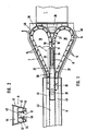
- the transmission according to the exemplary embodiment is equipped with a drive motor 1, on the rotor shaft of which a worm 4 is subsequently formed in one piece via an output shaft region 11.
- This worm 4 engages in the longitudinal direction in a movement transmission member 5 which is guided to move back and forth in a guide 6 running in the longitudinal direction of the shaft.
- the movement transmission element 5 is made available in variable lengths, in which two strands 7 and 8 are brought together or separated via a toothing 9.
- the toothing extends transversely to the longitudinal direction of the strands and is interrupted in the longitudinal direction thereof by a screw counter-thread, so that the toothing 9 extends to the edge regions on both sides thereof.
- the toothing 9 and the worm counter thread 10 are provided on the sides of the strand facing each other when the strands are brought together, such that the teeth of the toothing 9 engage in one another and that the worm thread 10 is formed, each half in the mutually directed sides of the strands 7 and 8 is formed. This is shown in section Figure 2 of DE-PS 3419477.
- the two strands 7 and 8 are held outside the guide 6 with the aid of two deflection guides 19 and 20, with the aid of which the strands 7 and 8 are transferred in parallel position to the movement transmission member after their separation and transverse deformation in storage chambers 43 of the guide 6.
- the ends of the strands 7 and 8 facing away from the drive motor 1 are connected to a connecting member 30 which is common to both strands and which thus represents the beginning of the movement transmission member 5 which is formed and engages in a guide chamber 42 of the guide 6 so as to be longitudinally displaceable.
- the connecting member 30 is provided in its section adjoining the ends of the strands 7 and 8 with a cavity 31 which has the shape of a hollow cylinder extending in the direction of displacement, the jacket wall 32 of which has a larger diameter than the outer diameter of the gear of the worm gear 4.
- This Cavity is also longer in the axial direction than the gear worm 4 in the same direction, so that the worm 4 can rotate freely within the cavity 31, i. H. is out of engagement with the screw mating thread 10 of the strands 7 and 8.
- the threaded connection between the screw 4 and the strands 7 and 8 is thus interrupted, the cavity forms an interrupt area 33.
- the connecting member 30 is designed as a square part, for example made of plastic, and has a tubular body 34, the inner casing wall 32 of which forms the cavity wall, to form the interruption region 33 following the strands 7 and 8.
- the tubular body 34 is connected in a manner not shown to the walls abutting the guide, or in one piece with it this is formed, in principle only two such walls having to be provided, while the end faces form the remaining guide surfaces for contact with the guide wall 45 of the guide chamber 42.
- the tubular body 34 is followed by a working end region 36 of the connecting member 30, which is provided with a connecting section 35, to which a carriage which is displaceably guided along the guide 6 is also connected, which in turn is connected to the object to be moved, for example is articulated to a door leaf.
- the shaft connecting section 11 is provided in its region facing the rotor of the drive motor 1 with a conical shaft section 37 which extends from the worm or driven side the shaft 11 here to this coaxially conically and preferably with a curved surface running to the shaft axis extended toward the drive motor.
- the section 37 merges there in a stepped or non-stepped manner into the rotor shaft of the drive motor 1, which has one of its bearing points in a base part 38 and a bulge 39 provided there.
- the drive motor 1 and, on the other hand, the guide 6 are connected to the base part 38 on its opposite end faces.
- channels 40 are formed in the base part, which connect to the conically enlarged end of the shaft section 37 and through arcuate face-side wall formation merging into straight-line sections towards the storage chambers 43 in the end region, forming the outside walls of the channels 40, while the opposite inner walls are formed by the deflection guides 19 and 20.
- a channel 40 is incorporated in the base part for each of the sections 7 and 8, so that a deflection guide 19 or 20 is formed in the inner area of the arch of each channel, while the opposite channel walls are formed by outside portions of the base part.
- the strands are each formed from a multiplicity of strand sections 14 which are arranged in succession in the strand direction and are connected to one another in an articulated manner and on which the toothing and the half regions of the worm mating thread 10 are formed.
- Figure 2 shows a cross section or an end view of a hollow profile rail 41 forming the guide 6.
- an upper connecting chamber 44 is formed, which can serve to accommodate connecting pieces with which the rail 41 is connected to the base part 38 or with the help of which successive sections of the rail 41 can be connected to one another in the longitudinal direction.
- the guide chamber 42 for receiving the connecting member 30 and the movement transmission member section which follows when it is correspondingly inserted into the guide 6 is formed from the merged strands 7 and 8.
- the guide chamber 42 is connected via a longitudinal slot 12 formed on its underside to a slide guide space 46, in which a slide, not shown, connected to the connecting part 30 is guided so as to be longitudinally displaceable.
- the guide wall 45 on the inside of the guide space 42 is therefore only interrupted by the longitudinal slot 12.
- 42 storage chambers 43 are arranged below the connecting chamber 44 and on both sides of the guide chamber, which, viewed in cross section, are closed all around.
- Figure 1 shows the displacement position of the connecting member 30 and thus the strands 7 and 8 again, in which the threaded connection 4, 10 is interrupted by engagement of the screw 4 in the thread interruption region 33 of the connecting member 30 or the cavity 31 thereof.
- the gear unit is preferably delivered to the place of use pre-assembled. From this shift position, the thread engagement between the thread of the gear worm 4 and the worm mating thread 10 of the strands 7 and 8 can be produced simply by engaging in the longitudinal slot accessible from below outside the carriage, not shown, and thus without the cover, not shown to remove the base part 38 from the outside to the connecting member 30 and this in the direction of the drive motor 1 away.
- FIG. 1 accordingly shows the shift position which is reached when the limit switch is passed incorrectly and which causes the automatic decoupling between motor 1 and motion transmission element 5 and which is set specifically when the preassembled transmission is delivered.
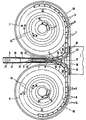
- the transmission according to the second embodiment which is shown in Fig. 3, works with a drive motor 1, a worm 4 and a motion transmission member 5, a guide 6 and two merged in this strands 7 and 8, the teeth 9 in the when merged are arranged on directed sides of the strands and between which a worm thread 10 is formed, as has already been explained in detail in connection with exemplary embodiment 1.
- the two strands 7 and 8 are held outside the guide 6 with the aid of two deflection guides 15 and 20, with the aid of which, after their separation and deformation, they are transferred in the transverse direction into storage drums 50, which are located on both sides of the merging area, i. H. the area of the screw 4 and in front of it.
- channels 40 are formed in the base part, which connect to the conically enlarged end of the shaft section 37 and by arcuate end wall formations open into the storage drums 50 into the space above the floors 51.
- Each base 51 is designed as a circular disk, in the center of which a pivot bearing, designated overall by 56, of practically any configuration is provided.
- the floors 51 of the storage drums 50 lie in a common plane, which in the installed state is directed approximately horizontally at the operating location, so that the axes of rotation emerge approximately vertically.
- the sides of the bottoms 51 facing the viewer are designed as storage surfaces 52 on which the longitudinal sections of the strands 7 and 8, which have been transferred into the store, rest. As soon as the storage-side end region of the strands 7 reaches the associated storage floor, it is guided to the storage floor practically motionless in the direction of rotation.
- each floor 51 is under the load of a spring 53, in such a way that the spring 53 tries to convert the floor in the direction of rotation in which the respective strand around the axis of rotation into the storage drum 50 is recorded.
- This has the consequence that the strands 7 and 8 are kept sliding along the guide inner wall of the respective channel 40 even during the storing movement. There is therefore always a slight tensile load in both directions of movement of the strands 7 and 8, so that the outer walls of the channels 40 and the conical shaft section 37 primarily represent precautionary measures or take up the strands in a leading manner if these are impaired by the rotary bearings of the Floors or a broken spring must reach their storage position under thrust.
- the spring 53 assigned to each of the shelves 51 is located on the underside of the shelf opposite the storage surface 52, i.e. facing away from the viewer, and is indicated in dashed lines in the drawing as a spiral spring which, as shown, preferably extends in a radially outer region and is long, so that A flat force-displacement characteristic is achieved over the winding-up rotation area of the base, with only a small spring force acting on the respective base, so that the tensile stress on the strands and thus their contact pressure on the guide surfaces remains low.
- spiral springs which are preferably designed as leaf spring strips, can be fixed with their inner spiral end to the base part 38 and their outer spiral end to the bottom or vice versa.
- the guide 6 is preferably designed as a profile rail, which has the guide space 42, which is provided in a manner not shown on its lower surface with a longitudinal slot through which the connecting portion 35 of the connecting member 30 in a manner not shown with the carriage or directly with the to be moved Component, in particular a door leaf, for example a door leaf of a garage door that can be moved overhead, is connected.
Landscapes
- Engineering & Computer Science (AREA)
- General Engineering & Computer Science (AREA)
- Mechanical Engineering (AREA)
- Life Sciences & Earth Sciences (AREA)
- Geology (AREA)
- Structural Engineering (AREA)
- Transmission Devices (AREA)
- Forging (AREA)
- Ultra Sonic Daignosis Equipment (AREA)
- Power-Operated Mechanisms For Wings (AREA)
- Milling Processes (AREA)
- Operating, Guiding And Securing Of Roll- Type Closing Members (AREA)
Priority Applications (1)
| Application Number | Priority Date | Filing Date | Title |
|---|---|---|---|
| AT87101212T ATE43882T1 (de) | 1986-02-01 | 1987-01-29 | Getriebe zur ueberfuehrung einer rotatorischen in eine translatorische bewegung. |
Applications Claiming Priority (4)
| Application Number | Priority Date | Filing Date | Title |
|---|---|---|---|
| DE19863603121 DE3603121A1 (de) | 1986-02-01 | 1986-02-01 | Geraet zur ueberfuehrung einer rotatorischen in eine translatorische bewegung mittels zweier in speichertrommeln ueberfuehrbaren straenge |
| DE3603122 | 1986-02-01 | ||
| DE19863603122 DE3603122A1 (de) | 1986-02-01 | 1986-02-01 | Getriebe zur ueberfuehrung einer rotatorischen in eine translatorische bewegung |
| DE3603121 | 1986-02-01 |
Publications (2)
| Publication Number | Publication Date |
|---|---|
| EP0232803A1 EP0232803A1 (de) | 1987-08-19 |
| EP0232803B1 true EP0232803B1 (de) | 1989-06-07 |
Family
ID=25840620
Family Applications (1)
| Application Number | Title | Priority Date | Filing Date |
|---|---|---|---|
| EP87101212A Expired EP0232803B1 (de) | 1986-02-01 | 1987-01-29 | Getriebe zur Überführung einer rotatorischen in eine translatorische Bewegung |
Country Status (6)
| Country | Link |
|---|---|
| US (1) | US4819495A (enExample) |
| EP (1) | EP0232803B1 (enExample) |
| AT (1) | ATE43882T1 (enExample) |
| DE (2) | DE3603121A1 (enExample) |
| ES (1) | ES2009744B3 (enExample) |
| GR (1) | GR3000144T3 (enExample) |
Families Citing this family (188)
| Publication number | Priority date | Publication date | Assignee | Title |
|---|---|---|---|---|
| DE9006391U1 (de) * | 1990-06-06 | 1991-10-10 | Marantec Antriebs-und Steuerungstechnik GmbH & Co, Produktions-oHG, 4834 Marienfeld | Getriebe zur Überführung einer rotatorischen in eine translatorische Bewegung |
| DE4131762C2 (de) * | 1991-09-24 | 1997-05-22 | Winkhaus Fa August | Betätigungsvorrichtung für einen Flügel eines Fensters, einer Tür, einer Lüftungsklappe oder dergleichen |
| DE4210523A1 (de) * | 1992-03-31 | 1993-10-07 | Alltronik Ges Zur Herstellung | Kombinierter Schub- und Zugantrieb |
| DK135995A (da) * | 1995-12-01 | 1997-06-02 | Rasmussen Kann Ind As | Operator med mindst to udstillerelementer til åbning og lukning af svingbare vinduer |
| DK173190B1 (da) * | 1998-04-08 | 2000-03-13 | Velux Ind As | Fremgangsmåde og apparat til tryk- og /eller trækkraftoverføring |
| DK174502B1 (da) * | 1999-03-31 | 2003-04-28 | Vkr Holding As | Vindues- eller døroperator med dobbeltkædeudstiller |
| US20040020612A1 (en) * | 2002-04-17 | 2004-02-05 | Giuseppe Bosio | Ceiling actuator for up-and-over and sectional doors |
| US7082720B2 (en) * | 2002-06-25 | 2006-08-01 | Sumitomo Wiring Systems, Ltd. | Cable guide and power supply apparatus for a vehicle slide door |
| US9060770B2 (en) | 2003-05-20 | 2015-06-23 | Ethicon Endo-Surgery, Inc. | Robotically-driven surgical instrument with E-beam driver |
| US20070084897A1 (en) | 2003-05-20 | 2007-04-19 | Shelton Frederick E Iv | Articulating surgical stapling instrument incorporating a two-piece e-beam firing mechanism |
| US9072535B2 (en) | 2011-05-27 | 2015-07-07 | Ethicon Endo-Surgery, Inc. | Surgical stapling instruments with rotatable staple deployment arrangements |
| US11998198B2 (en) | 2004-07-28 | 2024-06-04 | Cilag Gmbh International | Surgical stapling instrument incorporating a two-piece E-beam firing mechanism |
| US11890012B2 (en) | 2004-07-28 | 2024-02-06 | Cilag Gmbh International | Staple cartridge comprising cartridge body and attached support |
| US10159482B2 (en) | 2005-08-31 | 2018-12-25 | Ethicon Llc | Fastener cartridge assembly comprising a fixed anvil and different staple heights |
| US11246590B2 (en) | 2005-08-31 | 2022-02-15 | Cilag Gmbh International | Staple cartridge including staple drivers having different unfired heights |
| US7669746B2 (en) | 2005-08-31 | 2010-03-02 | Ethicon Endo-Surgery, Inc. | Staple cartridges for forming staples having differing formed staple heights |
| US11793518B2 (en) | 2006-01-31 | 2023-10-24 | Cilag Gmbh International | Powered surgical instruments with firing system lockout arrangements |
| US7845537B2 (en) | 2006-01-31 | 2010-12-07 | Ethicon Endo-Surgery, Inc. | Surgical instrument having recording capabilities |
| US8186555B2 (en) | 2006-01-31 | 2012-05-29 | Ethicon Endo-Surgery, Inc. | Motor-driven surgical cutting and fastening instrument with mechanical closure system |
| US20120292367A1 (en) | 2006-01-31 | 2012-11-22 | Ethicon Endo-Surgery, Inc. | Robotically-controlled end effector |
| US8708213B2 (en) | 2006-01-31 | 2014-04-29 | Ethicon Endo-Surgery, Inc. | Surgical instrument having a feedback system |
| US8992422B2 (en) | 2006-03-23 | 2015-03-31 | Ethicon Endo-Surgery, Inc. | Robotically-controlled endoscopic accessory channel |
| US11980366B2 (en) | 2006-10-03 | 2024-05-14 | Cilag Gmbh International | Surgical instrument |
| US8684253B2 (en) | 2007-01-10 | 2014-04-01 | Ethicon Endo-Surgery, Inc. | Surgical instrument with wireless communication between a control unit of a robotic system and remote sensor |
| US8632535B2 (en) | 2007-01-10 | 2014-01-21 | Ethicon Endo-Surgery, Inc. | Interlock and surgical instrument including same |
| US8540128B2 (en) | 2007-01-11 | 2013-09-24 | Ethicon Endo-Surgery, Inc. | Surgical stapling device with a curved end effector |
| ITBO20070066A1 (it) * | 2007-02-01 | 2008-08-02 | Franceschi Daniele De | Serratura polifunzione e servomotore ad organo attuatore avvolgibile su rocchetto intercambiabile |
| US8011260B2 (en) * | 2007-02-20 | 2011-09-06 | Teleflex Canada Inc. | Double chain linear actuator |
| US8931682B2 (en) | 2007-06-04 | 2015-01-13 | Ethicon Endo-Surgery, Inc. | Robotically-controlled shaft based rotary drive systems for surgical instruments |
| US11564682B2 (en) | 2007-06-04 | 2023-01-31 | Cilag Gmbh International | Surgical stapler device |
| US11849941B2 (en) | 2007-06-29 | 2023-12-26 | Cilag Gmbh International | Staple cartridge having staple cavities extending at a transverse angle relative to a longitudinal cartridge axis |
| US11986183B2 (en) | 2008-02-14 | 2024-05-21 | Cilag Gmbh International | Surgical cutting and fastening instrument comprising a plurality of sensors to measure an electrical parameter |
| JP5410110B2 (ja) | 2008-02-14 | 2014-02-05 | エシコン・エンド−サージェリィ・インコーポレイテッド | Rf電極を有する外科用切断・固定器具 |
| US8636736B2 (en) | 2008-02-14 | 2014-01-28 | Ethicon Endo-Surgery, Inc. | Motorized surgical cutting and fastening instrument |
| US8573465B2 (en) | 2008-02-14 | 2013-11-05 | Ethicon Endo-Surgery, Inc. | Robotically-controlled surgical end effector system with rotary actuated closure systems |
| US9770245B2 (en) | 2008-02-15 | 2017-09-26 | Ethicon Llc | Layer arrangements for surgical staple cartridges |
| US8028510B2 (en) * | 2008-02-27 | 2011-10-04 | Teleflex Canada Inc. | Link for a linear actuator |
| US8210411B2 (en) | 2008-09-23 | 2012-07-03 | Ethicon Endo-Surgery, Inc. | Motor-driven surgical cutting instrument |
| US9386983B2 (en) | 2008-09-23 | 2016-07-12 | Ethicon Endo-Surgery, Llc | Robotically-controlled motorized surgical instrument |
| US11648005B2 (en) | 2008-09-23 | 2023-05-16 | Cilag Gmbh International | Robotically-controlled motorized surgical instrument with an end effector |
| US9005230B2 (en) | 2008-09-23 | 2015-04-14 | Ethicon Endo-Surgery, Inc. | Motorized surgical instrument |
| US8608045B2 (en) | 2008-10-10 | 2013-12-17 | Ethicon Endo-Sugery, Inc. | Powered surgical cutting and stapling apparatus with manually retractable firing system |
| DE102009038785B4 (de) * | 2009-08-25 | 2019-01-31 | Siemens Healthcare Gmbh | Longitudinal-Antrieb für Patientenlagerungssysteme |
| US9248576B2 (en) * | 2010-05-31 | 2016-02-02 | National Institute Of Advanced Industrial Science And Technology | Direct acting extensible and retractable arm mechanism, and robot arm provided with direct acting extensible and retractable arm mechanism |
| US12213666B2 (en) | 2010-09-30 | 2025-02-04 | Cilag Gmbh International | Tissue thickness compensator comprising layers |
| US9629814B2 (en) | 2010-09-30 | 2017-04-25 | Ethicon Endo-Surgery, Llc | Tissue thickness compensator configured to redistribute compressive forces |
| US9386988B2 (en) | 2010-09-30 | 2016-07-12 | Ethicon End-Surgery, LLC | Retainer assembly including a tissue thickness compensator |
| US11812965B2 (en) | 2010-09-30 | 2023-11-14 | Cilag Gmbh International | Layer of material for a surgical end effector |
| US11849952B2 (en) | 2010-09-30 | 2023-12-26 | Cilag Gmbh International | Staple cartridge comprising staples positioned within a compressible portion thereof |
| US10945731B2 (en) | 2010-09-30 | 2021-03-16 | Ethicon Llc | Tissue thickness compensator comprising controlled release and expansion |
| US9848875B2 (en) | 2010-09-30 | 2017-12-26 | Ethicon Llc | Anvil layer attached to a proximal end of an end effector |
| US8695866B2 (en) | 2010-10-01 | 2014-04-15 | Ethicon Endo-Surgery, Inc. | Surgical instrument having a power control circuit |
| US20120261629A1 (en) * | 2011-04-18 | 2012-10-18 | Eric Andkjar | Vertical lift mechanism for use in confined spaces |
| CN104053407B (zh) | 2011-04-29 | 2016-10-26 | 伊西康内外科公司 | 包括定位在其可压缩部分内的钉的钉仓 |
| US11207064B2 (en) | 2011-05-27 | 2021-12-28 | Cilag Gmbh International | Automated end effector component reloading system for use with a robotic system |
| BR112014024102B1 (pt) | 2012-03-28 | 2022-03-03 | Ethicon Endo-Surgery, Inc | Conjunto de cartucho de prendedores para um instrumento cirúrgico, e conjunto de atuador de extremidade para um instrumento cirúrgico |
| CN104334098B (zh) | 2012-03-28 | 2017-03-22 | 伊西康内外科公司 | 包括限定低压强环境的胶囊剂的组织厚度补偿件 |
| US9101358B2 (en) | 2012-06-15 | 2015-08-11 | Ethicon Endo-Surgery, Inc. | Articulatable surgical instrument comprising a firing drive |
| US9289256B2 (en) | 2012-06-28 | 2016-03-22 | Ethicon Endo-Surgery, Llc | Surgical end effectors having angled tissue-contacting surfaces |
| US12383267B2 (en) | 2012-06-28 | 2025-08-12 | Cilag Gmbh International | Robotically powered surgical device with manually-actuatable reversing system |
| US20140001231A1 (en) | 2012-06-28 | 2014-01-02 | Ethicon Endo-Surgery, Inc. | Firing system lockout arrangements for surgical instruments |
| RU2672520C2 (ru) | 2013-03-01 | 2018-11-15 | Этикон Эндо-Серджери, Инк. | Шарнирно поворачиваемые хирургические инструменты с проводящими путями для передачи сигналов |
| JP6345707B2 (ja) | 2013-03-01 | 2018-06-20 | エシコン・エンド−サージェリィ・インコーポレイテッドEthicon Endo−Surgery,Inc. | ソフトストップを備えた外科用器具 |
| US9629629B2 (en) | 2013-03-14 | 2017-04-25 | Ethicon Endo-Surgey, LLC | Control systems for surgical instruments |
| BR112015026109B1 (pt) | 2013-04-16 | 2022-02-22 | Ethicon Endo-Surgery, Inc | Instrumento cirúrgico |
| US9924942B2 (en) | 2013-08-23 | 2018-03-27 | Ethicon Llc | Motor-powered articulatable surgical instruments |
| US12232723B2 (en) | 2014-03-26 | 2025-02-25 | Cilag Gmbh International | Systems and methods for controlling a segmented circuit |
| US20150272571A1 (en) | 2014-03-26 | 2015-10-01 | Ethicon Endo-Surgery, Inc. | Surgical instrument utilizing sensor adaptation |
| US9690362B2 (en) | 2014-03-26 | 2017-06-27 | Ethicon Llc | Surgical instrument control circuit having a safety processor |
| CN106456176B (zh) | 2014-04-16 | 2019-06-28 | 伊西康内外科有限责任公司 | 包括具有不同构型的延伸部的紧固件仓 |
| CN106456158B (zh) | 2014-04-16 | 2019-02-05 | 伊西康内外科有限责任公司 | 包括非一致紧固件的紧固件仓 |
| JP6532889B2 (ja) | 2014-04-16 | 2019-06-19 | エシコン エルエルシーEthicon LLC | 締結具カートリッジ組立体及びステープル保持具カバー配置構成 |
| US10327764B2 (en) | 2014-09-26 | 2019-06-25 | Ethicon Llc | Method for creating a flexible staple line |
| US20150297225A1 (en) | 2014-04-16 | 2015-10-22 | Ethicon Endo-Surgery, Inc. | Fastener cartridges including extensions having different configurations |
| BR112017004361B1 (pt) | 2014-09-05 | 2023-04-11 | Ethicon Llc | Sistema eletrônico para um instrumento cirúrgico |
| US11311294B2 (en) | 2014-09-05 | 2022-04-26 | Cilag Gmbh International | Powered medical device including measurement of closure state of jaws |
| US10105142B2 (en) | 2014-09-18 | 2018-10-23 | Ethicon Llc | Surgical stapler with plurality of cutting elements |
| US11523821B2 (en) | 2014-09-26 | 2022-12-13 | Cilag Gmbh International | Method for creating a flexible staple line |
| US9924944B2 (en) | 2014-10-16 | 2018-03-27 | Ethicon Llc | Staple cartridge comprising an adjunct material |
| US10517594B2 (en) | 2014-10-29 | 2019-12-31 | Ethicon Llc | Cartridge assemblies for surgical staplers |
| US10736636B2 (en) | 2014-12-10 | 2020-08-11 | Ethicon Llc | Articulatable surgical instrument system |
| US10085748B2 (en) | 2014-12-18 | 2018-10-02 | Ethicon Llc | Locking arrangements for detachable shaft assemblies with articulatable surgical end effectors |
| US9987000B2 (en) | 2014-12-18 | 2018-06-05 | Ethicon Llc | Surgical instrument assembly comprising a flexible articulation system |
| US11154301B2 (en) | 2015-02-27 | 2021-10-26 | Cilag Gmbh International | Modular stapling assembly |
| US9808246B2 (en) | 2015-03-06 | 2017-11-07 | Ethicon Endo-Surgery, Llc | Method of operating a powered surgical instrument |
| US10441279B2 (en) | 2015-03-06 | 2019-10-15 | Ethicon Llc | Multiple level thresholds to modify operation of powered surgical instruments |
| US10390825B2 (en) | 2015-03-31 | 2019-08-27 | Ethicon Llc | Surgical instrument with progressive rotary drive systems |
| US10105139B2 (en) | 2015-09-23 | 2018-10-23 | Ethicon Llc | Surgical stapler having downstream current-based motor control |
| US10299878B2 (en) | 2015-09-25 | 2019-05-28 | Ethicon Llc | Implantable adjunct systems for determining adjunct skew |
| US11890015B2 (en) | 2015-09-30 | 2024-02-06 | Cilag Gmbh International | Compressible adjunct with crossing spacer fibers |
| US10172620B2 (en) | 2015-09-30 | 2019-01-08 | Ethicon Llc | Compressible adjuncts with bonding nodes |
| US10736633B2 (en) | 2015-09-30 | 2020-08-11 | Ethicon Llc | Compressible adjunct with looping members |
| US10265068B2 (en) | 2015-12-30 | 2019-04-23 | Ethicon Llc | Surgical instruments with separable motors and motor control circuits |
| US10292704B2 (en) | 2015-12-30 | 2019-05-21 | Ethicon Llc | Mechanisms for compensating for battery pack failure in powered surgical instruments |
| US11213293B2 (en) | 2016-02-09 | 2022-01-04 | Cilag Gmbh International | Articulatable surgical instruments with single articulation link arrangements |
| US10448948B2 (en) | 2016-02-12 | 2019-10-22 | Ethicon Llc | Mechanisms for compensating for drivetrain failure in powered surgical instruments |
| CN108778641A (zh) * | 2016-02-29 | 2018-11-09 | 生活机器人学股份有限公司 | 直动伸缩机构及机械臂机构 |
| US10828028B2 (en) | 2016-04-15 | 2020-11-10 | Ethicon Llc | Surgical instrument with multiple program responses during a firing motion |
| US10357247B2 (en) | 2016-04-15 | 2019-07-23 | Ethicon Llc | Surgical instrument with multiple program responses during a firing motion |
| US20170296173A1 (en) | 2016-04-18 | 2017-10-19 | Ethicon Endo-Surgery, Llc | Method for operating a surgical instrument |
| US10548673B2 (en) | 2016-08-16 | 2020-02-04 | Ethicon Llc | Surgical tool with a display |
| US10537325B2 (en) | 2016-12-21 | 2020-01-21 | Ethicon Llc | Staple forming pocket arrangement to accommodate different types of staples |
| US10758230B2 (en) | 2016-12-21 | 2020-09-01 | Ethicon Llc | Surgical instrument with primary and safety processors |
| JP7010956B2 (ja) | 2016-12-21 | 2022-01-26 | エシコン エルエルシー | 組織をステープル留めする方法 |
| US10588630B2 (en) | 2016-12-21 | 2020-03-17 | Ethicon Llc | Surgical tool assemblies with closure stroke reduction features |
| JP7010957B2 (ja) | 2016-12-21 | 2022-01-26 | エシコン エルエルシー | ロックアウトを備えるシャフトアセンブリ |
| US10639035B2 (en) | 2016-12-21 | 2020-05-05 | Ethicon Llc | Surgical stapling instruments and replaceable tool assemblies thereof |
| US10307170B2 (en) | 2017-06-20 | 2019-06-04 | Ethicon Llc | Method for closed loop control of motor velocity of a surgical stapling and cutting instrument |
| US10779820B2 (en) | 2017-06-20 | 2020-09-22 | Ethicon Llc | Systems and methods for controlling motor speed according to user input for a surgical instrument |
| USD906355S1 (en) | 2017-06-28 | 2020-12-29 | Ethicon Llc | Display screen or portion thereof with a graphical user interface for a surgical instrument |
| US10765427B2 (en) | 2017-06-28 | 2020-09-08 | Ethicon Llc | Method for articulating a surgical instrument |
| US11696759B2 (en) | 2017-06-28 | 2023-07-11 | Cilag Gmbh International | Surgical stapling instruments comprising shortened staple cartridge noses |
| EP3420947B1 (en) | 2017-06-28 | 2022-05-25 | Cilag GmbH International | Surgical instrument comprising selectively actuatable rotatable couplers |
| US10932772B2 (en) | 2017-06-29 | 2021-03-02 | Ethicon Llc | Methods for closed loop velocity control for robotic surgical instrument |
| US11974742B2 (en) | 2017-08-03 | 2024-05-07 | Cilag Gmbh International | Surgical system comprising an articulation bailout |
| US11944300B2 (en) | 2017-08-03 | 2024-04-02 | Cilag Gmbh International | Method for operating a surgical system bailout |
| US11134944B2 (en) | 2017-10-30 | 2021-10-05 | Cilag Gmbh International | Surgical stapler knife motion controls |
| US10842490B2 (en) | 2017-10-31 | 2020-11-24 | Ethicon Llc | Cartridge body design with force reduction based on firing completion |
| US10779826B2 (en) | 2017-12-15 | 2020-09-22 | Ethicon Llc | Methods of operating surgical end effectors |
| US10835330B2 (en) | 2017-12-19 | 2020-11-17 | Ethicon Llc | Method for determining the position of a rotatable jaw of a surgical instrument attachment assembly |
| US12336705B2 (en) | 2017-12-21 | 2025-06-24 | Cilag Gmbh International | Continuous use self-propelled stapling instrument |
| US10682134B2 (en) | 2017-12-21 | 2020-06-16 | Ethicon Llc | Continuous use self-propelled stapling instrument |
| US11207065B2 (en) | 2018-08-20 | 2021-12-28 | Cilag Gmbh International | Method for fabricating surgical stapler anvils |
| US11291440B2 (en) | 2018-08-20 | 2022-04-05 | Cilag Gmbh International | Method for operating a powered articulatable surgical instrument |
| US20200054321A1 (en) | 2018-08-20 | 2020-02-20 | Ethicon Llc | Surgical instruments with progressive jaw closure arrangements |
| US11696761B2 (en) | 2019-03-25 | 2023-07-11 | Cilag Gmbh International | Firing drive arrangements for surgical systems |
| FR3095024B1 (fr) * | 2019-04-10 | 2021-08-06 | Serapid France | Actionneur multilineaire rigide a brin souple |
| US11903581B2 (en) | 2019-04-30 | 2024-02-20 | Cilag Gmbh International | Methods for stapling tissue using a surgical instrument |
| US20200345359A1 (en) | 2019-04-30 | 2020-11-05 | Ethicon Llc | Tissue stop for a surgical instrument |
| US11771419B2 (en) | 2019-06-28 | 2023-10-03 | Cilag Gmbh International | Packaging for a replaceable component of a surgical stapling system |
| US11684434B2 (en) | 2019-06-28 | 2023-06-27 | Cilag Gmbh International | Surgical RFID assemblies for instrument operational setting control |
| US11241235B2 (en) | 2019-06-28 | 2022-02-08 | Cilag Gmbh International | Method of using multiple RFID chips with a surgical assembly |
| WO2021113726A1 (en) | 2019-12-06 | 2021-06-10 | Hello Robot | Mobile manipulation system |
| JP7703232B2 (ja) * | 2019-12-06 | 2025-07-07 | ハロー ロボット インコーポレイテッド | 作動システム及び作動システムを作動させる方法 |
| US11701111B2 (en) | 2019-12-19 | 2023-07-18 | Cilag Gmbh International | Method for operating a surgical stapling instrument |
| US12035913B2 (en) | 2019-12-19 | 2024-07-16 | Cilag Gmbh International | Staple cartridge comprising a deployable knife |
| JP7314857B2 (ja) * | 2020-04-30 | 2023-07-26 | トヨタ自動車株式会社 | 伸縮機構及び移動体 |
| US11883024B2 (en) | 2020-07-28 | 2024-01-30 | Cilag Gmbh International | Method of operating a surgical instrument |
| USD1013170S1 (en) | 2020-10-29 | 2024-01-30 | Cilag Gmbh International | Surgical instrument assembly |
| US11779330B2 (en) | 2020-10-29 | 2023-10-10 | Cilag Gmbh International | Surgical instrument comprising a jaw alignment system |
| US11931025B2 (en) | 2020-10-29 | 2024-03-19 | Cilag Gmbh International | Surgical instrument comprising a releasable closure drive lock |
| US12053175B2 (en) | 2020-10-29 | 2024-08-06 | Cilag Gmbh International | Surgical instrument comprising a stowed closure actuator stop |
| US11896217B2 (en) | 2020-10-29 | 2024-02-13 | Cilag Gmbh International | Surgical instrument comprising an articulation lock |
| US11737751B2 (en) | 2020-12-02 | 2023-08-29 | Cilag Gmbh International | Devices and methods of managing energy dissipated within sterile barriers of surgical instrument housings |
| US11849943B2 (en) | 2020-12-02 | 2023-12-26 | Cilag Gmbh International | Surgical instrument with cartridge release mechanisms |
| US11744581B2 (en) | 2020-12-02 | 2023-09-05 | Cilag Gmbh International | Powered surgical instruments with multi-phase tissue treatment |
| US11653915B2 (en) | 2020-12-02 | 2023-05-23 | Cilag Gmbh International | Surgical instruments with sled location detection and adjustment features |
| US11944296B2 (en) | 2020-12-02 | 2024-04-02 | Cilag Gmbh International | Powered surgical instruments with external connectors |
| US12471982B2 (en) | 2020-12-02 | 2025-11-18 | Cilag Gmbh International | Method for tissue treatment by surgical instrument |
| US11890010B2 (en) | 2020-12-02 | 2024-02-06 | Cllag GmbH International | Dual-sided reinforced reload for surgical instruments |
| US11701113B2 (en) | 2021-02-26 | 2023-07-18 | Cilag Gmbh International | Stapling instrument comprising a separate power antenna and a data transfer antenna |
| US12324580B2 (en) | 2021-02-26 | 2025-06-10 | Cilag Gmbh International | Method of powering and communicating with a staple cartridge |
| US11751869B2 (en) | 2021-02-26 | 2023-09-12 | Cilag Gmbh International | Monitoring of multiple sensors over time to detect moving characteristics of tissue |
| US11696757B2 (en) | 2021-02-26 | 2023-07-11 | Cilag Gmbh International | Monitoring of internal systems to detect and track cartridge motion status |
| US11950777B2 (en) | 2021-02-26 | 2024-04-09 | Cilag Gmbh International | Staple cartridge comprising an information access control system |
| US11744583B2 (en) | 2021-02-26 | 2023-09-05 | Cilag Gmbh International | Distal communication array to tune frequency of RF systems |
| US11749877B2 (en) | 2021-02-26 | 2023-09-05 | Cilag Gmbh International | Stapling instrument comprising a signal antenna |
| US11793514B2 (en) | 2021-02-26 | 2023-10-24 | Cilag Gmbh International | Staple cartridge comprising sensor array which may be embedded in cartridge body |
| US11730473B2 (en) | 2021-02-26 | 2023-08-22 | Cilag Gmbh International | Monitoring of manufacturing life-cycle |
| US11980362B2 (en) | 2021-02-26 | 2024-05-14 | Cilag Gmbh International | Surgical instrument system comprising a power transfer coil |
| US11723657B2 (en) | 2021-02-26 | 2023-08-15 | Cilag Gmbh International | Adjustable communication based on available bandwidth and power capacity |
| US12108951B2 (en) | 2021-02-26 | 2024-10-08 | Cilag Gmbh International | Staple cartridge comprising a sensing array and a temperature control system |
| US11812964B2 (en) | 2021-02-26 | 2023-11-14 | Cilag Gmbh International | Staple cartridge comprising a power management circuit |
| US11737749B2 (en) | 2021-03-22 | 2023-08-29 | Cilag Gmbh International | Surgical stapling instrument comprising a retraction system |
| US11723658B2 (en) | 2021-03-22 | 2023-08-15 | Cilag Gmbh International | Staple cartridge comprising a firing lockout |
| US11717291B2 (en) | 2021-03-22 | 2023-08-08 | Cilag Gmbh International | Staple cartridge comprising staples configured to apply different tissue compression |
| US11826042B2 (en) | 2021-03-22 | 2023-11-28 | Cilag Gmbh International | Surgical instrument comprising a firing drive including a selectable leverage mechanism |
| US11826012B2 (en) | 2021-03-22 | 2023-11-28 | Cilag Gmbh International | Stapling instrument comprising a pulsed motor-driven firing rack |
| US11759202B2 (en) | 2021-03-22 | 2023-09-19 | Cilag Gmbh International | Staple cartridge comprising an implantable layer |
| US11806011B2 (en) | 2021-03-22 | 2023-11-07 | Cilag Gmbh International | Stapling instrument comprising tissue compression systems |
| US11849945B2 (en) | 2021-03-24 | 2023-12-26 | Cilag Gmbh International | Rotary-driven surgical stapling assembly comprising eccentrically driven firing member |
| US11786243B2 (en) | 2021-03-24 | 2023-10-17 | Cilag Gmbh International | Firing members having flexible portions for adapting to a load during a surgical firing stroke |
| US11744603B2 (en) | 2021-03-24 | 2023-09-05 | Cilag Gmbh International | Multi-axis pivot joints for surgical instruments and methods for manufacturing same |
| US11896218B2 (en) | 2021-03-24 | 2024-02-13 | Cilag Gmbh International | Method of using a powered stapling device |
| US11793516B2 (en) | 2021-03-24 | 2023-10-24 | Cilag Gmbh International | Surgical staple cartridge comprising longitudinal support beam |
| US12102323B2 (en) | 2021-03-24 | 2024-10-01 | Cilag Gmbh International | Rotary-driven surgical stapling assembly comprising a floatable component |
| US11896219B2 (en) | 2021-03-24 | 2024-02-13 | Cilag Gmbh International | Mating features between drivers and underside of a cartridge deck |
| US11832816B2 (en) | 2021-03-24 | 2023-12-05 | Cilag Gmbh International | Surgical stapling assembly comprising nonplanar staples and planar staples |
| US11903582B2 (en) | 2021-03-24 | 2024-02-20 | Cilag Gmbh International | Leveraging surfaces for cartridge installation |
| US11857183B2 (en) | 2021-03-24 | 2024-01-02 | Cilag Gmbh International | Stapling assembly components having metal substrates and plastic bodies |
| US11849944B2 (en) | 2021-03-24 | 2023-12-26 | Cilag Gmbh International | Drivers for fastener cartridge assemblies having rotary drive screws |
| US11786239B2 (en) | 2021-03-24 | 2023-10-17 | Cilag Gmbh International | Surgical instrument articulation joint arrangements comprising multiple moving linkage features |
| US11723662B2 (en) | 2021-05-28 | 2023-08-15 | Cilag Gmbh International | Stapling instrument comprising an articulation control display |
| CN113459127B (zh) * | 2021-07-31 | 2022-03-18 | 西南科技大学 | 自生长软硬一体化机器人及其应用 |
| US11980363B2 (en) | 2021-10-18 | 2024-05-14 | Cilag Gmbh International | Row-to-row staple array variations |
| US12432790B2 (en) | 2021-10-28 | 2025-09-30 | Cilag Gmbh International | Method and device for transmitting UART communications over a security short range wireless communication |
| US12089841B2 (en) | 2021-10-28 | 2024-09-17 | Cilag CmbH International | Staple cartridge identification systems |
| US11937816B2 (en) | 2021-10-28 | 2024-03-26 | Cilag Gmbh International | Electrical lead arrangements for surgical instruments |
Family Cites Families (14)
| Publication number | Priority date | Publication date | Assignee | Title |
|---|---|---|---|---|
| FR593487A (enExample) * | 1925-08-24 | |||
| US2045261A (en) * | 1935-02-18 | 1936-06-23 | Harry W Clute | Push-pull link transmission |
| US2131261A (en) * | 1937-04-05 | 1938-09-27 | Curtis Companies Inc | Link chain |
| DE860111C (de) * | 1942-07-09 | 1953-01-26 | Daniel Ernst | Geraet zum Pruefen der Teilungen von Zahnraedern |
| US2574657A (en) * | 1945-10-23 | 1951-11-13 | Harold C Pierce | Flexible power transmitting mechanism |
| DE946661C (de) * | 1953-11-17 | 1956-08-02 | Selve Fa Ernst | Einlassgurtroller mit vorgewoelbter Abdeckung |
| US2832590A (en) * | 1955-11-09 | 1958-04-29 | H B Ives Company | Casement window operators |
| US3174742A (en) * | 1963-04-05 | 1965-03-23 | Golde Gmbh H T | Power operated regulating mechanism |
| US4311225A (en) * | 1978-06-14 | 1982-01-19 | Hitachi, Ltd. | Device for driving driven member by roller chain |
| JPS5545946A (en) * | 1978-09-29 | 1980-03-31 | Hitachi Ltd | Roller chain driver |
| US4414778A (en) * | 1981-04-13 | 1983-11-15 | The Alliance Manufacturing Company, Inc. | Tape drive door operator |
| US4520684A (en) * | 1983-02-03 | 1985-06-04 | The Alliance Manufacturing Company, Inc. | Tape drive closure operator |
| JPS608560A (ja) * | 1983-06-29 | 1985-01-17 | Yoshihiko Maejima | 1対のチエンによるガイドレス型直線運動機構 |
| DE3419477C1 (de) * | 1984-05-24 | 1985-11-28 | Hörmann KG Antriebs- und Steuerungstechnik, 4834 Harsewinkel | Getriebe zur UEberfuehrung einer rotatorischen in eine translatorische Bewegung |
-
1986
- 1986-02-01 DE DE19863603121 patent/DE3603121A1/de active Granted
-
1987
- 1987-01-29 ES ES87101212T patent/ES2009744B3/es not_active Expired
- 1987-01-29 DE DE8787101212T patent/DE3760227D1/de not_active Expired
- 1987-01-29 EP EP87101212A patent/EP0232803B1/de not_active Expired
- 1987-01-29 AT AT87101212T patent/ATE43882T1/de not_active IP Right Cessation
- 1987-01-30 US US07/008,935 patent/US4819495A/en not_active Expired - Lifetime
-
1989
- 1989-09-05 GR GR89400160T patent/GR3000144T3/el unknown
Also Published As
| Publication number | Publication date |
|---|---|
| DE3760227D1 (en) | 1989-07-13 |
| ATE43882T1 (de) | 1989-06-15 |
| US4819495A (en) | 1989-04-11 |
| DE3603121A1 (de) | 1987-10-29 |
| ES2009744A4 (es) | 1989-10-16 |
| GR3000144T3 (en) | 1990-11-29 |
| EP0232803A1 (de) | 1987-08-19 |
| DE3603121C2 (enExample) | 1988-07-14 |
| ES2009744B3 (es) | 1989-12-01 |
Similar Documents
| Publication | Publication Date | Title |
|---|---|---|
| EP0232803B1 (de) | Getriebe zur Überführung einer rotatorischen in eine translatorische Bewegung | |
| EP0165497B1 (de) | Getriebe zur Überführung einer rotatorischen in eine translatorische Bewegung | |
| DE69703635T2 (de) | Angetriebene Verriegelungsvorrichtung für Fahrzeuge mit verbesserten Mitteln zur Begrenzung der Bewegung eines Riegels | |
| DE2913887C2 (enExample) | ||
| DE60030215T2 (de) | Antriebsmechanismus und Führungsschiene für ein Rollo | |
| EP1298274B1 (de) | Flügeltürantrieb mit Federschliessung | |
| DE2913885A1 (de) | Lamellenjalousie mit senkrecht angeordneten lamellen | |
| DE202005002585U1 (de) | Elektromotorischer Linearantrieb | |
| DE2802773A1 (de) | Nichtreversible antriebsvorrichtung, insbesondere fuer das kraftuebertragungselement von elektrischen anlassern fuer verbrennungsmotoren | |
| EP0864026B1 (de) | Bowdenrohr-fensterheber mit seillängenausgleich | |
| DE3501454A1 (de) | Geraet zur ueberfuehrung einer rotatorischen in eine translatorische bewegung und umgekehrt | |
| DE102005007205B3 (de) | Elektromotorischer Linearantrieb | |
| EP3405698B1 (de) | Aktuator mit hohlschnecke | |
| EP0853201B1 (de) | Vorrichtung zum automatischen, stufenweisen Seillängenausgleich eines Bowdenzugsystems | |
| DE3430754A1 (de) | Vorrichtung zum motorgetriebenen OEffnen und Schliessen einer Kraftfahrzeug-Fenstergardine | |
| EP0563517A1 (de) | Kombinierter Schub- und Zugantrieb | |
| DE3603122C2 (enExample) | ||
| EP1517068A2 (de) | Kraftfahrzeuggetriebe-Stellvorrichtung | |
| DE69011828T2 (de) | Automatische Arretierungsvorrichtung für einen elektrischen Motor nach einer bestimmten Anzahl von Umdrehungen. | |
| DE8602627U1 (de) | Getriebe zur Überführung einer rotatorischen in eine translatorische Bewegung | |
| DE8602626U1 (de) | Gerät zur Überführung einer rotatorischen in eine translatorische Bewegung mittels zweier in Speichertrommeln überführbaren Stränge | |
| DE19817933A1 (de) | Seilführung | |
| EP1310702A1 (de) | Bremsvorrichtung für eine rotative Antriebsvorrichtung | |
| EP1357316B1 (de) | Stelleinrichtung | |
| DE2517134C2 (de) | Antrieb für einen elektrischen Leistungsschalter |
Legal Events
| Date | Code | Title | Description |
|---|---|---|---|
| PUAI | Public reference made under article 153(3) epc to a published international application that has entered the european phase |
Free format text: ORIGINAL CODE: 0009012 |
|
| AK | Designated contracting states |
Kind code of ref document: A1 Designated state(s): AT BE CH DE ES FR GB GR IT LI LU NL SE |
|
| 17P | Request for examination filed |
Effective date: 19870909 |
|
| 17Q | First examination report despatched |
Effective date: 19881027 |
|
| GRAA | (expected) grant |
Free format text: ORIGINAL CODE: 0009210 |
|
| AK | Designated contracting states |
Kind code of ref document: B1 Designated state(s): AT BE CH DE ES FR GB GR IT LI LU NL SE |
|
| REF | Corresponds to: |
Ref document number: 43882 Country of ref document: AT Date of ref document: 19890615 Kind code of ref document: T |
|
| REF | Corresponds to: |
Ref document number: 3760227 Country of ref document: DE Date of ref document: 19890713 |
|
| ET | Fr: translation filed | ||
| ITF | It: translation for a ep patent filed | ||
| ET1 | Fr: translation filed ** revision of the translation of the patent or the claims | ||
| GBT | Gb: translation of ep patent filed (gb section 77(6)(a)/1977) | ||
| PLBE | No opposition filed within time limit |
Free format text: ORIGINAL CODE: 0009261 |
|
| STAA | Information on the status of an ep patent application or granted ep patent |
Free format text: STATUS: NO OPPOSITION FILED WITHIN TIME LIMIT |
|
| REG | Reference to a national code |
Ref country code: GR Ref legal event code: FG4A Free format text: 3000144 |
|
| 26N | No opposition filed | ||
| EPTA | Lu: last paid annual fee | ||
| EAL | Se: european patent in force in sweden |
Ref document number: 87101212.6 |
|
| ITTA | It: last paid annual fee | ||
| REG | Reference to a national code |
Ref country code: FR Ref legal event code: CD |
|
| REG | Reference to a national code |
Ref country code: CH Ref legal event code: PFA Free format text: HOERMANN KG ANTRIEBS- U. STEUERUNGSTECHNIK TRANSFER- MARANTEC ANTRIEBS- UND STEUERUNGSTECHNIK GMBH & CO. KG. |
|
| NLT1 | Nl: modifications of names registered in virtue of documents presented to the patent office pursuant to art. 16 a, paragraph 1 |
Owner name: MARANTEC ANTRIEBS- UND STEUERUNGSTECHNIK GMBH & CO |
|
| REG | Reference to a national code |
Ref country code: ES Ref legal event code: PC2A |
|
| REG | Reference to a national code |
Ref country code: FR Ref legal event code: CD |
|
| REG | Reference to a national code |
Ref country code: ES Ref legal event code: PC2A |
|
| BECN | Be: change of holder's name |
Effective date: 20010531 |
|
| REG | Reference to a national code |
Ref country code: GB Ref legal event code: IF02 |
|
| PGFP | Annual fee paid to national office [announced via postgrant information from national office to epo] |
Ref country code: GR Payment date: 20021223 Year of fee payment: 17 |
|
| PGFP | Annual fee paid to national office [announced via postgrant information from national office to epo] |
Ref country code: GB Payment date: 20021224 Year of fee payment: 17 |
|
| PGFP | Annual fee paid to national office [announced via postgrant information from national office to epo] |
Ref country code: FR Payment date: 20030116 Year of fee payment: 17 Ref country code: ES Payment date: 20030116 Year of fee payment: 17 |
|
| PGFP | Annual fee paid to national office [announced via postgrant information from national office to epo] |
Ref country code: SE Payment date: 20030120 Year of fee payment: 17 Ref country code: BE Payment date: 20030120 Year of fee payment: 17 |
|
| PGFP | Annual fee paid to national office [announced via postgrant information from national office to epo] |
Ref country code: NL Payment date: 20030121 Year of fee payment: 17 Ref country code: AT Payment date: 20030121 Year of fee payment: 17 |
|
| PGFP | Annual fee paid to national office [announced via postgrant information from national office to epo] |
Ref country code: LU Payment date: 20030124 Year of fee payment: 17 |
|
| PGFP | Annual fee paid to national office [announced via postgrant information from national office to epo] |
Ref country code: DE Payment date: 20030130 Year of fee payment: 17 Ref country code: CH Payment date: 20030130 Year of fee payment: 17 |
|
| PG25 | Lapsed in a contracting state [announced via postgrant information from national office to epo] |
Ref country code: LU Free format text: LAPSE BECAUSE OF NON-PAYMENT OF DUE FEES Effective date: 20040129 Ref country code: GB Free format text: LAPSE BECAUSE OF NON-PAYMENT OF DUE FEES Effective date: 20040129 Ref country code: AT Free format text: LAPSE BECAUSE OF NON-PAYMENT OF DUE FEES Effective date: 20040129 |
|
| PG25 | Lapsed in a contracting state [announced via postgrant information from national office to epo] |
Ref country code: SE Free format text: LAPSE BECAUSE OF NON-PAYMENT OF DUE FEES Effective date: 20040130 Ref country code: ES Free format text: LAPSE BECAUSE OF NON-PAYMENT OF DUE FEES Effective date: 20040130 |
|
| PG25 | Lapsed in a contracting state [announced via postgrant information from national office to epo] |
Ref country code: LI Free format text: LAPSE BECAUSE OF NON-PAYMENT OF DUE FEES Effective date: 20040131 Ref country code: CH Free format text: LAPSE BECAUSE OF NON-PAYMENT OF DUE FEES Effective date: 20040131 Ref country code: BE Free format text: LAPSE BECAUSE OF NON-PAYMENT OF DUE FEES Effective date: 20040131 |
|
| BERE | Be: lapsed |
Owner name: *MARANTEC ANTRIEBS-UND STEUERUNGSTECHNIK G.M.B.H. Effective date: 20040131 |
|
| PG25 | Lapsed in a contracting state [announced via postgrant information from national office to epo] |
Ref country code: NL Free format text: LAPSE BECAUSE OF NON-PAYMENT OF DUE FEES Effective date: 20040801 |
|
| PG25 | Lapsed in a contracting state [announced via postgrant information from national office to epo] |
Ref country code: DE Free format text: LAPSE BECAUSE OF NON-PAYMENT OF DUE FEES Effective date: 20040803 |
|
| PG25 | Lapsed in a contracting state [announced via postgrant information from national office to epo] |
Ref country code: GR Free format text: LAPSE BECAUSE OF NON-PAYMENT OF DUE FEES Effective date: 20040804 |
|
| EUG | Se: european patent has lapsed | ||
| GBPC | Gb: european patent ceased through non-payment of renewal fee |
Effective date: 20040129 |
|
| REG | Reference to a national code |
Ref country code: CH Ref legal event code: PL |
|
| PG25 | Lapsed in a contracting state [announced via postgrant information from national office to epo] |
Ref country code: FR Free format text: LAPSE BECAUSE OF NON-PAYMENT OF DUE FEES Effective date: 20040930 |
|
| NLV4 | Nl: lapsed or anulled due to non-payment of the annual fee |
Effective date: 20040801 |
|
| REG | Reference to a national code |
Ref country code: FR Ref legal event code: ST |
|
| PG25 | Lapsed in a contracting state [announced via postgrant information from national office to epo] |
Ref country code: IT Free format text: LAPSE BECAUSE OF NON-PAYMENT OF DUE FEES;WARNING: LAPSES OF ITALIAN PATENTS WITH EFFECTIVE DATE BEFORE 2007 MAY HAVE OCCURRED AT ANY TIME BEFORE 2007. THE CORRECT EFFECTIVE DATE MAY BE DIFFERENT FROM THE ONE RECORDED. Effective date: 20050129 |
|
| REG | Reference to a national code |
Ref country code: ES Ref legal event code: FD2A Effective date: 20040130 |