EP0232700A2 - Anlage zur Herstellung von Kompost aus organischen Abfallstoffen - Google Patents
Anlage zur Herstellung von Kompost aus organischen Abfallstoffen Download PDFInfo
- Publication number
- EP0232700A2 EP0232700A2 EP87100039A EP87100039A EP0232700A2 EP 0232700 A2 EP0232700 A2 EP 0232700A2 EP 87100039 A EP87100039 A EP 87100039A EP 87100039 A EP87100039 A EP 87100039A EP 0232700 A2 EP0232700 A2 EP 0232700A2
- Authority
- EP
- European Patent Office
- Prior art keywords
- silo
- plant according
- mixing tool
- compost
- mixing
- Prior art date
- Legal status (The legal status is an assumption and is not a legal conclusion. Google has not performed a legal analysis and makes no representation as to the accuracy of the status listed.)
- Granted
Links
Images


Classifications
-
- C—CHEMISTRY; METALLURGY
- C05—FERTILISERS; MANUFACTURE THEREOF
- C05F—ORGANIC FERTILISERS NOT COVERED BY SUBCLASSES C05B, C05C, e.g. FERTILISERS FROM WASTE OR REFUSE
- C05F17/00—Preparation of fertilisers characterised by biological or biochemical treatment steps, e.g. composting or fermentation
- C05F17/90—Apparatus therefor
-
- B—PERFORMING OPERATIONS; TRANSPORTING
- B01—PHYSICAL OR CHEMICAL PROCESSES OR APPARATUS IN GENERAL
- B01F—MIXING, e.g. DISSOLVING, EMULSIFYING OR DISPERSING
- B01F27/00—Mixers with rotary stirring devices in fixed receptacles; Kneaders
- B01F27/05—Stirrers
- B01F27/11—Stirrers characterised by the configuration of the stirrers
- B01F27/114—Helically shaped stirrers, i.e. stirrers comprising a helically shaped band or helically shaped band sections
-
- B—PERFORMING OPERATIONS; TRANSPORTING
- B01—PHYSICAL OR CHEMICAL PROCESSES OR APPARATUS IN GENERAL
- B01F—MIXING, e.g. DISSOLVING, EMULSIFYING OR DISPERSING
- B01F27/00—Mixers with rotary stirring devices in fixed receptacles; Kneaders
- B01F27/80—Mixers with rotary stirring devices in fixed receptacles; Kneaders with stirrers rotating about a substantially vertical axis
- B01F27/83—Mixers with rotary stirring devices in fixed receptacles; Kneaders with stirrers rotating about a substantially vertical axis the stirrers being additionally moved radially, or oscillating about an axis perpendicular to the stirrer axis
-
- C—CHEMISTRY; METALLURGY
- C05—FERTILISERS; MANUFACTURE THEREOF
- C05F—ORGANIC FERTILISERS NOT COVERED BY SUBCLASSES C05B, C05C, e.g. FERTILISERS FROM WASTE OR REFUSE
- C05F17/00—Preparation of fertilisers characterised by biological or biochemical treatment steps, e.g. composting or fermentation
- C05F17/90—Apparatus therefor
- C05F17/964—Constructional parts, e.g. floors, covers or doors
-
- Y—GENERAL TAGGING OF NEW TECHNOLOGICAL DEVELOPMENTS; GENERAL TAGGING OF CROSS-SECTIONAL TECHNOLOGIES SPANNING OVER SEVERAL SECTIONS OF THE IPC; TECHNICAL SUBJECTS COVERED BY FORMER USPC CROSS-REFERENCE ART COLLECTIONS [XRACs] AND DIGESTS
- Y02—TECHNOLOGIES OR APPLICATIONS FOR MITIGATION OR ADAPTATION AGAINST CLIMATE CHANGE
- Y02P—CLIMATE CHANGE MITIGATION TECHNOLOGIES IN THE PRODUCTION OR PROCESSING OF GOODS
- Y02P20/00—Technologies relating to chemical industry
- Y02P20/141—Feedstock
- Y02P20/145—Feedstock the feedstock being materials of biological origin
-
- Y—GENERAL TAGGING OF NEW TECHNOLOGICAL DEVELOPMENTS; GENERAL TAGGING OF CROSS-SECTIONAL TECHNOLOGIES SPANNING OVER SEVERAL SECTIONS OF THE IPC; TECHNICAL SUBJECTS COVERED BY FORMER USPC CROSS-REFERENCE ART COLLECTIONS [XRACs] AND DIGESTS
- Y02—TECHNOLOGIES OR APPLICATIONS FOR MITIGATION OR ADAPTATION AGAINST CLIMATE CHANGE
- Y02W—CLIMATE CHANGE MITIGATION TECHNOLOGIES RELATED TO WASTEWATER TREATMENT OR WASTE MANAGEMENT
- Y02W30/00—Technologies for solid waste management
- Y02W30/40—Bio-organic fraction processing; Production of fertilisers from the organic fraction of waste or refuse
Definitions
- the waste materials to be composted are fed via a distributor belt to a trough conveyor belt which is divided into fermentation cells and which the rotting hall in a predetermined rotting time passes through and discards the finished compost at the other end of the hall. Since the throughput time of the waste to be composted must last from one day to two or even three weeks, it is easy to see that this system is very large, expensive and, due to the many moving parts, also prone to failure. Troubleshooting is a tedious and uncomfortable job, because the rotten hall has high temperatures of up to 70 ° C and high air humidity. There are always gases that also make the fault clearance and maintenance work dangerous.
- the present invention aims to provide a plant for the production of compost from organic waste materials, which essentially with known means available on the market, i.e. can be produced inexpensively, is easy to maintain and produces high-quality compost.
- the shredded organic household waste 3 is introduced into a rectangular silo 1.
- the shredder process which is unique, is suitable for shredding the waste produces better humus than the cutting or Häxler method.
- a mixing tool 5 Attached to the bridge 2 of a traveling crane that can be moved along the silo 1 is a mixing tool 5 with its free end that extends into the vicinity of the silo floor.
- This mixing tool 5 can be moved transversely to the silo 1 on the bridge 2.
- the mixing tool 5 is formed into a drilling part 6.
- the upper part of the mixing tool 5 is a screw conveyor-like mixing screw that is rotatable about its axis 4. Almost the entire interior of the silo 1 can be reached for the approximately vertical mixing tool 5.
- the movement of the mixing tool 5 is controlled by electrical control means such that it moves through almost the entire interior of the silo 1 in a predetermined time.
- the mixing tool 5 brings about a mixing of the layers of waste 3 lying one above the other and at the same time leads to its aeration, which intensifies the biological rotting thereof. So that only the upper layers in the silo 1 can be processed if necessary, the mixing tool 5 can expediently be pushed back and forth in the vertical direction.
- An automatically operating scratching device 7 is arranged horizontally on the bottom of the silo 1 under the waste 3.
- This scratching device 7 consists of at least one slide 9 which can be moved back and forth on the bottom of the silo 1 and which is equipped with a plurality of scratches 10 with a wedge-shaped cross section. The cutting edges of the scratches 10 are opposite to the direction of conveyance of the compost. Due to the movement of the slide 9, the compost is guided into a collecting screw 8 arranged outside the silo 1.
- the system is covered by a roof 11 or in one Hall stands.
- the silo 1 advantageously has a wall height of 2.5 m and a width of 10 m. The length can then be freely selected as required. Of course, a silo that is wider and taller is also conceivable. With a silo with a wall height of 4 m, for example, additional ventilation of the silo content would have to be provided.
- the system described above ensures the greatest possible automation and space utilization and the avoidance of artificial auxiliary agents such as composting materials, the conversion of organic waste materials into high-quality compost.
- the investment costs are relatively low and the system is low-maintenance and reliable.
- the drive components are easily accessible outside the silo for any repair work. If necessary, the system can be easily expanded by extending the silo.
Landscapes
- Chemical & Material Sciences (AREA)
- Chemical Kinetics & Catalysis (AREA)
- Engineering & Computer Science (AREA)
- Health & Medical Sciences (AREA)
- Biochemistry (AREA)
- Biotechnology (AREA)
- Life Sciences & Earth Sciences (AREA)
- General Chemical & Material Sciences (AREA)
- Microbiology (AREA)
- Molecular Biology (AREA)
- Organic Chemistry (AREA)
- Fertilizers (AREA)
- Processing Of Solid Wastes (AREA)
Abstract
Description
- Das dringende Erfordernis die organischen Haushaltabfälle in Kompost zu verwandeln wird allgemein anerkannt. Da die organischen Haushaltabfälle bis zu 90% aus Wasser bestehen, ist das Verbrennen dieser Abfälle, wie das bisher praktiziert wurde, höchst unrentabel.
- In einer bekannten Kompostieranlage werden organische Siedlungsabfälle in Form eines fortlaufenden, gepressten Stranges zwangsläufig als nebeneinander- und übereinanderliegende Stränge in eine vorzugsweise geschlossene und klimatisierte Rottehalle eingepresst und nach einer bestimmten Verweildauer durch Einpressen frischen Materials wieder aus der Rottehalle ausgestossen. Diese bekannte Anlage ist nicht nur kompliziert, sondern auch teuer in der Herstellung, denn es ist eine sehr grosse, speziell für diesen Zweck anzufertigende Presse erforderlich. Ferner muss die ganze Rottehalle mit Führungen für den gepressten Strang versehen sein, da dieser zum abbröckeln neigt, was zu Störungen in der Anlage führen kann.
- In einer anderen Kompostieranlage werden die zu kompostierenden Abfallstoffe über ein Verteilerband einem in Fermentierungszellen unterteiltes Trogförderband zugeführt, welches die Rottehalle in einer vorbestimmten Rottezeit durchläuft und am anderen Hallenende den fertigen Kompost abwirft. Da die Durchlaufdauer der zu kompostierenden Abfälle von einem Tag bis zu zwei oder gar drei Wochen dauern muss, ist leicht zu ersehen, dass diese Anlage sehr gross, teuer und, bedingt durch die vielen beweglichen Teile, auch störungsanfällig ist. Das beheben von Störungen ist aber eine mühsame und unangehmene Arbeit, denn in der Rottehalle herrschen hohe Temperaturen bis zu 70° C bei hoher Luftfeuchtigkeit. Es sind auch stets Gase vorhanden, die die Entstörungs- und Wartungsarbeit darüberhinaus auch noch gefährlich machen.
- Die vorliegende Erfindung bezweckt eine Anlage zur Herstellung von Kompost aus organischen Abfallstoffen zu schaffen, die im wesentlichen mit bekannten auf dem Markt erhältlichen Mitteln, d.h. kostengünstig hergestellt werden kann, leicht zu warten ist und einen hochwertigen Kompost ergibt.
- Die erfindungsgemässe Anlage entspricht den kennzeichnenden Merkmalen des Patentanspruchs 1.
- Nachfolgend wird anhand von drei Zeichnungsfiguren ein Ausführungsbeispiel der erfindungsgemässen Anlage beschrieben.
- Fig. 1 zeigt eine Ansicht der Anlage,
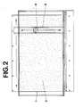
- Fig. 2 zeigt eine Draufsicht der Anlage, und
- Fig. 3 zeigt das Mischwerkzeug.
- In ein rechteckiges Silo 1 wird der zerkleinerte organische Haushaltabfall 3 eingebracht. Zur Zerkleinerung des Abfalls eignet sich das Schredder-Verfahren, welches eindeutig besseren Humus ergibt als das Schneide- bzw. Häxlerverfahren.
- An der Brücke 2 eines entlang des Silos 1 verfahrbaren Laufkrans ist ein mit seinem freien Ende bis in die Nähe des Silobodens reichendes Mischwerkzeug 5 angebracht. Dieses Mischwerkzeug 5 ist an der Brücke 2 quer zum Silo 1 verfahrbar. An seinem freien Ende ist das Mischwerkzeug 5 zu einem Bohrteil 6 ausgebildet. Der obere Teil des Mischwerkzeugs 5 ist eine förderschneckenartige Mischschnecke, die um ihre Achse 4 drehbar ist. Annähernd der ganze Innenraum des Silos 1 ist für das annähernd senkrecht stehende Mischwerkzeug 5 erreichbar. Die Bewegung des Mischwerkzeugs 5 wird durch elektrische Steuermittel so gesteuert, dass dieses sich in einer vorbestimmten Zeit durch annähernd den ganzen Innenraum des Silos 1 bewegt. Das Mischwerkzeug 5 bewirkt eine Vermischung der übereinanderliegenden Schichten des Abfalls 3 und führt zugleich zu dessen Belüfung, was die biologische Verrottung desselben intensiviert. Damit bei Bedarf nur die oberen Schichten im Silo 1 bearbeitet werden können, ist das Mischwerkzeug 5 zweckmässig in vertikaler Richtung hin- und herverschiebbar.
- Unter dem Abfall 3 ist eine automatisch arbeitende Kratz-Vorrichtung 7 horizontal auf dem Boden des Silos 1 angeordnet. Diese Kratz-Vorrichtung 7 besteht aus mindestens einem auf dem Boden des Silos 1 hin- und herbewegbaren Schieber 9, der mit einer Mehrzahl von Kratzern 10 mit keilförmigem Querschnitt besetzt ist. Die Schneiden der Kratzer 10 liegen entgegen der Förderrichtung des Kompostes. Durch die Bewegung des Schiebers 9 wird der Kompost in eine ausserhalb des Silos 1 angeordnete Sammelschnecke 8 geführt.
- Zum Schutz gegen Witterungseinflüsse und gegebenenfalls auch zur Verringerung von Geruchsimmissionen ist es vorteilhaft, wenn die Anlage von einem Dach 11 bedeckt ist oder in einer Halle steht.
- Der Silo 1 hat vorteilhaft eine Wandhöhe von 2,5 m und eine Breite von 10 m. Die Länge kann dann nach Bedarf frei gewählt werden. Selbstverständlich ist auch ein Silo denkbar, der breiter und höher ist. Bei einem Silo mit einer Wandhöhe von beispielsweise 4 m müsste aber für eine zusätzliche Belüftung des Siloinhaltes gesorgt werden.
- Die vorbeschriebene Anlage gewährleistet bei grösstmöglicher Automatisierung und Raumausnutzung und unter Vermeidung von künstlichen Behelfsmitteln wie Kompostierstoffen die Umwandlung von organischen Abfallstoffen in hochwertigen Kompost.
- Die Investitionskosten sind verhältnismässig niedrig und die Anlage ist wartungsarm und betriebssicher. Für allfällige Reparaturarbeiten sind die Antriebsteile ausserhalb des Silos leicht zugänglich. Bei Bedarf kann die Anlage durch Verlängerung des Silos mühelos erweitert werden.
Claims (10)
Priority Applications (1)
| Application Number | Priority Date | Filing Date | Title |
|---|---|---|---|
| AT87100039T ATE70040T1 (de) | 1986-02-12 | 1987-01-03 | Anlage zur herstellung von kompost aus organischen abfallstoffen. |
Applications Claiming Priority (2)
| Application Number | Priority Date | Filing Date | Title |
|---|---|---|---|
| CH565/86A CH665628A5 (de) | 1986-02-12 | 1986-02-12 | Anlage zur herstellung von kompost aus organischen abfallstoffen. |
| CH565/86 | 1986-02-12 |
Publications (3)
| Publication Number | Publication Date |
|---|---|
| EP0232700A2 true EP0232700A2 (de) | 1987-08-19 |
| EP0232700A3 EP0232700A3 (en) | 1988-07-13 |
| EP0232700B1 EP0232700B1 (de) | 1991-12-04 |
Family
ID=4189951
Family Applications (1)
| Application Number | Title | Priority Date | Filing Date |
|---|---|---|---|
| EP19870100039 Revoked EP0232700B1 (de) | 1986-02-12 | 1987-01-03 | Anlage zur Herstellung von Kompost aus organischen Abfallstoffen |
Country Status (4)
| Country | Link |
|---|---|
| EP (1) | EP0232700B1 (de) |
| AT (1) | ATE70040T1 (de) |
| CH (1) | CH665628A5 (de) |
| DE (1) | DE3774891D1 (de) |
Cited By (7)
| Publication number | Priority date | Publication date | Assignee | Title |
|---|---|---|---|---|
| FR2637968A1 (fr) * | 1988-10-14 | 1990-04-20 | Porcaro Joseph | Procede et installation perfectionnes pour le sechage d'une masse vegetale |
| EP0521357A2 (de) * | 1991-07-04 | 1993-01-07 | DANECO DANIELI ECOLOGIA SpA | Vorrichtung zur Belüftung von Kompost-Mieten |
| WO1993016017A1 (en) * | 1992-02-12 | 1993-08-19 | Ntp-Yhtymä Oy | Mechanical composting |
| EP0501319B1 (de) * | 1991-02-25 | 1997-06-25 | THÖNI INDUSTRIEBETRIEBE GESELLSCHAFT m.b.H. | Kompostieranlage zur Kompostierung von Abfällen |
| WO2003056263A1 (de) * | 2001-12-31 | 2003-07-10 | Markus Bux | Vorrichtung und verfahren zum trocknen von trockengut |
| CN104355129A (zh) * | 2014-10-30 | 2015-02-18 | 成都绿源新创环保科技有限公司 | 一种行车式翻料分配机 |
| CN110433756A (zh) * | 2019-08-19 | 2019-11-12 | 王晖 | 一种化学工业反应室 |
Families Citing this family (3)
| Publication number | Priority date | Publication date | Assignee | Title |
|---|---|---|---|---|
| DK136193A (da) * | 1993-12-06 | 1995-06-28 | Vagn Bislev | Komposteringsanlæg til organisk affald, samt fremgangsmåde ved kompostering af sådant affald |
| DE102007063071B3 (de) * | 2007-12-21 | 2009-02-05 | Bernd Ramhorst | Schraubenbandmischvorrichtung |
| CN110344595B (zh) * | 2019-06-05 | 2021-07-13 | 中建河图建设有限公司 | 一种建筑施工用智能浇灌装置 |
Citations (4)
| Publication number | Priority date | Publication date | Assignee | Title |
|---|---|---|---|---|
| DE1592782B2 (de) * | 1967-08-12 | 1975-07-03 | Fa. Carl Still, 4350 Recklinghausen | Kontinuierlich arbeitende Fermentierungszelle für Stadtmüll |
| DE2636535B2 (de) * | 1975-08-13 | 1980-01-17 | Niigata Engineering Co., Ltd. | Fermentationsbehälter zur aeroben Kompostherstellung |
| EP0145874A2 (de) * | 1983-10-18 | 1985-06-26 | SECIT S.p.A. | Anlage zur Kompostierung von Müll und Schlamm |
| WO1986001197A1 (en) * | 1984-08-07 | 1986-02-27 | Sorain Cecchini S.P.A. | Plant for aerobic biological transformation of organic waste |
-
1986
- 1986-02-12 CH CH565/86A patent/CH665628A5/de not_active IP Right Cessation
-
1987
- 1987-01-03 DE DE8787100039T patent/DE3774891D1/de not_active Expired - Lifetime
- 1987-01-03 EP EP19870100039 patent/EP0232700B1/de not_active Revoked
- 1987-01-03 AT AT87100039T patent/ATE70040T1/de not_active IP Right Cessation
Patent Citations (4)
| Publication number | Priority date | Publication date | Assignee | Title |
|---|---|---|---|---|
| DE1592782B2 (de) * | 1967-08-12 | 1975-07-03 | Fa. Carl Still, 4350 Recklinghausen | Kontinuierlich arbeitende Fermentierungszelle für Stadtmüll |
| DE2636535B2 (de) * | 1975-08-13 | 1980-01-17 | Niigata Engineering Co., Ltd. | Fermentationsbehälter zur aeroben Kompostherstellung |
| EP0145874A2 (de) * | 1983-10-18 | 1985-06-26 | SECIT S.p.A. | Anlage zur Kompostierung von Müll und Schlamm |
| WO1986001197A1 (en) * | 1984-08-07 | 1986-02-27 | Sorain Cecchini S.P.A. | Plant for aerobic biological transformation of organic waste |
Cited By (8)
| Publication number | Priority date | Publication date | Assignee | Title |
|---|---|---|---|---|
| FR2637968A1 (fr) * | 1988-10-14 | 1990-04-20 | Porcaro Joseph | Procede et installation perfectionnes pour le sechage d'une masse vegetale |
| EP0501319B1 (de) * | 1991-02-25 | 1997-06-25 | THÖNI INDUSTRIEBETRIEBE GESELLSCHAFT m.b.H. | Kompostieranlage zur Kompostierung von Abfällen |
| EP0521357A2 (de) * | 1991-07-04 | 1993-01-07 | DANECO DANIELI ECOLOGIA SpA | Vorrichtung zur Belüftung von Kompost-Mieten |
| EP0521357A3 (en) * | 1991-07-04 | 1993-03-31 | Daneco Danieli Ecologia Spa | Machine to aerate compost in heaps |
| WO1993016017A1 (en) * | 1992-02-12 | 1993-08-19 | Ntp-Yhtymä Oy | Mechanical composting |
| WO2003056263A1 (de) * | 2001-12-31 | 2003-07-10 | Markus Bux | Vorrichtung und verfahren zum trocknen von trockengut |
| CN104355129A (zh) * | 2014-10-30 | 2015-02-18 | 成都绿源新创环保科技有限公司 | 一种行车式翻料分配机 |
| CN110433756A (zh) * | 2019-08-19 | 2019-11-12 | 王晖 | 一种化学工业反应室 |
Also Published As
| Publication number | Publication date |
|---|---|
| DE3774891D1 (de) | 1992-01-16 |
| ATE70040T1 (de) | 1991-12-15 |
| CH665628A5 (de) | 1988-05-31 |
| EP0232700A3 (en) | 1988-07-13 |
| EP0232700B1 (de) | 1991-12-04 |
Similar Documents
| Publication | Publication Date | Title |
|---|---|---|
| DE69434054T2 (de) | Kompostierungsanlage für organische abfälle und verfahren zur kompostierung dieser abfälle | |
| DD153819A5 (de) | Verfahren zur aeroben verrottung und/oder trocknung von organischen abfallstoffen in einem verrottungsbunker sowie eine vorrichtung zu dessen ausuebung | |
| CH647488A5 (de) | Verfahren zum kompostieren von rottegut aus organischen abfaellen und/oder klaerschlamm in zwei verfahrensstufen. | |
| EP3289299B1 (de) | Verfahren und vorrichtung zur behandlung von müll | |
| EP0232700A2 (de) | Anlage zur Herstellung von Kompost aus organischen Abfallstoffen | |
| EP0326069B1 (de) | Verfahren und Hilfsvorrichtung zur Aufbereitung organischer Abfälle | |
| EP0458221B1 (de) | Verfahren zum Trocknen von Klärschlamm | |
| DE2415695C2 (de) | Kompostierungsanlage für Abfallmaterial | |
| DE2937390A1 (de) | Verfahren zur aeroben verrottung von organischen abfallstoffen in einem verrottungsbunker sowie eine ausbildung zur durchfuehrung des verfahrens | |
| DE69733021T2 (de) | Anlage zur behandlung biologischer abfälle | |
| DE2757144B1 (de) | Einrichtung zum Belueften von organischen Abfallstoffen | |
| DE3605258C2 (de) | ||
| DE4019389C2 (de) | ||
| DD297003A5 (de) | Ventilations- und regulierungsverfahren und -vorrichtung zur biologischen behandlung eines feuchten und gaerungsfaehigen organischen erzeugnisses, insbesondere zur entwaesserung und stabilisierung (haltbarmachung) | |
| EP0592368B1 (de) | Kompostieranlage | |
| EP0255467A2 (de) | Verfahren und Vorrichtung zur Fermentierung von Rückständen mit hohem Anteil an organischen Bestandteilen | |
| DE3624234A1 (de) | Verfahren und vorrichtung zur erzeugung von hochwertigem kompost oder strohtorf | |
| DE2844481A1 (de) | Verfahren und anlage zum aeroben kompostieren und entseuchen von gemischten siedlungsabfaellen | |
| DE3531605A1 (de) | Reaktor zur behandlung organischer massen und verfahren zur erzielung mehrerer zwischen- und endprodukte aus diesen massen | |
| EP0691316B1 (de) | Verfahren und Vorrichtung zur aeroben Zersetzung von organischen Bestandteilen | |
| EP0501319B1 (de) | Kompostieranlage zur Kompostierung von Abfällen | |
| DE2917048A1 (de) | Vorrichtung zur mietenkompostierung | |
| DE3844737C2 (en) | Compost bin | |
| DE2723929A1 (de) | Verfahren und vorrichtung zur kompostierung von organischen abfaellen | |
| DE1094275B (de) | Anlage zur kontinuierlichen Kompostierung von Stadtmuell |
Legal Events
| Date | Code | Title | Description |
|---|---|---|---|
| PUAI | Public reference made under article 153(3) epc to a published international application that has entered the european phase |
Free format text: ORIGINAL CODE: 0009012 |
|
| AK | Designated contracting states |
Kind code of ref document: A2 Designated state(s): AT BE DE FR GB NL SE |
|
| PUAL | Search report despatched |
Free format text: ORIGINAL CODE: 0009013 |
|
| AK | Designated contracting states |
Kind code of ref document: A3 Designated state(s): AT BE DE FR GB NL SE |
|
| 17P | Request for examination filed |
Effective date: 19880727 |
|
| 17Q | First examination report despatched |
Effective date: 19900110 |
|
| GRAA | (expected) grant |
Free format text: ORIGINAL CODE: 0009210 |
|
| AK | Designated contracting states |
Kind code of ref document: B1 Designated state(s): AT BE DE FR GB NL SE |
|
| PG25 | Lapsed in a contracting state [announced via postgrant information from national office to epo] |
Ref country code: SE Effective date: 19911204 Ref country code: NL Effective date: 19911204 Ref country code: GB Effective date: 19911204 Ref country code: BE Effective date: 19911204 |
|
| REF | Corresponds to: |
Ref document number: 70040 Country of ref document: AT Date of ref document: 19911215 Kind code of ref document: T |
|
| REF | Corresponds to: |
Ref document number: 3774891 Country of ref document: DE Date of ref document: 19920116 |
|
| EN | Fr: translation not filed | ||
| PG25 | Lapsed in a contracting state [announced via postgrant information from national office to epo] |
Ref country code: FR Effective date: 19920424 |
|
| NLV1 | Nl: lapsed or annulled due to failure to fulfill the requirements of art. 29p and 29m of the patents act | ||
| GBV | Gb: ep patent (uk) treated as always having been void in accordance with gb section 77(7)/1977 [no translation filed] | ||
| PLBI | Opposition filed |
Free format text: ORIGINAL CODE: 0009260 |
|
| 26 | Opposition filed |
Opponent name: UT - UMWELTSCHUTZTECHNIK GMBH Effective date: 19920904 |
|
| REG | Reference to a national code |
Ref country code: FR Ref legal event code: ST |
|
| PGFP | Annual fee paid to national office [announced via postgrant information from national office to epo] |
Ref country code: AT Payment date: 19980114 Year of fee payment: 12 |
|
| PGFP | Annual fee paid to national office [announced via postgrant information from national office to epo] |
Ref country code: DE Payment date: 19980128 Year of fee payment: 12 |
|
| APCC | Communication from the board of appeal sent |
Free format text: ORIGINAL CODE: EPIDOS OBAPO |
|
| PG25 | Lapsed in a contracting state [announced via postgrant information from national office to epo] |
Ref country code: DE Free format text: LAPSE BECAUSE OF THE APPLICANT RENOUNCES Effective date: 19980519 |
|
| APAC | Appeal dossier modified |
Free format text: ORIGINAL CODE: EPIDOS NOAPO |
|
| RDAH | Patent revoked |
Free format text: ORIGINAL CODE: EPIDOS REVO |
|
| RDAG | Patent revoked |
Free format text: ORIGINAL CODE: 0009271 |
|
| STAA | Information on the status of an ep patent application or granted ep patent |
Free format text: STATUS: PATENT REVOKED |
|
| 27W | Patent revoked |
Effective date: 19980627 |
|
| APAH | Appeal reference modified |
Free format text: ORIGINAL CODE: EPIDOSCREFNO |