EP0232276B1 - Vorrichtung zum entfernen von kronen, brücken o. dgl. von zahnstümpfen - Google Patents
Vorrichtung zum entfernen von kronen, brücken o. dgl. von zahnstümpfen Download PDFInfo
- Publication number
- EP0232276B1 EP0232276B1 EP85905797A EP85905797A EP0232276B1 EP 0232276 B1 EP0232276 B1 EP 0232276B1 EP 85905797 A EP85905797 A EP 85905797A EP 85905797 A EP85905797 A EP 85905797A EP 0232276 B1 EP0232276 B1 EP 0232276B1
- Authority
- EP
- European Patent Office
- Prior art keywords
- force
- frame
- crown
- power source
- pull
- Prior art date
- Legal status (The legal status is an assumption and is not a legal conclusion. Google has not performed a legal analysis and makes no representation as to the accuracy of the status listed.)
- Expired
Links
- 238000003780 insertion Methods 0.000 claims abstract description 30
- 230000037431 insertion Effects 0.000 claims abstract description 30
- 230000033001 locomotion Effects 0.000 claims abstract description 28
- 239000004568 cement Substances 0.000 claims abstract description 14
- 230000006378 damage Effects 0.000 claims description 5
- 230000001133 acceleration Effects 0.000 claims description 3
- 238000000605 extraction Methods 0.000 abstract description 4
- 210000003128 head Anatomy 0.000 description 7
- 238000013461 design Methods 0.000 description 4
- 239000000835 fiber Substances 0.000 description 4
- 239000004033 plastic Substances 0.000 description 4
- 230000036316 preload Effects 0.000 description 4
- 229920001169 thermoplastic Polymers 0.000 description 4
- 239000004416 thermosoftening plastic Substances 0.000 description 4
- 210000000214 mouth Anatomy 0.000 description 3
- 208000027418 Wounds and injury Diseases 0.000 description 2
- 230000006978 adaptation Effects 0.000 description 2
- 230000006835 compression Effects 0.000 description 2
- 238000007906 compression Methods 0.000 description 2
- 238000013016 damping Methods 0.000 description 2
- 208000014674 injury Diseases 0.000 description 2
- 239000000463 material Substances 0.000 description 2
- 230000001960 triggered effect Effects 0.000 description 2
- 239000011324 bead Substances 0.000 description 1
- 238000005452 bending Methods 0.000 description 1
- 230000005540 biological transmission Effects 0.000 description 1
- 230000015572 biosynthetic process Effects 0.000 description 1
- 239000000919 ceramic Substances 0.000 description 1
- 238000010276 construction Methods 0.000 description 1
- 238000011161 development Methods 0.000 description 1
- 230000000694 effects Effects 0.000 description 1
- 230000002349 favourable effect Effects 0.000 description 1
- 238000010304 firing Methods 0.000 description 1
- 230000006870 function Effects 0.000 description 1
- 230000005923 long-lasting effect Effects 0.000 description 1
- 230000007774 longterm Effects 0.000 description 1
- 230000014759 maintenance of location Effects 0.000 description 1
- 238000000034 method Methods 0.000 description 1
- 230000008058 pain sensation Effects 0.000 description 1
- 210000004261 periodontium Anatomy 0.000 description 1
- 230000035479 physiological effects, processes and functions Effects 0.000 description 1
- 239000000843 powder Substances 0.000 description 1
- 230000008439 repair process Effects 0.000 description 1
- 230000000630 rising effect Effects 0.000 description 1
- 230000002123 temporal effect Effects 0.000 description 1
- 239000012815 thermoplastic material Substances 0.000 description 1
- 238000012549 training Methods 0.000 description 1
- 238000009827 uniform distribution Methods 0.000 description 1
- XLYOFNOQVPJJNP-UHFFFAOYSA-N water Substances O XLYOFNOQVPJJNP-UHFFFAOYSA-N 0.000 description 1
Images
Classifications
-
- A—HUMAN NECESSITIES
- A61—MEDICAL OR VETERINARY SCIENCE; HYGIENE
- A61C—DENTISTRY; APPARATUS OR METHODS FOR ORAL OR DENTAL HYGIENE
- A61C3/00—Dental tools or instruments
- A61C3/16—Dentists' forceps or clamps for removing crowns
-
- A—HUMAN NECESSITIES
- A61—MEDICAL OR VETERINARY SCIENCE; HYGIENE
- A61C—DENTISTRY; APPARATUS OR METHODS FOR ORAL OR DENTAL HYGIENE
- A61C3/00—Dental tools or instruments
- A61C3/16—Dentists' forceps or clamps for removing crowns
- A61C3/164—Dentists' forceps or clamps for removing crowns acting by percussion
Definitions
- the invention relates to a device with the features of the preamble of claim 1.
- the device is thus used to remove crowns, overlays, bridges, etc., which are fastened with fastening cement on one or more tooth stumps.
- An apparatus of this type is known from US-A-3 889 376.
- a withdrawal frame two oppositely arranged holding jaws are provided, which are designed and intended for engagement on the lateral surface of the crown, bridge or the like and with the help of which the crown can be removed from the tooth stump in a gentle manner.
- the device also has a device for applying a pulling force acting counter to the direction of insertion on the pulling frame, which consists of a bridge spanning the holding jaws and a screw which can be rotated in a nut thread of the bridge.
- the holding jaws are at least partially made of a quickly hardenable plastic that adapts to the surface shape of the crown.
- a device in which two holding jaws are provided in a pull-off frame which are suspended around parallel pivot axes and which can be pivoted towards or away from each other.
- the use of this device presupposes that the holding jaws can be gripped under a protruding edge of the crown or can be attached there.
- the mobility of the holding jaws can be eliminated or fixed by a nut, so that the holding jaws can no longer be detached from the crown to be removed.
- a hole must also be drilled in the occlusal surface of the bridge through which a spindle can be supported on the tooth stump. The spindle is mounted in the trigger frame with the help of a thread.
- a kind of ratchet wrench is used to apply the required pulling force. This is done by turning the spindle relative to the trigger frame.
- the development of force via the thread is also very slow, which is disadvantageous because the only thing that is important when the crowns are released is to break open the fastening cement or to exceed the holding force of this fastening cement.
- the known device is often no longer applicable because the ratchet wrench, which is attached to the spindle, requires a considerable height.
- the necessary path for the rotation of the ratchet wrench must be available.
- the holding jaws are provided in different designs and are thus intended to allow adaptation to different crowns, bridges or the like.
- the crown has a protruding edge, that is to say it is designed differently than is required in modern dentistry.
- the gums In the case of the tooth stumps which have been prepared up to below the gumline, the gums have to be displaced, especially for the attachment of the holding jaws. This affects especially the cervical collar with its fibers, which can ultimately lead to the loss of the tooth stump in the long term.
- the known device has the advantage that the acting force can be applied in the opposite direction to the insertion direction of the crown, the bridge or the like, provided that the holding jaws permit an attachment in a position or angular position corresponding to the insertion direction.
- Another known device according to US-A-3 690 007 consists essentially of two pivotally hinged holding jaws, so that it is possible to position these holding jaws opposite one another on the bridge or between two tooth stumps which are bridged by the bridge. In the attachment position, the mobility of the holding jaws can be restricted or blocked by a screw.
- An opening is provided in one of the holding jaws, into which a conventional crown remover, in particular in the version known as a shepherd's stick, can be inserted. By striking the other end of the shepherd's staff with a hammer, an attempt can then be made to remove the crown, bridge or the like.
- a weight slidably mounted on the shepherd's stick can also be used as a hammer.
- the shepherd's staff is an approximately 25 cm long staff with a small spade-shaped angled tip at one end. With this tip one tries to grasp under crown margins, removal buttons, pontics and other retention areas, which presupposes a corresponding formation of the crowns, bridges or the like.
- the other end of the shepherd's staff is shaped in such a way that a lead hammer can be struck in the pulling direction.
- the method of working must be secured by the practitioner with one hand; with the other hand it forms a guide and an abutment.
- the assistant without whom this work can usually not be carried out, then releases the necessary punch with the help of the hammer.
- a strong damping of the blow occurs through the hands of the practitioner and the construction-related elasticity of the shepherd's staff.
- the steeply rising pulse flank of the impact which would be important for tearing the fastening cement, is disadvantageously damped.
- the lead hammer has a relatively large mass, which is unfavorable Relative to the relatively small mass of the denture, the impact causes a force that acts on the denture part for too long. Since the shepherd's staff can only attack on one side, it is impossible for the force to act against the direction of insertion.
- Crown removal pliers are also known, e.g. from US-A-3 834 026, which are somewhat modified compared to the extraction tongs.
- the use of such pliers has the disadvantage that the pliers have a correspondingly long lever arm and the released force has a long-lasting effect. Often, not only an axial force is exerted on the denture, but also a twisting moment. With extreme use in this sense, there is a risk that the tooth stump is often pulled out unintentionally.
- a device for removing crowns is known, the device for applying the pulling force of a movably mounted mass projectile, which is guided in a straight line of motion and acted upon by a releasable force source, and an anvil at the end of the path of motion having.
- the anvil is part of the housing in which the ground floor is slidably mounted in an intermediate sleeve.
- a rod is connected to the intermediate sleeve, at the free end of which a hook is arranged, as is known per se from a shepherd's staff.
- the kinetic energy of the mass projectile is damped by a spring and transmitted to the entire device on the intermediate sleeve and ultimately on the rod with the hook, so that a steep pulse edge cannot be achieved.
- the hook only allows gripping laterally under the edge of a crown, so that the force can never be opposite to the direction of insertion of the crown on the tooth stump. Since the entire device has a size of approximately 10 cm, there are further difficulties in removing distal terminal crowns, so that there is a risk that not only the crown but also the tooth stump will be inadvertently removed by a tilting movement of the asymmetrical force attack.
- FR-A-2 204 966 shows a similar device for removing crowns, in which compressed air via a valve is used to move a piston against the force of a spring on an anvil and thus a corresponding damped force on a rod the free end of which is a hook.
- this device is also of a correspondingly large design and can only be attached to the side of a crown with the hook of the rod, so that the force can never be applied opposite to the insertion direction of a crown on the tooth stump.
- the force is applied eccentrically, on one side and also in a damped manner, so that there is a risk that the tooth stump together with the crown may be removed unintentionally.
- the invention has for its object to provide a device of the type described above, with which it is possible to remove crowns, bridges and other dentures while destroying the cement cement of tooth stumps, by a short-term impact force acting against the insertion direction of the dentures. Neither the tooth stump nor the tooth replacement part to be removed should be damaged, so that they are available for reuse.
- the device should be so small that it can also be used to remove crowns distally terminal.
- the device for applying the pulling force has a movably mounted mass projectile, that the mass projectile is guided in a movement path which, at least at its end, at which the mass projectile hits an anvil provided there, in a direction opposite to that Insertion direction is that the mass projectile is acted upon by a releasable power source and that the anvil is connected to the trigger frame and the holding jaws.
- the mass projectile which can also be referred to as a firing pin, has a relatively low mass, which is in a favorable ratio to the mass of the dental prosthetic item to be removed.
- the ground floor only requires a relatively small movement path in which it is guided.
- the path of movement must end in the opposite direction to the insertion direction with which the crown is placed on the denture, and of course can also be provided over its entire length parallel to the insertion direction.
- an anvil is required, which the mass projectile hits, with its kinetic energy suddenly being transferred to the anvil and thus to the trigger frame and the holding jaws.
- a damping in the transmission of this impulse is deliberately not provided because it is important to destroy the holding force of the film of the fastening cement without tilting or twisting the tooth stump. Since the dental prosthesis is practically not deformed or damaged during the withdrawal movement, it is therefore advantageously available for reuse.
- the use of the ground floor ensures that the pulling force does not act on the denture part longer than necessary.
- the device according to the invention offers the possibility of also removing a denture which has a ceramic or a plastic veneer.
- the device can advantageously be designed so small that even distally terminal crowns etc. can be removed with it.
- the power source can be designed to be adjustable with regard to the acceleration of the mass projectile, so that there is the possibility of utilizing the skill of the dentist and adjusting the power source only as much as is actually necessary for a reliable removal of the denture. This considerably protects the tooth stump.
- the ground floor can have a bolt with an integrally formed head, which is guided in a straight line against the direction of insertion in a housing and is supported on the power source designed as a mechanical spring.
- a trigger is provided to release the power source on the bolt.
- the anvil consists of an edge of the housing surrounding the bolt, on which the head of the bolt strikes at the end of its path of movement.
- One or more disc springs can be used as the power source, which are capable of applying a considerable force with a small spring travel.
- the ground floor is accelerated considerably when it is triggered, so that the guideway can be kept relatively short, which is essential for use in the distal end area.
- This training course also allows the individual adjustment of the preload of the package of disc springs, as it is considered to be appropriate and sufficient for the respective application.
- the housing can also carry a marking so that the compression of the disc springs to different extents and thus the preload for the delivery of the respective pulse can be reproducibly adjusted.
- the bolt can have a threaded shaft and an associated nut for adjusting the preload of the power source, the nut being supported on the plate springs and, on the other hand, the plate springs in turn being supported on the housing of the device.
- the bolt can have a circumferential groove in which the trigger designed as a slide engages. Due to the compression of the force source designed as a spring, the groove reaches the area of the trigger, so that it can be inserted into the groove and thus prevents the movement of the bolt from occurring.
- the trigger can be moved by train or pressure in the manner of a powder train or similar to a camera trigger in such a way that it emerges from the groove and releases it, so that the mass projectile is accelerated accordingly by the power source and at the end of the acceleration path the each force is transmitted in a pulsed manner.
- the trigger can of course also engage the head of the bolt.
- the trigger frame carrying the holding jaws and the housing of the device for applying the trigger force can be connectable to one another as separate parts.
- the holding jaws differently, but also the possibility of designing the device for applying the pulling force differently, for example in such a way that a first device with cup springs in a first specific pretensioning area and a second device with cup springs in a second biasing area adjoining it are provided.
- the various combinations of the components of the device are thus readily possible, as this appears to be useful and necessary for the respective application.
- the holding jaws can also be designed or arranged in such a way that, in the case of two opposite sides, they only act on the area assigned to a tooth on the tooth replacement. If the pull-off frame is made wider, for example four or six holding jaws, each arranged in pairs opposite to each other, or continuous holding jaws can be provided, which is particularly advantageous for pulling off a bridge extending over several tooth stumps. Then it is also possible to arrange only one or more devices for applying the pulling force distributed over the length of the pulling frame and to trigger these devices together so that the bridge is lifted simultaneously over its entire length.
- the design described has the further advantage that the adjustability of the power source can be dispensed with and instead provide a stepped series of devices for applying a constant pulling force, which is then used selectively.
- the ground floor is designed as a ball, which is guided in a pipe-like movement path and by compressed air is driven as a power source.
- the anvil has a web arranged at the end of the movement path.
- the ball is accelerated in the area of the movement path by introducing compressed air into the movement path.
- At the end of the trajectory it meets a web on the trigger frame, which is designed so that the air displaced by the ball can escape.
- the bridge transmits the impact pulse to the trigger frame and this in turn to the holding jaws.
- the path of movement is in this case comparatively longer and is preferably laid in a curved, pipe-like manner so that the end lies opposite the direction of insertion.
- the trigger is realized here in the form of a valve, which serves to introduce the compressed air into the path of movement, which is designed as a curved tube. A different dosage and thus an adjustability of the acting compressed air or force is also possible.
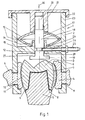
- a device 1 for applying a pull-off force is placed with its housing 2 on a pull-off frame 3 or is formed in one piece.
- the trigger frame 3 carries two holding jaws 4, which are housed in non-contiguous wall parts.
- the trigger frame 3 is open at the front and rear, that is in the direction of extension of the jaw or teeth.
- a tooth stump 5 is shown, on which a crown 6 with a facing 7 is placed and fastened with the aid of a film 8 of fastening cement.
- the holding jaws 4 do not engage in the area of the edge 9 of the crown 6 or the facing 7, but in the area of the lateral surface 10; the holding jaws 4 can each consist of a mass piece made of thermoplastic material, which is stored and held in openings 11 of the trigger frame 3.
- the device 1 In the area of the housing 2, the device 1 has an inwardly projecting edge 12 and a type of intermediate floor 13, in the area of which a plurality of springs 15, which are designed as plate springs, are supported by means of a collar 14.
- a mass projectile 17 in the form of a bolt 18 with a head 19 is mounted such that it can be displaced to a limited extent.
- the bolt 18 has a threaded shaft 20, on which a nut 21 with a corresponding counter thread can be screwed to different extents.
- the nut 21 has a bead 22 which projects beyond the housing 2.
- the housing can carry 2 markings 23, so that depending on how far the nut 21 is screwed onto the threaded shaft 20 and thus the spring 15 is pretensioned, a corresponding display of the pretensioning force is possible with the aid of the markings 23.
- the springs 15 are supported on the intermediate floor 13 and, on the other hand, come into contact with the nut 21, so that the mass projectile 17 is acted upon by this power source in the opposite direction to the insertion direction 16.
- the bolt 18 has a circumferential groove 24, in which a trigger 25 engages with the aid of a slide 26, so that the parts assume the position shown in FIG. 1 under pretension of the springs 15, in which the head 19 of the mass projectile 17 is at a distance 27 occupies from the projecting edge 12.
- the distance 27 corresponds to the possible stroke of the mass projectile 17 when released by the trigger 25 or the slide 26, so that a movement path is thus created opposite the insertion direction 16, at the end of which the head 19 onto the projecting edge 12 in the manner of an anvil 28 hits and thus suddenly transmits its kinetic energy to the intermediate floor 13 and thus to the housing 2, the trigger frame 3 and the holding plates -4.
- the trigger 25 can be designed in the manner of a Bowden cable - can be triggered by train or by pressure.
- the device is handled as follows. To pull off the crown 6, it is first necessary to preheat the holding jaws 4, for example by immersing them in a water bath, so that a plastic state of the thermoplastic holding jaw is achieved in each case. Preheated in this way, the device is then pushed onto the crown 6 in accordance with the direction of insertion 16, the holding jaws 4 coming into contact with each other on the lateral surface 10 and the thermoplastic solidifying to emulate the corresponding shape.
- the trigger 25 is actuated, that is to say the slide 26 is pulled out of the groove 24, so that the force of the springs 15 acts on the mass projectile 17 opposite the insertion direction 16 centrally above the crown 6.
- the ground floor 17 flies upwards until the head 19 suddenly strikes the anvil 28 at the end of the movement path.
- the movement path of the ground floor 17 is thus ended and the kinetic energy of the ground floor 17 is ultimately transmitted to the crown 6 as an abrupt impulse, so that the holding force of the film 8 of the fastening cement is exceeded with a very short exposure time.
- the crown 6 is thus removed from the tooth stump 5 relaxed.
- the force was applied only for a very short time, using a relatively small mass of the mass projectile 17 and acting in the opposite direction to the insertion direction 16, the two holding jaws 4 acting on the crown 6 opposite one another.
- the springs 15 are interchangeable with other springs, i.e. those with a different preload force, if the transmittable impact pulse is to be adapted to changing conditions. This is the case if the area of the one spring 15 that is covered by the markings 23 is not sufficient. It also goes without saying that there is also the possibility of ultimately connecting the nut 21 to the threaded shaft 20 so that it cannot rotate relative to it, so that such a device cannot be adjusted with regard to the applicable force source, but always reproducibly has and delivers the same pretensioning force. Devices can then be manufactured and used with different power sources, which can be selected depending on the application.
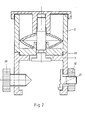
- Fig. 2 shows a device which is in principle very similar, but is divided horizontally, i.e. the housing 2 and the trigger frame 3 do not form a one-piece material part here, but can be connected to one another by means of a thread 29.
- the pull-off frame 3 is designed to be correspondingly wide or long, with different pairs of holding jaws 4 being provided one behind the other.
- These holding jaws 4 can consist of thermoplastic mass pieces (FIG.
- a plug-in connection also offers itself here to the person skilled in the art, for example also in such a way that the trigger frame 3 extends, for example, over the distance of three tooth stumps conceivable side by side, while on the top of such a trigger frame 3 e.g. only two devices 1 can be pushed on, which can be sufficient for a uniform distribution of the pulling force over the length of the trigger frame 3.
- the different variations are indicated.
- the holding jaws 4 can also be varied accordingly, it being possible to provide the openings 11 with a corresponding thread in order to screw in the knurled screws 30 accordingly. It goes without saying that corresponding depressions must be provided on the crown 6 in connection therewith in order to transmit the required pull-off force. However, these depressions are not provided in the area of the edge 9, but also in the area of the lateral surface 10. A shaped piece 31 can also be fixed in the openings 11 with the aid of lock nuts 32 and placed and arranged differently within the opening 16.
- the function of the device according to FIG. 2 corresponds to that according to FIG. 1.
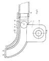
- the trigger frame 3 can be seen here in a side view, the top view of the knurled screw 30 revealing the position of the holding jaws 4 thus realized.
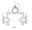
- the housing 2 of the device 1 consists essentially of a pipe-like tube, in which a ball 33 as a mass projectile 17 moves to a limited extent. This movement path corresponding to the curvature of the tube or the housing ends in any case in the opposite direction to the insertion direction 16, the anvil 28 being formed by a web 34 in which one or more openings for the outlet of those displaced by the ball 33 in the housing 2 are displaced Air.
- Compressed air can be directed to the ball 33 via a hose connection 35, for example via a valve (not shown), so that it is accelerated and runs through its curved path of movement and finally releases its kinetic energy onto the web 34. Again, the corresponding energy is suddenly transmitted opposite to the insertion direction 16.
- the end of the pipe-like movement path and thus the web 34 need not or should not necessarily be arranged laterally offset from the axis of the knurled screw 30, but is advantageously arranged above this axis so that the transmitted impact force also lies exactly above the crown 6 to be removed takes effect. A slight offset does not do any harm here since the device is ultimately still held by the operator. This also prevents tilting and damage to the dentures.
- the device can have a second compressed air line 36 in the area of the housing 2, which opens into the path of movement of the ball 33 in the area of the web 34 and thus - understandably with considerably reduced pressure - acts on the return of the ball 33 to its starting position.
- the two compressed air lines can thus be controlled alternately or in another way.
Landscapes
- Health & Medical Sciences (AREA)
- Oral & Maxillofacial Surgery (AREA)
- Dentistry (AREA)
- Epidemiology (AREA)
- Life Sciences & Earth Sciences (AREA)
- Animal Behavior & Ethology (AREA)
- General Health & Medical Sciences (AREA)
- Public Health (AREA)
- Veterinary Medicine (AREA)
- Dental Tools And Instruments Or Auxiliary Dental Instruments (AREA)
Priority Applications (1)
| Application Number | Priority Date | Filing Date | Title |
|---|---|---|---|
| AT85905797T ATE39050T1 (de) | 1985-10-30 | 1985-10-30 | Vorrichtung zum entfernen von kronen, bruecken o. dgl. von zahnstuempfen. |
Applications Claiming Priority (1)
| Application Number | Priority Date | Filing Date | Title |
|---|---|---|---|
| PCT/EP1985/000577 WO1987002573A1 (fr) | 1985-10-30 | 1985-10-30 | Dispositif pour enlever une couronne, un bridge ou analogue d'un chicot dentaire |
Publications (2)
| Publication Number | Publication Date |
|---|---|
| EP0232276A1 EP0232276A1 (de) | 1987-08-19 |
| EP0232276B1 true EP0232276B1 (de) | 1988-12-07 |
Family
ID=8165073
Family Applications (1)
| Application Number | Title | Priority Date | Filing Date |
|---|---|---|---|
| EP85905797A Expired EP0232276B1 (de) | 1985-10-30 | 1985-10-30 | Vorrichtung zum entfernen von kronen, brücken o. dgl. von zahnstümpfen |
Country Status (4)
| Country | Link |
|---|---|
| US (1) | US4725233A (enExample) |
| EP (1) | EP0232276B1 (enExample) |
| JP (1) | JPS63501194A (enExample) |
| WO (1) | WO1987002573A1 (enExample) |
Families Citing this family (11)
| Publication number | Priority date | Publication date | Assignee | Title |
|---|---|---|---|---|
| US4923399A (en) * | 1988-08-22 | 1990-05-08 | Funderburg Jr Issac M | Dental instrument |
| US5669771A (en) * | 1992-02-12 | 1997-09-23 | Lee; Robert L. | Dental restoration holder system |
| US5320533A (en) * | 1992-02-12 | 1994-06-14 | Lee Robert L | Fixed prosthodontic tool kit and method for placing and fitting crowns and inlays |
| US5575649A (en) * | 1992-02-12 | 1996-11-19 | Lee; Robert L. | Dental restoration holder system |
| US5547380A (en) * | 1994-08-19 | 1996-08-20 | Goodman; Jack | Method of using ultrasonic dental tool |
| AU8243698A (en) * | 1998-07-16 | 2000-02-07 | Palm Inc. | Forceps capable of removing fitted crown in reusable form and method of removingthe crown |
| US20040043359A1 (en) * | 2002-08-29 | 2004-03-04 | Gordon Gould | Method for removing a dental crown and apparatus therefor |
| WO2004111064A1 (en) * | 2003-06-16 | 2004-12-23 | Institute Of Organic Chemistry And Biochemistry, Academy Of Sciences Of The Czech Republic | Pyrimidine compounds having phosphonate groups as antiviral nucleotide analogs |
| US20050282110A1 (en) * | 2004-06-17 | 2005-12-22 | Jack Goodman | Method for removing a dental crown and apparatus therefor |
| US8292623B2 (en) * | 2009-05-11 | 2012-10-23 | Jory Brock Vandor | Systems and methods for setting prosthetic posterior teeth in denture production |
| EP3335666B1 (de) * | 2016-12-15 | 2021-03-10 | Ivoclar Vivadent AG | Vorrichtung zum halten einer anordnung aus suprastruktur und abutment |
Family Cites Families (14)
| Publication number | Priority date | Publication date | Assignee | Title |
|---|---|---|---|---|
| US152391A (en) * | 1874-06-23 | Improvement in atmospheric hammers | ||
| US394464A (en) * | 1888-12-11 | Pneumatic dental plugger | ||
| US2337971A (en) * | 1941-10-28 | 1943-12-28 | Caviglia Oscar Luis | Percussion extracting device |
| US2376187A (en) * | 1944-11-13 | 1945-05-15 | Reiter David | Dental mallet |
| US2776490A (en) * | 1955-06-03 | 1957-01-08 | Arthur B Carfagni | Multi-purpose dental tool |
| US2848812A (en) * | 1957-07-10 | 1958-08-26 | Fuest John | Dental pliers |
| US3254412A (en) * | 1963-03-20 | 1966-06-07 | Thomas A Armao | Dental prosthesis extractor device |
| US3553841A (en) * | 1967-10-23 | 1971-01-12 | George K Austin Jr | Amalgam condenser |
| US3690007A (en) * | 1971-08-13 | 1972-09-12 | Arthur Rybeck Jr S | Dental crown and bridge removing adaptor |
| DE2346671A1 (de) * | 1972-09-19 | 1974-04-04 | Toma | Auf pneumatischem wege betriebene auszieh- oder extraktionsvorrichtung, insbesondere zur verwendung in der zahnmedizin oder zahnpflege |
| US3889376A (en) * | 1974-05-06 | 1975-06-17 | Allen M Zatkin | Crown removing device |
| DE2747521A1 (de) * | 1977-10-22 | 1979-04-26 | Guenter Dipl Ing Scheffler | Kronen- und brueckenentferner |
| US4300885A (en) * | 1980-07-30 | 1981-11-17 | George Khait | Percussive dental crown extractor |
| DE3417067C2 (de) * | 1984-05-09 | 1987-04-30 | Jens 3402 Dransfeld Planert | Vorrichtung zum Entfernen von Kronen, Brücken o. dgl. von Zahnstümpfen |
-
1985
- 1985-10-30 EP EP85905797A patent/EP0232276B1/de not_active Expired
- 1985-10-30 US US06/913,675 patent/US4725233A/en not_active Expired - Fee Related
- 1985-10-30 JP JP60505227A patent/JPS63501194A/ja active Granted
- 1985-10-30 WO PCT/EP1985/000577 patent/WO1987002573A1/de not_active Ceased
Also Published As
| Publication number | Publication date |
|---|---|
| EP0232276A1 (de) | 1987-08-19 |
| US4725233A (en) | 1988-02-16 |
| JPS63501194A (ja) | 1988-05-12 |
| WO1987002573A1 (fr) | 1987-05-07 |
| JPH0576307B2 (enExample) | 1993-10-22 |
Similar Documents
| Publication | Publication Date | Title |
|---|---|---|
| DE19505304B4 (de) | Hohler Greifer zur Implantation eines Fadenankers | |
| EP1968502B1 (de) | Chirurgisches werkzeug | |
| EP0232276B1 (de) | Vorrichtung zum entfernen von kronen, brücken o. dgl. von zahnstümpfen | |
| EP1578296B1 (de) | Vorrichtung zur extraktion einer zahnwurzel | |
| DE102005016736A1 (de) | Kieferorthopädische Vorrichtung insbesondere zum Vorverlagern des Unterkiefers eines Patienten | |
| DE2257156B2 (de) | Zahnzange zum extrahieren von zaehnen | |
| DE3242415A1 (de) | Zahnstift und drehmomentschluessel fuer denselben sowie verfahren zum fuellen einer zahnwurzel mittels derselben | |
| EP1411853B1 (de) | Vorrichtung zum entfernen von zähnen | |
| DE3417067C2 (de) | Vorrichtung zum Entfernen von Kronen, Brücken o. dgl. von Zahnstümpfen | |
| DE29807671U1 (de) | Chirurgisches Instrument | |
| DE60111492T2 (de) | Kronenheber | |
| DE19646097C2 (de) | Einrichtung zur Kraftaufbringung und Krafteinleitung auf zu extrahierende Zähne | |
| WO2010139459A1 (de) | Zahnärztliche zange | |
| DE10240683B4 (de) | Zahnärztlicher Matrizenspanner | |
| DE4219411C1 (de) | Einsetzwerkzeug für eine Schraubeneinheit | |
| DE3718026A1 (de) | Vorrichtung zum befestigen eines bohrwerkzeuges an einem zahnaerztlichen instrument mit einer vibrationsbewegung | |
| EP1639960B1 (de) | Vorrichtung zur Entfernung von Zahnapplikationen wie Brackets | |
| WO2001054607A1 (de) | Osteotomie-vorrichtung zur schaffung von implantat-kavitäten durch aufweitung des kieferknochens | |
| DE2412113C3 (de) | Zahnzange zum Extrahieren von Zähnen | |
| DE3621055C2 (enExample) | ||
| EP2777885B1 (de) | Vorrichtung zum Lösen einer im Mauerwerk, Beton oder dergleichen festsitzenden Bohrkrone | |
| DE19500818C1 (de) | Zange zum Erfassen und Entfernen von Kronen auf bzw. von Zahnstümpfen | |
| DE10140061C2 (de) | Knochenspaltwerkzeug | |
| DE2502036A1 (de) | Befestigungsvorrichtung fuer totalprothesen | |
| EP0574658A1 (de) | Einsetzwerkzeug für eine Schraubenezahnprothese |
Legal Events
| Date | Code | Title | Description |
|---|---|---|---|
| PUAI | Public reference made under article 153(3) epc to a published international application that has entered the european phase |
Free format text: ORIGINAL CODE: 0009012 |
|
| AK | Designated contracting states |
Kind code of ref document: A1 Designated state(s): AT FR |
|
| 17P | Request for examination filed |
Effective date: 19870716 |
|
| 17Q | First examination report despatched |
Effective date: 19871026 |
|
| GRAA | (expected) grant |
Free format text: ORIGINAL CODE: 0009210 |
|
| AK | Designated contracting states |
Kind code of ref document: B1 Designated state(s): AT FR |
|
| REF | Corresponds to: |
Ref document number: 39050 Country of ref document: AT Date of ref document: 19881215 Kind code of ref document: T |
|
| ET | Fr: translation filed | ||
| PLBE | No opposition filed within time limit |
Free format text: ORIGINAL CODE: 0009261 |
|
| STAA | Information on the status of an ep patent application or granted ep patent |
Free format text: STATUS: NO OPPOSITION FILED WITHIN TIME LIMIT |
|
| 26N | No opposition filed | ||
| PGFP | Annual fee paid to national office [announced via postgrant information from national office to epo] |
Ref country code: FR Payment date: 20041019 Year of fee payment: 20 |
|
| PGFP | Annual fee paid to national office [announced via postgrant information from national office to epo] |
Ref country code: AT Payment date: 20041022 Year of fee payment: 20 |