EP0229633A2 - Verfahren und Vorrichtung zur chemischen Bedampfung unter Verwendung eines Lasers - Google Patents
Verfahren und Vorrichtung zur chemischen Bedampfung unter Verwendung eines Lasers Download PDFInfo
- Publication number
- EP0229633A2 EP0229633A2 EP87100120A EP87100120A EP0229633A2 EP 0229633 A2 EP0229633 A2 EP 0229633A2 EP 87100120 A EP87100120 A EP 87100120A EP 87100120 A EP87100120 A EP 87100120A EP 0229633 A2 EP0229633 A2 EP 0229633A2
- Authority
- EP
- European Patent Office
- Prior art keywords
- chamber
- substrates
- energy beam
- gases
- energy
- Prior art date
- Legal status (The legal status is an assumption and is not a legal conclusion. Google has not performed a legal analysis and makes no representation as to the accuracy of the status listed.)
- Withdrawn
Links
- 238000000034 method Methods 0.000 title description 15
- 238000001182 laser chemical vapour deposition Methods 0.000 title description 2
- 239000000758 substrate Substances 0.000 claims abstract description 188
- 239000007789 gas Substances 0.000 claims abstract description 101
- 239000000126 substance Substances 0.000 claims abstract description 82
- 230000003472 neutralizing effect Effects 0.000 claims abstract description 22
- 230000001427 coherent effect Effects 0.000 claims abstract description 13
- 239000000203 mixture Substances 0.000 claims abstract description 10
- 238000000151 deposition Methods 0.000 claims description 40
- 230000008021 deposition Effects 0.000 claims description 34
- 230000000750 progressive effect Effects 0.000 claims description 21
- 230000003313 weakening effect Effects 0.000 claims description 9
- 230000015572 biosynthetic process Effects 0.000 claims description 7
- 230000001105 regulatory effect Effects 0.000 claims 6
- 230000001276 controlling effect Effects 0.000 claims 3
- 230000001154 acute effect Effects 0.000 claims 1
- 238000010438 heat treatment Methods 0.000 claims 1
- 230000007423 decrease Effects 0.000 abstract description 6
- VYPSYNLAJGMNEJ-UHFFFAOYSA-N Silicium dioxide Chemical compound O=[Si]=O VYPSYNLAJGMNEJ-UHFFFAOYSA-N 0.000 description 14
- IJGRMHOSHXDMSA-UHFFFAOYSA-N Atomic nitrogen Chemical compound N#N IJGRMHOSHXDMSA-UHFFFAOYSA-N 0.000 description 10
- GQPLMRYTRLFLPF-UHFFFAOYSA-N Nitrous Oxide Chemical compound [O-][N+]#N GQPLMRYTRLFLPF-UHFFFAOYSA-N 0.000 description 8
- 235000012239 silicon dioxide Nutrition 0.000 description 7
- 239000000377 silicon dioxide Substances 0.000 description 7
- 239000000463 material Substances 0.000 description 5
- 229910052757 nitrogen Inorganic materials 0.000 description 5
- 230000000694 effects Effects 0.000 description 4
- 239000001272 nitrous oxide Substances 0.000 description 4
- 230000002401 inhibitory effect Effects 0.000 description 3
- 230000002829 reductive effect Effects 0.000 description 3
- 235000012431 wafers Nutrition 0.000 description 3
- BLRPTPMANUNPDV-UHFFFAOYSA-N Silane Chemical compound [SiH4] BLRPTPMANUNPDV-UHFFFAOYSA-N 0.000 description 2
- XUIMIQQOPSSXEZ-UHFFFAOYSA-N Silicon Chemical compound [Si] XUIMIQQOPSSXEZ-UHFFFAOYSA-N 0.000 description 2
- 239000002253 acid Substances 0.000 description 2
- XAGFODPZIPBFFR-UHFFFAOYSA-N aluminium Chemical compound [Al] XAGFODPZIPBFFR-UHFFFAOYSA-N 0.000 description 2
- 229910052782 aluminium Inorganic materials 0.000 description 2
- 230000003247 decreasing effect Effects 0.000 description 2
- 238000004519 manufacturing process Methods 0.000 description 2
- 230000005855 radiation Effects 0.000 description 2
- 229910000077 silane Inorganic materials 0.000 description 2
- 229910052710 silicon Inorganic materials 0.000 description 2
- 239000010703 silicon Substances 0.000 description 2
- 150000007513 acids Chemical class 0.000 description 1
- QVGXLLKOCUKJST-UHFFFAOYSA-N atomic oxygen Chemical compound [O] QVGXLLKOCUKJST-UHFFFAOYSA-N 0.000 description 1
- 238000005229 chemical vapour deposition Methods 0.000 description 1
- 230000003749 cleanliness Effects 0.000 description 1
- 230000002939 deleterious effect Effects 0.000 description 1
- 230000001419 dependent effect Effects 0.000 description 1
- 238000010292 electrical insulation Methods 0.000 description 1
- 230000002708 enhancing effect Effects 0.000 description 1
- 239000012535 impurity Substances 0.000 description 1
- 150000002500 ions Chemical class 0.000 description 1
- 230000000670 limiting effect Effects 0.000 description 1
- QSHDDOUJBYECFT-UHFFFAOYSA-N mercury Chemical compound [Hg] QSHDDOUJBYECFT-UHFFFAOYSA-N 0.000 description 1
- 229910052753 mercury Inorganic materials 0.000 description 1
- 238000012544 monitoring process Methods 0.000 description 1
- 239000001301 oxygen Substances 0.000 description 1
- 229910052760 oxygen Inorganic materials 0.000 description 1
- 230000002093 peripheral effect Effects 0.000 description 1
- 230000000644 propagated effect Effects 0.000 description 1
- 238000007493 shaping process Methods 0.000 description 1
- 229910052724 xenon Inorganic materials 0.000 description 1
- FHNFHKCVQCLJFQ-UHFFFAOYSA-N xenon atom Chemical compound [Xe] FHNFHKCVQCLJFQ-UHFFFAOYSA-N 0.000 description 1
Images


Classifications
-
- H—ELECTRICITY
- H01—ELECTRIC ELEMENTS
- H01L—SEMICONDUCTOR DEVICES NOT COVERED BY CLASS H10
- H01L21/00—Processes or apparatus adapted for the manufacture or treatment of semiconductor or solid state devices or of parts thereof
-
- C—CHEMISTRY; METALLURGY
- C23—COATING METALLIC MATERIAL; COATING MATERIAL WITH METALLIC MATERIAL; CHEMICAL SURFACE TREATMENT; DIFFUSION TREATMENT OF METALLIC MATERIAL; COATING BY VACUUM EVAPORATION, BY SPUTTERING, BY ION IMPLANTATION OR BY CHEMICAL VAPOUR DEPOSITION, IN GENERAL; INHIBITING CORROSION OF METALLIC MATERIAL OR INCRUSTATION IN GENERAL
- C23C—COATING METALLIC MATERIAL; COATING MATERIAL WITH METALLIC MATERIAL; SURFACE TREATMENT OF METALLIC MATERIAL BY DIFFUSION INTO THE SURFACE, BY CHEMICAL CONVERSION OR SUBSTITUTION; COATING BY VACUUM EVAPORATION, BY SPUTTERING, BY ION IMPLANTATION OR BY CHEMICAL VAPOUR DEPOSITION, IN GENERAL
- C23C16/00—Chemical coating by decomposition of gaseous compounds, without leaving reaction products of surface material in the coating, i.e. chemical vapour deposition [CVD] processes
- C23C16/44—Chemical coating by decomposition of gaseous compounds, without leaving reaction products of surface material in the coating, i.e. chemical vapour deposition [CVD] processes characterised by the method of coating
- C23C16/48—Chemical coating by decomposition of gaseous compounds, without leaving reaction products of surface material in the coating, i.e. chemical vapour deposition [CVD] processes characterised by the method of coating by irradiation, e.g. photolysis, radiolysis, particle radiation
- C23C16/483—Chemical coating by decomposition of gaseous compounds, without leaving reaction products of surface material in the coating, i.e. chemical vapour deposition [CVD] processes characterised by the method of coating by irradiation, e.g. photolysis, radiolysis, particle radiation using coherent light, UV to IR, e.g. lasers
Definitions
- This invention relates to apparatus for, and methods of, producing a substantially uniform, pure and stable deposition of a substance on a substrate.
- the invention particularly relates to apparatus for, and methods of, providing an energy beam to produce a substantially uniform, pure and stable deposition of a substance on a substrate, or aligned substrates, in a chamber even though the strength of the energy beam may vary at progressive positions along the substrate or substrates in the chamber.
- substrates or wafers made from a suitable material are provided. Successive layers of materials are then deposited on the substrates. For example, layers of silicon dioxide may be deposited on the substrates to provide electrical insulation and layers of aluminum may be deposited on the surface to provide electrical continuity. Suitable materials such as acids may then be applied to the substrates in patterns to etch the aluminum on the substrates and thereby produce electrical circuits.
- ionizable gases may be introduced into a chamber.
- An energy beam may then be introduced into the chamber to ionize the gases.
- the ionized gases may then combine to form the substance, which becomes deposited on the substrates in the chamber.
- the substance thus produced may be a suitable gas such as silicon dioxide which becomes deposited on the substrates or the substance may be a suitable material such as an acid which etches layers previously deposited on the substrate.
- apparatus and methods have been developed, and are in use, for depositing a substance on a substrate by techniques of chemical vapor deposition. Some of such apparatus and methods even provide for a deposition of the substance on the substrate at low temperatures. Such apparatus and methods are also disadvantageous because they do not produce a substantially uniform, pure and stable deposition of the substance on the substrate.
- Heat is directed on a localized basis to the substrates in a direction substantially perpendicular to the substrates to facilitate the deposition of the substance on the substrates.
- the substrate can be adjusted in position relative to the light beam to optimize the deposition of the substance on the substrate.
- the substance deposited on the substrates can constitute an additional layer on the substrates or it can etch a layer previously deposited on the substrates.
- the apparatus of co-pending application Serial No. 587,284 is further advantageous in that it maximizes the cleanliness of the deposit on the substrates by limiting the deposition only to the substrates and inhibiting the deposition of the substances on the walls of the chamber.
- the invention of co-pending applicaiton Serial No. 587,284 is further advantageous in that no radiation damage is produced on the substrate by the use of laser techniques and by the direction of the laser in a direction substantially parallel to the substrates.
- This invention provides a number of improvements in the apparatus and methods disclosed and claimed in application Serial No. 587,284. Such improvements are designed to enhance the uniformity, purity and stability of the substance deposited on the substrates in a chamber by compensating for the progressive weakening of the energy beam as the energy beam moves along the substrates. Such improvements are further designed to enhance the efficiency in the operation of such apparatus and in such methods from several different standpoints in addition to enhancing the uniformity, stability and purity of the substance deposited on the substrates in the chamber. These include the number of substrates capable of receiving a deposition of the substance at any one time and the rate at which the substance can be deposited uniformly on such substrates.
- a beam of substantially coherent light passes through a window in a chamber and then through the chamber in a direction substantially parallel, and contiguous, to a substrate (or substrates) in the chamber.
- the beam ionizes gases in a mixture in the chamber.
- the ionized gases combine to form a substance which becomes deposited on the substrate(s) to form a layer on the substrate(s) in the chamber or which etches a previously deposited layer on the substrates.
- the beam moves through the chamber, it loses energy.
- Various individual, or combinations of, compensations for the loss of energy in the beam may include: (l) the substrate(s) may be tilted slightly in the chamber to decrease the distance between the beam and the substrate(s) as the beam moves through the chamber; (2) the beam may be tapered in a direction along the substrate(s); (3) the rate and direction of the flow of a mixture of ionizable gases through the chamber may be adjusted; (4) the rate and direction of flow of a gas for neutralizing the ionization of the gases in the mixture may be adjusted; (5) the rate of flow of the gases in the mixture may be individually adjusted for each of the substrates in the chamber; and (6) the rate and direction of flow of the neutralizing gas may be individually adjusted for each of the substrates in the chamber. Lenses may be included in the window for producing the desired configuration of the energy beam.
- the chamber may be disposed within a compartment.
- a first portion of the energy beam may be directed through the chamber.
- a second portion of the beam may be directed through the compartment area external to the chamber and may then be redirected to pass through the chamber in a direction opposite to the first portion and at positions substantially parallel, and contiguous, to the substrate(s) in the chamber.
- a member generally indicated at l0 is provided for producing a beam of substantially coherent light, preferably in the ultraviolet range.
- beam of substantially coherent light is used advisedly since it may not be advantageous to have the light completely coherent. One reason is that completely coherent light may establish standing waves along the substrate and these standing waves may inhibit a uniform deposition of the substance on the substrate.
- the member l0 may be a commercially available laser such as a Lumonics 850T Excimer laser.
- the laser beam may be pulsed at a suitable repetition rate such as l00 hertz and may be operated on the l93nm ArF line.
- the laser beam may be directed through lenses ll toward substrates l2, such as integrated circuit wafers, in a chamber 18.
- substrates l2 such as integrated circuit wafers
- Each of the substrates may be provided with a flat periphery l2a ( Figure 12) to facilitate a precise positioning of the substrate on a support plate l4 in the chamber 18.
- Each support plate l4 may define the periphery of a window l6 in the chamber l8.
- the light from the laser l0 may be directed to a beam splitter l5 which transmits most of the light incident upon it and reflects a selected portion, which may be ten percent (l0%) to fifteen percent (l5%), to a photodetector l7.
- the output of the photodetector l7 is proportional to the power of the beam from the laser l0 and is introduced to a power meter l9 for monitoring the power output from the laser l0.
- the beam of substantially coherent light is preferably shaped before it is directed to the substrate(s) l2. This shaping is preferably accomplished by the lenses 11 to produce a light beam 28 which is substantally parallel, and contiguous, to the substrates l2 in the chamber 18 and which is as wide as the lateral dimension of each of the substrates.
- the lenses 11 may be provided with a suitable configuration to widen the beam in the lateral dimension.
- each substrate l2 is substantially flush with the surface of the supporting plate l4.
- the gases moving past the substrates l2 in the chamber 18 have a substantially uniform flow rather than being subjected to turbulence such as tends to occur when the surface to be coated on the substrates 12 is not substantially flush with the surface of the plates 14.
- a nozzle 30 is disposed in the chamber l8 preferably in contiguous relationship to the substrate l2 at one end of the chamber.
- the nozzle 30 is disposed at the far end of the chamber l8 in the direction of passage of the light beam 28 through the chamber.
- the nozzle 30 may be disposed at the near end of the chamber in the direction of movement of the light beam 28.
- the nozzle 30 is preferably disposed at substantially the same vertical level as the top surfaces of the substrates l2 in the chamber l8 and is adapted to introduce ionizable gases under pressure in a direction substantially parallel to the substrates.
- the nozzle 30 is adapted to introduce a mixture of ionizable gases which react to form the substance when energized at a relatively high energy level such as by the light beam 28.
- the gases may be a silicon donor such as silane (SiH4) in nitrogen and an oxygen donor such as nitrous oxide (N2O).
- the gas such as silane in nitrogen may be obtained from a source 29 and the gas such as nitrous oxide may be obtained from source 3l and these gases may be mixed in the nozzle 30.
- An orifice 32 is also disposed in the chamber l8, preferably in contiguous relationship to the substrates l2 at a second end of the chamber opposite the nozzle 30.
- the orifice 32 is preferably disposed at substantially the same vertical level as the top surfaces of the substrates l2 in the chamber l8.
- the nozzle 30 and the orifice 32 in Figure l are displaced from each other in the direction of the light beam 28, it will be appreciated that the nozzle and the orifice may be disposed in a direction transverse to that shown in Figure l.
- the inlet nozzle 30 may be disposed at one lateral end of the chamber l8 and the orifice 32 may be disposed at the opposite lateral end of the chamber.
- the beam 28 of substantially coherent light When the beam 28 of substantially coherent light is directed through the chamber l8 toward the substrates l2, it energizes molecules of the donor gases introduced into the chamber through the nozzle 30. This causes the donor gases to form the substance (such as silicon dioxide) which becomes deposited on the subtrates l2.
- the substance such as silicon dioxide
- the substrates l2 may be moved relative to the light beam 28.
- the substrates l2 may be moved relative to the light beam in a direction indicated in a direction into and out of the plane of the drawings, particularly when the light beam is not as wide as the substrates. This direction is perpendicular to the direction in which the light beam 28 moves along the substrates l2.
- the substrates l2 may be also rotated relative to the light beam 28 to insure that the substance will be uniformly deposited on the substrates.
- the substrates l2 may be incrementally rotated through successive angles of approximately 90° or through any other angle. The incremental rotation of the substrates l2 may be accomplished while the light beam is being directed over the substrates or may be provided alternately with the direction of pulsated energy from the light beam 28 toward the substrates.
- the chamber l8 may be moved. Preferably this movement is transverse to the direction of the light beam 28. However, this movement may occur in the direction of the light beam or opposite the direction of the light beam.
- the light beam 28 may be reciprocated in the transverse direction to control the deposition of the substance on the substrates. The reciprocation of the light beam 28 may be provided by directing the light from the beam splitter l5 to a mirror substantially parallel to the beam splitter l5 and by reciprocating the mirror in a direction toward and away from the beam splitter l5.
- Energy may be directed to the substrates in a direction substantially perpendicular to the substrates to facilitate the ionization of the donor gases and the formation of the substance and the deposition of the substance on the substrates.
- This energy may be provided by a mercury light source or a xenon flashlamp, both being indicated schematically at 38 in Figure 13.
- the light from the source 38 is directed to a parabolic reflector 39 which directs the beam substantially uniformly only to the surfaces of the substrates 12 in the chamber 18. In this way, the light is effective only on the substrates, thereby minimizing any tendency for the substance to become deposited on the walls of the chamber 18 between the substrates.
- the disposition of each substrate 12 relative to the light beam 28 may be individually provided by adjusting threaded rods 41 relative to nuts 43 in Figure 13.
- the light beam 28 may lose energy. This may result in part when the light beam energizes the molecules of the donor gases to disassociate such molecules for the production of the substance from such disassociated molecules. This loss of energy may prevent the substance from being uniformly deposited on the substrates 12 in the chamber 18. Compensations may be provided in other parameters for the loss of energy in the beam so that the substance will be deposited at a substantially constant rate on all of the substrates 12 in the chamber l8. These different compensations in such other parameters will be discussed in detail subsequently and are included in different embodiments of the invention.
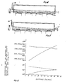
- One form of compensation is to dispose the substrates 12 at a slightly inclined angle such as approximately five degrees (5°) relative to the light beam 28 as shown in Figure 1.
- Each of the substrates 12 is disposed at this angle along a ramp also inclined at this angle of approximately 5°. This causes the distance between the light beam 28 and the substrates 12 to decrease progressively with progressive movement of the light beam 28 through the chamber 18. In this way, any loss of energy in the light beam 28 at progressive positions along the beam in the chamber 18 is compensated by the reduced distance of the beam from the substrates. This causes the energy needed to deposit the substance on the substrates 12 to become correspondingly reduced.
- the loss of energy in the light beam 28 at progressive positions along the substrates 12 may also be compensated by varying the intensity of the beam at different positions in a direction suhstantially perpendicular to the direction in which the beam is propagated in Figure 2.
- This perpendicular direction corresponds to the perpendicular direction in Figure 2.
- the intensity of the light beam 28 is at a maximum at the axial center 40 of the beam.
- the intensity of the light beam 28 decreases progressively with progressive distances from the axial center of the light beam. This is indicated at 42 in Figure 2.
- the slope of the intensity curve in the area 42 of progressively decreasing intensity corresponds to the slope at which the substrates 12 are disposed in the chamber 18. This causes the intensity of the light beam 28 to remain substantially constant relative to the substrates 12 as the light beam moves through the chamber 18. As a result, the rate of deposition of the substance on the substrates 12 is substantially constant regardless of the relative positioning of the substrates in the chamber.
- Figure 3 illustrates another embodiment for compensating for the progressive weakening in the intensity of the light beam 28 as the beam passes through the chamber 18.
- a beam generally indicated at 44 is tapered.
- the taper of the beam may correspond to the rate at which the intensity of the energy beam decreases as the beam passes through the chamber 18.
- the beam 44 By tapering the beam 44, the beam tends to become progressively concentrated adjacent the surfaces of the substrates 12. This enhances the ionization of the gases at positions adjacent the substrates 12, the combination of the ions to form the substance and the deposition of the substance on the surfaces of the substrates.
- the taper of the beam 44 has been varied dependent upon the rate at which the beam has become weakened as it has traversed the chamber 18. For example, the taper has been varied in some instances from a height of approximately seven millimeters (7 mm) at the front end of the chamber 18 to approximately six millimeters (6 mm) at the rear end of the chamber. In other instances, the taper of the beam 44 has been varied from a height of approximately seven millimeters (7 mm) at the front end of the chamber 18 to approximately two millimeters (2 mm) at the rear end of the chamber.
- the direction and the rate of flow of the ionizable gases can also be varied to compensate for the progressive weakening of the energy beam as the beam moves through the chamber 18.
- the taper of the energy beam varies only from a height of approximately seven millimeters (7mm) at the front end of the chamber to approximately six millimeters (6 mm) at the rear end of the chamber, this may not be sufficient in itself to compensate for the progressive weakening in the intensity of the beam. Additional compensation may accordingly be provided by obtaining a controlled flow of ionizable gases from the front end of the chamber 18 to the rear end of the chamber. This is indicated by an arrow 48 in Figure 4.
- the gases ionized near the front end of the chamber continue to move toward the rear end of the chamber after ionization and to form the substance toward the rear of the chamber.
- This causes the substance to become deposited on the substrates at the rear end of the chamber at a greater rate than at the front end of the chamber, thereby compensating for the increased intensity of the beam at the front end of the chamber relative to the intensity of the beam at the rear end of the chamber.
- the rate of flow of the gases can be controlled to assure that the substance becomes substantially uniformly deposited on the substrates 12.
- Figure 5 also shows an embodiment in which the direction and rate of a neutralizing gas can be controlled to achieve a substantially uniform deposition of the substance on the substrates 12.
- the neutralizing gas is directed from the front of the chamber toward the rear of the chamber through a nozzle 46 and is withdrawn from the chamber through an orifice 47 at the front of the chamber.
- the neutralizing gases accordingly have their optimal effect at the front of the chamber in inhibiting the ionization of the ionizable gases, the formation of the substance from the ionized gases and the deposition of the substance on the substrates 12 in the chamber 18.
- Compensations may also be provided in the direction and rate of gas flows in the chamber 18 when the height of the light beam 28 is tapered from approximately seven millimeters (7 mm) at the front end of the chamber to approximately two millimeters (2 mm) at the rear end of the chamber.
- the ionizing gases may be directed from the rear end of the chamber 18 toward the front end of the chamber and may be exhausted from the front end of the chamber because of the concentration of the light beam at the rear end of the chamber.
- the ionized gases move toward the front end of the chamber before they react to form the substance, which then becomes deposited on the substrates 12. In this way, more of the substance tends to become deposited on the substrate 12 toward the front end of the chamber than toward the rear end of the chamber, thereby compensating for the increased concentration of the light beam toward the rear end of the chamber.
- the neutralizing gas such as nitrogen may be passed through the chamber from the rear end of the chamber to the front end of the chamber. This causes the neutralizing gas to have a greater effect at the rear end of the chamber in inhibiting the ionization of the ionizable gases than at the front end of the chamber. This compensates for the considerably increased strength of the light beam 28 at the rear end of the chamber 18 than at the front end of the chamber.
- Figure 6 illustrates the effect of different parameters on the rate at which the substance is deposited on the substrates at different positions in the chamber 18.
- the rate of deposition of the substance on the substrates 12 is substantially constant for two (2) of the examples shown in Figure 6. These are represented by (1) a magnitude of approximately twenty (20) watts from the light beam 28 and a rate of flow of ionizable gases of approximately forty five centimeters per second (45 cm/sec) and (2) a magnitude of approximately fifteen (15) watts for the light beam 28 and a rate of flow of ionizable gases of approximately twenty five centimeters per second (25 cm/sec).
- the substance such as silicon dioxide becomes deposited on the substrates 12 in the chamber 18 at a rate of approximately twelve hundred angstrom per minute (1200 A°/min).
- the substance such as silicon dioxide becomes deposited on the substrates 12 in the chamber 18 at a rate of approximately seven hundred and fifty angstroms per minute (750 A°/min).
- gases are passed through the chamber 18 either in the direction of the light beam 28 or in a direction opposite to the direction of the light beam 28.
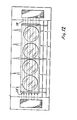
- Figure 7 illustrates an arrangement in which the ionizable gases are passed through the chamber 18 in a direction transverse (preferably perpendicular) to the direction of the light beam 28.
- the ionizable gases may be introduced into the chamber 18 through inlets such as inlets 60a, 60b, 60c and 60d and may be exhausted from the chamber 18 through outlets such as outlets 62a, 62b, 62c and 62d.
- the inlet 60a and the outlet 62a may be disposed adjacent a first one of the substrates 12 in the chamber 18 and the successive pairs of the inlets and outlets may be disposed adjacent progressive ones of the substrates 12 in the chamber 18.
- the rate of flow through each of the inlets can be individually adjusted to compensate for the progressive weakening in the strength of the light beam 28 as the light beam moves through the chamber 18.
- the successive ones of the inlets 60a, 60b, 60c and 60d may be progressively opened to provide an increased rate of flow of the ionizable gases past each of the successive substrates 12 in the chamber 18. This compensates for the progressive loss in the intensity of the beam energy as the beam 28 moves through the chamber 18.
- Figure 8 indicates the distance in the chamber 18 along the horizontal axis and the rate of deposition of the substance on the substrates 12 at these progressive distances.
- the rate of deposition of the substance on the substrates 12 is substantially constant at progressive positions in the chamber 18 even though the intensity of the light beam 28 decreases at such progressive positions and the pressure (or rate of flow) of an ionizable gas such as nitrous oxide increases at such progressive positions.
- the outlets 62a, 62b, 62c and 62d may be controlled to affect the rates at which the ionizable gas is exhausted from the chamber 18 by each individual one of such oulets.
- Figure 9 is a view similar to that shown in Figure 8.
- a neutralizing gas such as nitrogen is introduced into the chamber 18 through inlets such as inlets 70a, 70b, 70c and 70d and is exhausted from the chamber through outlets such as outlets 72a, 72b, 72c and 72d.
- the rate of flow of the neutralizing gas is progressively reduced through each of the successive inlets 70a, 70b, 70c and 70d.
- the outlets 72a, 72b, 72c and 72d may be controlled to affect the rate at which the neutralizing gas is exhausted from the chamber 18 by each individual one of such outlets.
- the neutralizing gas effectively dilutes the ionizable gases.
- the embodiment shown in Figure 9 can be considered to be the inverse of the embodiment shown in Figure 7 since the effect of the ionizable gases in the embodiment of Figure 9 is effectively increased at progressive positions in the chamber 18 by decreasing the amount of the neutralizing gas at these progressive positions. It will be appreciated, however, that the embodiments shown in Figures 7 and 9 can be combined into a single operative unit.
- Figure 10 illustrates another arrangement for compensating for the loss of energy in the light beam 28 as the light beam traverses the chamber 18.
- the light beam 28 is wider than the lateral width of the chamber 18.
- the light beam 28 has peripheral portions 28a which are outside of the lateral dimensions of the chamber 18.
- Lenses 80 are disposed to intercept the beam portions 28a and to focus the light in these beam portions.
- the focussed beam portions 28a then move along the chamber 18 in areas 74 outside of, but adjacent, the chamber.
- the areas 74 are provided with a vacuum which are filled with a neutralizing gas such as nitrogen.
- the beam portions 28a then become reflected by mirrors 84 and 86 to enter the chamber at the far end of the chamber.
- the beam portions 28a then pass through the chamber 18 in a direction opposite to the direction of the main portion of the beam 28.
- the beam portions 28a may be controlled so that their combined intensities are substantially equal to the main portion of the beam. In this way, the averaged intensity of the light beam at every position in the chamber 18 is substantially constant.
- any one of the compensating arrangements shown in the previous Figures and described above may be included in the embodiment shown in Figure 10.
- FIG 11 illustrates another embodiment of the invention.
- lenses 90 are disposed in a window 92 to focus the light beam 28 as the light beam passes through the window into the chamber 18.
- the lenses 90 may be included in the window 92 to taper the light beam 28 in a manner similar to that discussed above and shown in Figure 3.
- the lenses 90 may also be provided with properties to converge the light beam 28 to the lateral width of the chamber 18.
- the focussing of the beam 28 can be provided at the front end of the chamber 18 rather than at positions before the chamber.
- any individual one or combination of the compensating arrangements shown in the previous Figures and described above may be included in the embodiment shown in Figure 11.
- Figure 12 illustrates an additional embodiment of the invention.
- the embodiment shown in Figure 12 includes the light beam 28. This is shown as being directed into the chamber from the left end of the chamber.
- a beam 98 is directed into the chamber 18 from the end of the chamber 18 opposite to that of the beam 28.
- the beam 98 is provided with characteristics suhstantially identical to those of the beam 18. In this way, the two beams are averaged to produce a substantial uniform intensity relative to every position on the substrates in the chamber.
Landscapes
- Chemical & Material Sciences (AREA)
- Engineering & Computer Science (AREA)
- Physics & Mathematics (AREA)
- Metallurgy (AREA)
- Toxicology (AREA)
- General Chemical & Material Sciences (AREA)
- Chemical Kinetics & Catalysis (AREA)
- Health & Medical Sciences (AREA)
- Materials Engineering (AREA)
- Mechanical Engineering (AREA)
- Optics & Photonics (AREA)
- Organic Chemistry (AREA)
- Condensed Matter Physics & Semiconductors (AREA)
- General Physics & Mathematics (AREA)
- Manufacturing & Machinery (AREA)
- Computer Hardware Design (AREA)
- Microelectronics & Electronic Packaging (AREA)
- Power Engineering (AREA)
- Physical Vapour Deposition (AREA)
- Chemical Vapour Deposition (AREA)
Applications Claiming Priority (2)
| Application Number | Priority Date | Filing Date | Title |
|---|---|---|---|
| US06/817,072 US4782787A (en) | 1986-01-08 | 1986-01-08 | Apparatus for laser-induced chemical vapor deposition |
| US817072 | 1986-01-08 |
Publications (2)
| Publication Number | Publication Date |
|---|---|
| EP0229633A2 true EP0229633A2 (de) | 1987-07-22 |
| EP0229633A3 EP0229633A3 (de) | 1988-09-14 |
Family
ID=25222291
Family Applications (1)
| Application Number | Title | Priority Date | Filing Date |
|---|---|---|---|
| EP87100120A Withdrawn EP0229633A3 (de) | 1986-01-08 | 1987-01-07 | Verfahren und Vorrichtung zur chemischen Bedampfung unter Verwendung eines Lasers |
Country Status (4)
| Country | Link |
|---|---|
| US (1) | US4782787A (de) |
| EP (1) | EP0229633A3 (de) |
| JP (1) | JPS62218571A (de) |
| KR (1) | KR870007559A (de) |
Cited By (5)
| Publication number | Priority date | Publication date | Assignee | Title |
|---|---|---|---|---|
| GB2212819A (en) * | 1987-11-30 | 1989-08-02 | Gen Electric | Laser chemical vapor deposition |
| EP0319021A3 (en) * | 1987-12-04 | 1990-04-11 | Fujitsu Limited | Laser chemical vapour deposition method for manufacturing a semiconductor device |
| GB2234529A (en) * | 1989-07-26 | 1991-02-06 | Stc Plc | Epitaxial growth process |
| WO1991002107A1 (en) * | 1989-08-07 | 1991-02-21 | Magyar Tudományos Akadémia Központi Fizikai Kutató Intézete | Method for laser induced chemical vapor deposition on a substrate |
| GB2250751A (en) * | 1990-08-24 | 1992-06-17 | Kawasaki Heavy Ind Ltd | Process for the production of dielectric thin films; pyroelectric sensor |
Families Citing this family (8)
| Publication number | Priority date | Publication date | Assignee | Title |
|---|---|---|---|---|
| US5451550A (en) | 1991-02-20 | 1995-09-19 | Texas Instruments Incorporated | Method of laser CVD seal a die edge |
| JP3505010B2 (ja) * | 1995-07-07 | 2004-03-08 | 本田技研工業株式会社 | 燃料電池およびその締付方法 |
| US7763327B2 (en) * | 1996-04-22 | 2010-07-27 | Micron Technology, Inc. | Methods using ozone for CVD deposited films |
| US7575784B1 (en) | 2000-10-17 | 2009-08-18 | Nanogram Corporation | Coating formation by reactive deposition |
| CA2425838A1 (en) * | 2000-10-17 | 2002-04-25 | Ronald J. Mosso | Coating formation by reactive deposition |
| US8865271B2 (en) * | 2003-06-06 | 2014-10-21 | Neophotonics Corporation | High rate deposition for the formation of high quality optical coatings |
| US7521097B2 (en) * | 2003-06-06 | 2009-04-21 | Nanogram Corporation | Reactive deposition for electrochemical cell production |
| US7491431B2 (en) * | 2004-12-20 | 2009-02-17 | Nanogram Corporation | Dense coating formation by reactive deposition |
Family Cites Families (7)
| Publication number | Priority date | Publication date | Assignee | Title |
|---|---|---|---|---|
| JPS537171A (en) * | 1976-07-09 | 1978-01-23 | Mitsubishi Electric Corp | Vapor phase growth apparatus |
| US4579750A (en) * | 1980-07-07 | 1986-04-01 | Massachusetts Institute Of Technology | Laser heated CVD process |
| JPS5932122A (ja) * | 1982-08-16 | 1984-02-21 | Hitachi Ltd | 表面改質装置 |
| FR2548218B1 (fr) * | 1983-06-29 | 1987-03-06 | Pauleau Yves | Procede de depot de couches minces par reaction chimique en phase gazeuse utilisant deux rayonnements differents |
| JPS59140368A (ja) * | 1983-12-27 | 1984-08-11 | Agency Of Ind Science & Technol | 薄膜製造方法とその装置 |
| US4694777A (en) * | 1985-07-03 | 1987-09-22 | Roche Gregory A | Apparatus for, and methods of, depositing a substance on a substrate |
| US4664057A (en) * | 1985-12-20 | 1987-05-12 | Allied Corporation | Photoprocessing apparatus including conical reflector |
-
1986
- 1986-01-08 US US06/817,072 patent/US4782787A/en not_active Expired - Lifetime
-
1987
- 1987-01-07 EP EP87100120A patent/EP0229633A3/de not_active Withdrawn
- 1987-01-07 JP JP62001560A patent/JPS62218571A/ja active Pending
- 1987-01-08 KR KR870000092A patent/KR870007559A/ko not_active Withdrawn
Cited By (7)
| Publication number | Priority date | Publication date | Assignee | Title |
|---|---|---|---|---|
| GB2212819A (en) * | 1987-11-30 | 1989-08-02 | Gen Electric | Laser chemical vapor deposition |
| EP0319021A3 (en) * | 1987-12-04 | 1990-04-11 | Fujitsu Limited | Laser chemical vapour deposition method for manufacturing a semiconductor device |
| GB2234529A (en) * | 1989-07-26 | 1991-02-06 | Stc Plc | Epitaxial growth process |
| GB2234529B (en) * | 1989-07-26 | 1993-06-02 | Stc Plc | Epitaxial growth process |
| WO1991002107A1 (en) * | 1989-08-07 | 1991-02-21 | Magyar Tudományos Akadémia Központi Fizikai Kutató Intézete | Method for laser induced chemical vapor deposition on a substrate |
| GB2250751A (en) * | 1990-08-24 | 1992-06-17 | Kawasaki Heavy Ind Ltd | Process for the production of dielectric thin films; pyroelectric sensor |
| GB2250751B (en) * | 1990-08-24 | 1995-04-12 | Kawasaki Heavy Ind Ltd | Process for the production of dielectric thin films |
Also Published As
| Publication number | Publication date |
|---|---|
| KR870007559A (ko) | 1987-08-20 |
| JPS62218571A (ja) | 1987-09-25 |
| US4782787A (en) | 1988-11-08 |
| EP0229633A3 (de) | 1988-09-14 |
Similar Documents
| Publication | Publication Date | Title |
|---|---|---|
| EP0229633A2 (de) | Verfahren und Vorrichtung zur chemischen Bedampfung unter Verwendung eines Lasers | |
| US4689112A (en) | Method and apparatus for dry processing of substrates | |
| KR100456442B1 (ko) | 플라스마 처리 장치 및 플라스마 처리 방법 | |
| US5340621A (en) | Plasma CVD method | |
| US7001481B2 (en) | Method and system providing high flux of point of use activated reactive species for semiconductor processing | |
| US6265033B1 (en) | Method for optically coupled vapor deposition | |
| EP1509332B2 (de) | Aufbringen eines beschichtungsmaterials auf ein substrat | |
| US6383346B2 (en) | Method for forming thin films | |
| JPH02310363A (ja) | レーザ蒸着装置 | |
| US4694777A (en) | Apparatus for, and methods of, depositing a substance on a substrate | |
| JP3440941B2 (ja) | プラズマ処理装置及びプラズマ処理方法 | |
| JPH0740336A (ja) | ダイヤモンドの加工方法 | |
| CN1203536C (zh) | 硅的游离基氧化方法和装置 | |
| JP3018627B2 (ja) | 絶縁膜の製造方法 | |
| EP0319021B1 (de) | Vorrichtung für laserunterstützten Dampfniederschlag | |
| Yamaguchi et al. | Line focus system with a segmented prism array for compact X-ray laser experiments | |
| US4803095A (en) | Chemical vapor reaction process by virtue of uniform irradiation | |
| JP2657512B2 (ja) | プラズマ処理方法および装置 | |
| JPS60198827A (ja) | レ−ザ−ビ−ムエツチング法 | |
| RU2079568C1 (ru) | Способ обработки поверхности изделий и устройство для его осуществления | |
| JPS62114230A (ja) | 半導体製造装置 | |
| KR20200055611A (ko) | 레이저 플라즈마 화학기상증착 장치 및 그 방법 | |
| JPH06224183A (ja) | プラズマ利用装置 | |
| JP3163724B2 (ja) | 半導体装置の製造方法 | |
| JP2851280B2 (ja) | マイクロレンズおよびその製造方法 |
Legal Events
| Date | Code | Title | Description |
|---|---|---|---|
| PUAI | Public reference made under article 153(3) epc to a published international application that has entered the european phase |
Free format text: ORIGINAL CODE: 0009012 |
|
| AK | Designated contracting states |
Kind code of ref document: A2 Designated state(s): DE FR GB IT NL SE |
|
| PUAL | Search report despatched |
Free format text: ORIGINAL CODE: 0009013 |
|
| AK | Designated contracting states |
Kind code of ref document: A3 Designated state(s): DE FR GB IT NL SE |
|
| STAA | Information on the status of an ep patent application or granted ep patent |
Free format text: STATUS: THE APPLICATION IS DEEMED TO BE WITHDRAWN |
|
| 18D | Application deemed to be withdrawn |
Effective date: 19880915 |