EP0229323B1 - Chauffe-eau instantané - Google Patents
Chauffe-eau instantané Download PDFInfo
- Publication number
- EP0229323B1 EP0229323B1 EP86117216A EP86117216A EP0229323B1 EP 0229323 B1 EP0229323 B1 EP 0229323B1 EP 86117216 A EP86117216 A EP 86117216A EP 86117216 A EP86117216 A EP 86117216A EP 0229323 B1 EP0229323 B1 EP 0229323B1
- Authority
- EP
- European Patent Office
- Prior art keywords
- water
- heating
- heating elements
- temperature
- continuous flow
- Prior art date
- Legal status (The legal status is an assumption and is not a legal conclusion. Google has not performed a legal analysis and makes no representation as to the accuracy of the status listed.)
- Expired - Lifetime
Links
Images
Classifications
-
- G—PHYSICS
- G05—CONTROLLING; REGULATING
- G05D—SYSTEMS FOR CONTROLLING OR REGULATING NON-ELECTRIC VARIABLES
- G05D23/00—Control of temperature
- G05D23/19—Control of temperature characterised by the use of electric means
- G05D23/20—Control of temperature characterised by the use of electric means with sensing elements having variation of electric or magnetic properties with change of temperature
- G05D23/24—Control of temperature characterised by the use of electric means with sensing elements having variation of electric or magnetic properties with change of temperature the sensing element having a resistance varying with temperature, e.g. a thermistor
-
- G—PHYSICS
- G05—CONTROLLING; REGULATING
- G05D—SYSTEMS FOR CONTROLLING OR REGULATING NON-ELECTRIC VARIABLES
- G05D23/00—Control of temperature
- G05D23/19—Control of temperature characterised by the use of electric means
- G05D23/1906—Control of temperature characterised by the use of electric means using an analogue comparing device
- G05D23/1912—Control of temperature characterised by the use of electric means using an analogue comparing device whose output amplitude can take more than two discrete values
Definitions
- the invention relates to a water heater with a flow path for the water to be heated, in which a plurality of heating elements, such as heating resistors, are arranged such that they pass through the water to be heated in order, at least one temperature measuring device at the inlet of the water in the instantaneous water heater and with a control circuit for controlling the heating power of selected heating elements in order to obtain water at the outlet from the instantaneous water heater with a predetermined target temperature.
- a plurality of heating elements such as heating resistors
- DE-OS 34 15 542 describes a generic instantaneous water heater in which the outlet temperature of the water is regulated to a predetermined setpoint without using a flow meter.
- the temperature is measured at the entrance and at the exit of the instantaneous water heater by means of sensors and the heating power of several heating elements arranged one behind the other in the flow path is regulated accordingly.
- the heating output is initially increased approximately to a target heating output determined by the inlet temperature and the outlet temperature, which is required to reach the target temperature at the given flow rate and inlet temperature, whereupon the outlet temperature is adjusted to the target temperature in a subsequent control phase.
- the invention has for its object to develop a generic instantaneous water heater in such a way that even when changes in the operating parameters, such as the flow rate and the instantaneous mains voltage, an exact maintenance of the target temperature at the outlet is ensured.
- this object is achieved in that devices are provided to measure the temperature increase of the water by a heating element or a part of the heating elements and that the heating power of selected other upstream or downstream heating elements is controlled in accordance with the measured temperature increase and the target temperature.
- the heating element which is closest to the inlet of the instantaneous water heater is preferably selected for the temperature measurement. Instead of measuring the temperature at the inlet and at the outlet of the instantaneous water heater, a much shorter control path is selected according to the invention, which extends from the inlet to behind the first heating element. If the inlet temperature at the inlet of the instantaneous water heater is known and the heating power of the heating element at the front is known, the temperature increase in the water after passing this heating element results in all the information required to control the outlet temperature to the specified setpoint with the subsequent heating elements. For example, the flow rate of the water with a known inlet temperature and known heating power of the heating element arranged at the front is a clear function of the temperature increase measured after passing through this heating element.
- temperature sensors are provided in front of and behind the heating element arranged at the front, which measure the temperature increase required for the control.
- the temperature increase can also be measured directly by means of the heating element selected for temperature measurement in that the latter is designed as a heating resistor with a suitable resistance temperature coefficient, so that the temperature can be determined by measuring the resistance value of the heating element.
- a particularly precise adaptation of the outlet temperature to the desired value is achieved in a preferred embodiment of the invention in that the heating power of the subsequent heating elements is controlled as a function of the volume of the flow path between the heating element selected for temperature measurement and the other heating elements selected for heating.
- Standard resistors can be provided as heating elements, but these are relatively expensive. In a preferred embodiment of the invention, therefore, not matched heating resistors are used and the actual resistance value is measured. The measurement results are stored and entered into the electronic control device for regulating the heating power and taken into account accordingly.
- This measure has the particular advantage that when the heating block is replaced with the heating elements on site by the installer, no adjustment work has to be carried out, since the resistance values of the newly installed heating block are entered directly into the electronic control device after installation, where the new values are given the determination of the heating outputs are taken into account.
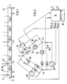
- the heating block of a continuous-flow heater is shown schematically in FIG. Water flows in the direction of arrow 10 into the heating block and leaves it in the direction of arrow 12.
- the tube 14 defines the flow path of the water.
- six resistors R1, R2, R3, R4, R5 and R6 are arranged one after the other in the flow path, so that the water passes the resistors R1, R2, ..., R6 serving as heating elements one after the other and necessarily in good order , even thermal contact comes with each individual heating element.
- the resistors R1, R2, ..., R6 are provided with electrical supply and discharge lines 16, 18 (only shown for R1).
- a temperature sensor F1 is arranged, which measures the inlet temperature T1.
- a further temperature sensor F2 which measures the temperature of the water after passing through the resistor R1, is arranged behind the resistor R1 arranged at the front in the flow direction 10. The subsequent resistors R2, R3, R4, R5 and R6 are then supplied with current in the manner to be described in such a way that the heated water at the outlet 22 of the heating block has the desired target temperature TS.
- P1 is the energy supplied to the water by means of the first resistor R1.
- the further resistors R2,..., R6 following in the flow direction of the water behind the resistor R1 must therefore supply the water with the energy PS-P1 if PS> P1. Since all the sizes of the right side are known in the above equation, the required amount of energy PS-P1, which must be supplied to the water by means of the heating elements R2, ..., R6, can be determined precisely without the measurement of the actual outlet temperature and their evaluation in a control loop would be necessary. Since the power PR of the individual ohmic resistors according to the formula results, the energy output of each individual resistor can be determined precisely, since the ohmic resistance and the applied voltage are known. If the resistance values are not exactly matched from the outset, they are measured precisely and the resistance values are stored in a memory 28 (FIG. 2). The resistance values are read into the electronic control device 26 from the memory 28.
- FIG. 2 shows the circuit of the individual resistors R1, ..., R6 according to FIG. 1 and the control circuit 26.
- Two of the resistors are connected in parallel in a delta connection to the three-phase network L1, L2 and L3.
- the voltages currently present between the three conductors L1, L2 and L3 of the three-phase network are measured by means of the voltage measuring devices 30, 30 'and 30''and entered into the control circuit 26.
- the resistors R1, ..., R6 are connected by thyristors or triacs 32, 34 or switches 36, 36 ', 36 "and 36' ⁇ , which are controlled by the electronic control device 26.
- the voltages present at the individual resistors R1, ..., R6 correspond to the voltages between the conductors L1, L2 and L3 of the three-phase network and are entered into the electronic control device 26 after the measurement of their instantaneous values and when calculating the values for the individual resistors required heating power used.
- the resistors R2,..., R6 following the resistor R1 are supplied with current in such a way that they emit the total energy calculated above (PS-P1).
- a single resistor from the R2 series of resistors, ... or several resistors can be selected.
- some of the resistors can also be supplied with current in a pulsed manner, according to FIG. 2, for example in addition to resistor R1, resistor R2, which is controlled by a thyristor or a triac will.
- the resistor R1 With low flow rates and a low target temperature TS, it can happen that the resistor R1 already generates a heating power with which the desired target temperature is exceeded, i.e. T2> TS.
- the power of the first resistor R1 is e.g. regulated to a lower value by clocking by means of the control circuit 26.
- the measurement of the temperature T2 does not necessarily have to be carried out by installing a separate temperature sensor F2, rather a material with a suitable resistance temperature coefficient can be used for the resistor R1, so that the measured value of the resistor R1 can be used Temperature T2 results.
- the resistance measurement is carried out either by measuring the applied voltage and the load current generated by it, or separately from the power circuit with the interposition of a high-pass filter by a resistance measuring device provided in the control circuit 26, which works with a correspondingly higher-frequency measuring voltage.
- the set temperature setpoints at the device outlet can be maintained during normal operation, regardless of the inlet temperature T1, the flow rate of the water and the mains voltage.
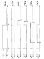
- a particularly fluctuating course of the outlet temperature of the water with very sudden changes in the flow rate, or also the water inlet temperature T1 is achieved when the control of the power output by the individual resistors R1, ..., R6 is timed to the geometrical arrangement of the resistors is matched in tube 14. It is therefore taken into account that the resistors R2, ..., R6 have different distances from the measuring resistor R1, which will be explained in more detail below with reference to FIG. 3.
- FIG. 3a the flow rate Q of the water is plotted over time, while Figures 3b to 3f each show the outputs P1, ..., or P5 given by the individual resistors R1, ..., R5 with the same time scale.
- the delay time t2-t1 results from the volume of the tube 14 between the resistors R1 and R4 on the one hand and the amount of water flowing through Q1 on the other hand. Since the volume of the tube 14 is known and the flow rate can be determined from the required temperature rise TS-T1 and the calculated required heating power PS, there is also the required delay time t2-t1, which is calculated in the control circuit 26. The same procedure is followed when the other resistors are switched on.
- the controller is therefore designed so that at time t3 only the resistor R5 is switched off, while in addition to the resistor R4, the resistors R3 and R2 are switched on.
- the resistor R4 is switched off at the time t4 and after a further delay at the time t5 the resistor R3 and finally at the time t6 the resistor R2 is switched off, so that the water at the outlet 22 exits at the desired set temperature TS.
- the delay times t4-t3, t5-t3 and t6-t3 are analogous to that described above from the volume of the heating block (tube 14) between the Resistances and the flow rates determined.
- the programs required for the corresponding control of the switches 32, 34 and 36 for the power supply of the resistors R1, ..., R6 can be loaded into known microprocessors.
Landscapes
- Physics & Mathematics (AREA)
- General Physics & Mathematics (AREA)
- Engineering & Computer Science (AREA)
- Automation & Control Theory (AREA)
- Control Of Resistance Heating (AREA)
- Instantaneous Water Boilers, Portable Hot-Water Supply Apparatuses, And Control Of Portable Hot-Water Supply Apparatuses (AREA)
- Control Of Temperature (AREA)
- Resistance Heating (AREA)
- Air-Conditioning For Vehicles (AREA)
- Heat-Pump Type And Storage Water Heaters (AREA)
Claims (8)
- Chauffe-eau instantané, comprenant- un trajet de courant (10, 20) pour l'eau à chauffer, dans lequel un nombre d'éléments chauffants (R1 ... R6), tels que des résistances de chauffage, par exemple, est disposé de manière que l'eau à chauffer les passe l'un après l'autre,- un dispositif de mesure de température (F1), au moins, au droit de l'entrée (20) de l'eau dans le chauffe-eau instantané, et- un circuit de contrôle (26) destiné à contrôler la capacité de chauffage d'éléments chauffants sélectionnés (R2 ... R6), de manière à obtenir à la sortie (22) du chauffe-eau instantané de l'eau chauffée à une certaine température demandée (TS),caractérisé en ce que
des moyens (F2; R1) sont prévus, destinés à mesurer l'augmentation de la température (T2-T1) de l'eau, effectuée par un élément chauffant (R1) ou par une partie des éléments chauffants (R1, ..., R6), et en ce que la capacité de chauffage d'autres éléments chauffants (R2 ... R6), sélectionnés et disposés en amont ou en aval, est contrôlée en fonction de l'augmentation de température mesurée (T2-T1) et de la température demandée (TS). - Chauffe-eau instantané selon la revendication 1,
caractérisé en ce que
l'on mesure l'augmentation de température (T2-T1) de l'eau effectuée par l'élément chauffant (R1) le plus proche de l'entrée (10), et que l'on contrôle la capacité de chauffage d'éléments chauffants sélectionnés (R2, ..., R6), disposés en aval. - Chauffe-eau instantané selon l'une quelconque des revendications 1 ou 2,
caractérisé en ce que
une sonde de température (F1 ou F2) est disposée dans le trajet de courant (10, 20) de l'eau avant et après respectivement un élément chauffant (R1) ou quelques éléments chauffants parmi le nombre d'éléments chauffants. - Chauffe-eau instantané selon l'une quelconque des revendications précédentes,
caractérisé en ce que
la capacité de chauffage (PS-P1) des éléments chauffants (R2, ..., R6) disposés en aval ou en amont, est capable d'être contrôlée en fonction du volume du trajet de courant situé entre l'élément chauffant avant (R1) et les éléments chauffants suivants sélectionnés (R2 ... R6). - Chauffe-eau instantané selon l'une quelconque des revendications précédentes,
caractérisé en ce que
l'on a prévu, comme des éléments chauffants, des résistances (R1 ... R6) dont les valeurs de résistance sont mesurées et stockées dans un dispositif de mémoire (28), susceptible d'être relié au circuit de contrôle (26). - Chauffe-eau instantané selon l'une quelconque des revendications précédentes,
caractérisé en ce que
les tensions instantanées appliquées aux éléments chauffants (R1 ... R6) sont mesurées et introduites dans le circuit de contrôle (26) et sont prises en compte dans le contrôle de la capacité de chauffage. - Chauffe-eau instantané selon l'une quelconque des revendications précédentes,
caractérisé en ce que
les éléments chauffants (R1 ... R6) sont connectés par groupes, montés en delta, à un réseau de courant alternatif triphasé (L1, L2, L3). - Chauffe-eau instantané selon l'une quelconque des revendications précédentes,
caractérisé en ce que
durant le contrôle de la capacité de chauffage, l'un des éléments chauffants suivants (R2 ... R6), au moins, est alimenté en courant à impulsions.
Priority Applications (1)
| Application Number | Priority Date | Filing Date | Title |
|---|---|---|---|
| AT86117216T ATE60954T1 (de) | 1985-12-27 | 1986-12-10 | Durchlauferhitzer. |
Applications Claiming Priority (2)
| Application Number | Priority Date | Filing Date | Title |
|---|---|---|---|
| DE3546214 | 1985-12-27 | ||
| DE19853546214 DE3546214A1 (de) | 1985-12-27 | 1985-12-27 | Durchlauferhitzer |
Publications (3)
| Publication Number | Publication Date |
|---|---|
| EP0229323A2 EP0229323A2 (fr) | 1987-07-22 |
| EP0229323A3 EP0229323A3 (en) | 1988-12-07 |
| EP0229323B1 true EP0229323B1 (fr) | 1991-02-20 |
Family
ID=6289621
Family Applications (1)
| Application Number | Title | Priority Date | Filing Date |
|---|---|---|---|
| EP86117216A Expired - Lifetime EP0229323B1 (fr) | 1985-12-27 | 1986-12-10 | Chauffe-eau instantané |
Country Status (4)
| Country | Link |
|---|---|
| EP (1) | EP0229323B1 (fr) |
| JP (1) | JPH0782900B2 (fr) |
| AT (1) | ATE60954T1 (fr) |
| DE (2) | DE3546214A1 (fr) |
Families Citing this family (7)
| Publication number | Priority date | Publication date | Assignee | Title |
|---|---|---|---|---|
| DE3616848C2 (de) * | 1984-11-16 | 1995-02-02 | Vaillant Joh Gmbh & Co | Schaltungsanordnung zur Durchführung des Verfahrens nach einem der Ansprüche 1 bis 12 des Hauptpatents (PCT-Anmeldung PCT DE 85/00474) |
| AT403106B (de) * | 1986-04-24 | 1997-11-25 | Vaillant Gmbh | Betriebsverfahren für einen elektrischen durchlauferhitzer |
| CH677854A5 (fr) * | 1989-01-05 | 1991-06-28 | Vaillant Gmbh | |
| DE4020502A1 (de) * | 1989-07-01 | 1991-01-10 | Vaillant Joh Gmbh & Co | Verfahren zur extrapolation einer sich zeitlich aendernden messgroesse |
| AT407938B (de) * | 1993-12-13 | 2001-07-25 | Vaillant Gmbh | Verfahren zum steuern der energiezufuhr für die aufheizung von wasser bei einem elektrisch beheizten durchlauferhitzer |
| DE4344244C2 (de) * | 1993-12-23 | 2003-03-06 | Bsh Bosch Siemens Hausgeraete | Elektrischer Durchlauferhitzer |
| DE19545719A1 (de) * | 1995-12-07 | 1997-06-12 | Helmut Prof Dr Ing Roeck | Verfahren zur Temperaturregelung von Duchlauferhitzern |
Family Cites Families (4)
| Publication number | Priority date | Publication date | Assignee | Title |
|---|---|---|---|---|
| DE2602868C2 (de) * | 1976-01-27 | 1978-08-17 | Joh. Vaillant Kg, 5630 Remscheid | Einrichtung zum Regeln der Auslauftemperatur eines elektrisch beheizten Durchlauferhitzers |
| GB2102164B (en) * | 1981-06-25 | 1985-09-04 | Woolhouse Limited Norman | Temperature sensing means |
| DE3304322A1 (de) * | 1983-02-09 | 1984-08-09 | Stiebel Eltron Gmbh & Co Kg, 3450 Holzminden | Elektrischer durchlauferhitzer |
| DE3415542A1 (de) * | 1984-04-26 | 1985-10-31 | Stiebel Eltron Gmbh & Co Kg, 3450 Holzminden | Steuerung eines elektrischen durchlauferhitzers |
-
1985
- 1985-12-27 DE DE19853546214 patent/DE3546214A1/de not_active Withdrawn
-
1986
- 1986-12-10 DE DE8686117216T patent/DE3677580D1/de not_active Expired - Fee Related
- 1986-12-10 EP EP86117216A patent/EP0229323B1/fr not_active Expired - Lifetime
- 1986-12-10 AT AT86117216T patent/ATE60954T1/de not_active IP Right Cessation
- 1986-12-17 JP JP61302770A patent/JPH0782900B2/ja not_active Expired - Lifetime
Also Published As
| Publication number | Publication date |
|---|---|
| DE3546214A1 (de) | 1987-07-02 |
| ATE60954T1 (de) | 1991-03-15 |
| DE3677580D1 (de) | 1991-03-28 |
| JPS62168359A (ja) | 1987-07-24 |
| EP0229323A2 (fr) | 1987-07-22 |
| JPH0782900B2 (ja) | 1995-09-06 |
| EP0229323A3 (en) | 1988-12-07 |
Similar Documents
| Publication | Publication Date | Title |
|---|---|---|
| DE3415542C2 (fr) | ||
| EP0229323B1 (fr) | Chauffe-eau instantané | |
| EP0189446B1 (fr) | Dispositif électronique de réglage de puissance pour un chauffe-eau électrique rapide avec réglage de la température de sortie | |
| EP1686329B1 (fr) | Appareil pour chauffer de l'eau | |
| DE4006186C2 (de) | Verfahren zur Regelung der Drehzahl einer von einem drehzahlgeregelten Elektromotor angetriebenen Pumpe | |
| DE3529257A1 (de) | Verfahren und anordnung zur ermittlung der waermeabgabe von heizflaechen einer heizungsanlage | |
| DE4344244C2 (de) | Elektrischer Durchlauferhitzer | |
| DE2602868B1 (de) | Einrichtung zum regeln der auslauftemperatur eines elektrisch beheizten durchlauferhitzers | |
| AT392854B (de) | Verfahren zum steuern der leistung eines elektrisch beheizten durchlauferhitzers | |
| DE2342264C3 (de) | Temperaturregler für ein drehstrombeheiztes Gerät | |
| DE2943081A1 (de) | Sammelheizung mit einem umlaufenden heizmedium | |
| DE3900284C2 (fr) | ||
| DE2539117C3 (de) | Verfahren und Einrichtung zur Aufladung einer elektrischen Speicherheizung | |
| DE10027656A1 (de) | Heizungsanlage mit mindestens zwei Heizkreisen | |
| DE3426046A1 (de) | Elektrischer durchlauferhitzer mit regelbarer auslauftemperatur | |
| DE2452569C3 (de) | Regeleinrichtung für einen elektrisch beheizten Durchlauferhitzer | |
| DE3712648C2 (fr) | ||
| CH627272A5 (en) | Device for determining the optical transparency of a flowing medium | |
| DE2916169B1 (de) | Vorrichtung zur Regelung der Vorlauftemperatur in einer Sammelheizungsanlage | |
| AT396851B (de) | Verfahren zur steuerung eines durchlaufwasserheizers | |
| AT395483B (de) | Rein elektrisch beheizter durchlauferhitzer mit vorrichtung zum ermitteln des wasserdurchsatzes | |
| DE860088C (de) | Stromregler, insbesondere fuer messtechnische Zwecke | |
| DE19531134A1 (de) | Verfahren und Einrichtung zur Einstellung einer vorgebbaren Auslauftemperatur eines elektrischen Durchlauferhitzers | |
| DE2858254C2 (de) | Vorrichtung zur Regelung der Auslauftemperatur bei elektrischen Durchlauferhitzern | |
| DE722863C (de) | Selbsttaetige Regeleinrichtung |
Legal Events
| Date | Code | Title | Description |
|---|---|---|---|
| PUAI | Public reference made under article 153(3) epc to a published international application that has entered the european phase |
Free format text: ORIGINAL CODE: 0009012 |
|
| AK | Designated contracting states |
Kind code of ref document: A2 Designated state(s): AT BE CH DE FR GB IT LI |
|
| PUAL | Search report despatched |
Free format text: ORIGINAL CODE: 0009013 |
|
| AK | Designated contracting states |
Kind code of ref document: A3 Designated state(s): AT BE CH DE FR GB IT LI |
|
| 17P | Request for examination filed |
Effective date: 19890509 |
|
| 17Q | First examination report despatched |
Effective date: 19900618 |
|
| GRAA | (expected) grant |
Free format text: ORIGINAL CODE: 0009210 |
|
| AK | Designated contracting states |
Kind code of ref document: B1 Designated state(s): AT BE CH DE FR GB IT LI |
|
| REF | Corresponds to: |
Ref document number: 60954 Country of ref document: AT Date of ref document: 19910315 Kind code of ref document: T |
|
| REF | Corresponds to: |
Ref document number: 3677580 Country of ref document: DE Date of ref document: 19910328 |
|
| ITF | It: translation for a ep patent filed |
Owner name: BARZANO' E ZANARDO MILANO S.P.A. |
|
| GBT | Gb: translation of ep patent filed (gb section 77(6)(a)/1977) | ||
| ET | Fr: translation filed | ||
| PLBI | Opposition filed |
Free format text: ORIGINAL CODE: 0009260 |
|
| 26 | Opposition filed |
Opponent name: JOH. VAILLANT GMBH U. CO Effective date: 19911030 |
|
| PGFP | Annual fee paid to national office [announced via postgrant information from national office to epo] |
Ref country code: CH Payment date: 19951211 Year of fee payment: 10 |
|
| PGFP | Annual fee paid to national office [announced via postgrant information from national office to epo] |
Ref country code: BE Payment date: 19960109 Year of fee payment: 10 |
|
| APAC | Appeal dossier modified |
Free format text: ORIGINAL CODE: EPIDOS NOAPO |
|
| PLBN | Opposition rejected |
Free format text: ORIGINAL CODE: 0009273 |
|
| STAA | Information on the status of an ep patent application or granted ep patent |
Free format text: STATUS: OPPOSITION REJECTED |
|
| 27O | Opposition rejected |
Effective date: 19950704 |
|
| PG25 | Lapsed in a contracting state [announced via postgrant information from national office to epo] |
Ref country code: LI Effective date: 19961231 Ref country code: CH Effective date: 19961231 Ref country code: BE Effective date: 19961231 |
|
| BERE | Be: lapsed |
Owner name: ELEKTROMANUFAKTUR ZANGENSTEIN HANAUER G.M.B.H. & Effective date: 19961231 |
|
| REG | Reference to a national code |
Ref country code: CH Ref legal event code: PL |
|
| PGFP | Annual fee paid to national office [announced via postgrant information from national office to epo] |
Ref country code: GB Payment date: 19971218 Year of fee payment: 12 |
|
| PGFP | Annual fee paid to national office [announced via postgrant information from national office to epo] |
Ref country code: FR Payment date: 19971222 Year of fee payment: 12 Ref country code: AT Payment date: 19971222 Year of fee payment: 12 |
|
| PGFP | Annual fee paid to national office [announced via postgrant information from national office to epo] |
Ref country code: DE Payment date: 19971230 Year of fee payment: 12 |
|
| PG25 | Lapsed in a contracting state [announced via postgrant information from national office to epo] |
Ref country code: GB Free format text: LAPSE BECAUSE OF NON-PAYMENT OF DUE FEES Effective date: 19981210 Ref country code: AT Free format text: LAPSE BECAUSE OF NON-PAYMENT OF DUE FEES Effective date: 19981210 |
|
| GBPC | Gb: european patent ceased through non-payment of renewal fee |
Effective date: 19981210 |
|
| PG25 | Lapsed in a contracting state [announced via postgrant information from national office to epo] |
Ref country code: FR Free format text: LAPSE BECAUSE OF NON-PAYMENT OF DUE FEES Effective date: 19990831 |
|
| REG | Reference to a national code |
Ref country code: FR Ref legal event code: ST |
|
| PG25 | Lapsed in a contracting state [announced via postgrant information from national office to epo] |
Ref country code: DE Free format text: LAPSE BECAUSE OF NON-PAYMENT OF DUE FEES Effective date: 19991001 |
|
| APAH | Appeal reference modified |
Free format text: ORIGINAL CODE: EPIDOSCREFNO |
|
| PG25 | Lapsed in a contracting state [announced via postgrant information from national office to epo] |
Ref country code: IT Free format text: LAPSE BECAUSE OF NON-PAYMENT OF DUE FEES Effective date: 20051210 |