EP0229323B1 - Continuous flow heater - Google Patents
Continuous flow heater Download PDFInfo
- Publication number
- EP0229323B1 EP0229323B1 EP86117216A EP86117216A EP0229323B1 EP 0229323 B1 EP0229323 B1 EP 0229323B1 EP 86117216 A EP86117216 A EP 86117216A EP 86117216 A EP86117216 A EP 86117216A EP 0229323 B1 EP0229323 B1 EP 0229323B1
- Authority
- EP
- European Patent Office
- Prior art keywords
- water
- heating
- heating elements
- temperature
- continuous flow
- Prior art date
- Legal status (The legal status is an assumption and is not a legal conclusion. Google has not performed a legal analysis and makes no representation as to the accuracy of the status listed.)
- Expired - Lifetime
Links
Images
Classifications
-
- G—PHYSICS
- G05—CONTROLLING; REGULATING
- G05D—SYSTEMS FOR CONTROLLING OR REGULATING NON-ELECTRIC VARIABLES
- G05D23/00—Control of temperature
- G05D23/19—Control of temperature characterised by the use of electric means
- G05D23/20—Control of temperature characterised by the use of electric means with sensing elements having variation of electric or magnetic properties with change of temperature
- G05D23/24—Control of temperature characterised by the use of electric means with sensing elements having variation of electric or magnetic properties with change of temperature the sensing element having a resistance varying with temperature, e.g. a thermistor
-
- G—PHYSICS
- G05—CONTROLLING; REGULATING
- G05D—SYSTEMS FOR CONTROLLING OR REGULATING NON-ELECTRIC VARIABLES
- G05D23/00—Control of temperature
- G05D23/19—Control of temperature characterised by the use of electric means
- G05D23/1906—Control of temperature characterised by the use of electric means using an analogue comparing device
- G05D23/1912—Control of temperature characterised by the use of electric means using an analogue comparing device whose output amplitude can take more than two discrete values
Definitions
- the invention relates to a water heater with a flow path for the water to be heated, in which a plurality of heating elements, such as heating resistors, are arranged such that they pass through the water to be heated in order, at least one temperature measuring device at the inlet of the water in the instantaneous water heater and with a control circuit for controlling the heating power of selected heating elements in order to obtain water at the outlet from the instantaneous water heater with a predetermined target temperature.
- a plurality of heating elements such as heating resistors
- DE-OS 34 15 542 describes a generic instantaneous water heater in which the outlet temperature of the water is regulated to a predetermined setpoint without using a flow meter.
- the temperature is measured at the entrance and at the exit of the instantaneous water heater by means of sensors and the heating power of several heating elements arranged one behind the other in the flow path is regulated accordingly.
- the heating output is initially increased approximately to a target heating output determined by the inlet temperature and the outlet temperature, which is required to reach the target temperature at the given flow rate and inlet temperature, whereupon the outlet temperature is adjusted to the target temperature in a subsequent control phase.
- the invention has for its object to develop a generic instantaneous water heater in such a way that even when changes in the operating parameters, such as the flow rate and the instantaneous mains voltage, an exact maintenance of the target temperature at the outlet is ensured.
- this object is achieved in that devices are provided to measure the temperature increase of the water by a heating element or a part of the heating elements and that the heating power of selected other upstream or downstream heating elements is controlled in accordance with the measured temperature increase and the target temperature.
- the heating element which is closest to the inlet of the instantaneous water heater is preferably selected for the temperature measurement. Instead of measuring the temperature at the inlet and at the outlet of the instantaneous water heater, a much shorter control path is selected according to the invention, which extends from the inlet to behind the first heating element. If the inlet temperature at the inlet of the instantaneous water heater is known and the heating power of the heating element at the front is known, the temperature increase in the water after passing this heating element results in all the information required to control the outlet temperature to the specified setpoint with the subsequent heating elements. For example, the flow rate of the water with a known inlet temperature and known heating power of the heating element arranged at the front is a clear function of the temperature increase measured after passing through this heating element.
- temperature sensors are provided in front of and behind the heating element arranged at the front, which measure the temperature increase required for the control.
- the temperature increase can also be measured directly by means of the heating element selected for temperature measurement in that the latter is designed as a heating resistor with a suitable resistance temperature coefficient, so that the temperature can be determined by measuring the resistance value of the heating element.
- a particularly precise adaptation of the outlet temperature to the desired value is achieved in a preferred embodiment of the invention in that the heating power of the subsequent heating elements is controlled as a function of the volume of the flow path between the heating element selected for temperature measurement and the other heating elements selected for heating.
- Standard resistors can be provided as heating elements, but these are relatively expensive. In a preferred embodiment of the invention, therefore, not matched heating resistors are used and the actual resistance value is measured. The measurement results are stored and entered into the electronic control device for regulating the heating power and taken into account accordingly.
- This measure has the particular advantage that when the heating block is replaced with the heating elements on site by the installer, no adjustment work has to be carried out, since the resistance values of the newly installed heating block are entered directly into the electronic control device after installation, where the new values are given the determination of the heating outputs are taken into account.
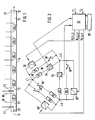
- the heating block of a continuous-flow heater is shown schematically in FIG. Water flows in the direction of arrow 10 into the heating block and leaves it in the direction of arrow 12.
- the tube 14 defines the flow path of the water.
- six resistors R1, R2, R3, R4, R5 and R6 are arranged one after the other in the flow path, so that the water passes the resistors R1, R2, ..., R6 serving as heating elements one after the other and necessarily in good order , even thermal contact comes with each individual heating element.
- the resistors R1, R2, ..., R6 are provided with electrical supply and discharge lines 16, 18 (only shown for R1).
- a temperature sensor F1 is arranged, which measures the inlet temperature T1.
- a further temperature sensor F2 which measures the temperature of the water after passing through the resistor R1, is arranged behind the resistor R1 arranged at the front in the flow direction 10. The subsequent resistors R2, R3, R4, R5 and R6 are then supplied with current in the manner to be described in such a way that the heated water at the outlet 22 of the heating block has the desired target temperature TS.
- P1 is the energy supplied to the water by means of the first resistor R1.
- the further resistors R2,..., R6 following in the flow direction of the water behind the resistor R1 must therefore supply the water with the energy PS-P1 if PS> P1. Since all the sizes of the right side are known in the above equation, the required amount of energy PS-P1, which must be supplied to the water by means of the heating elements R2, ..., R6, can be determined precisely without the measurement of the actual outlet temperature and their evaluation in a control loop would be necessary. Since the power PR of the individual ohmic resistors according to the formula results, the energy output of each individual resistor can be determined precisely, since the ohmic resistance and the applied voltage are known. If the resistance values are not exactly matched from the outset, they are measured precisely and the resistance values are stored in a memory 28 (FIG. 2). The resistance values are read into the electronic control device 26 from the memory 28.
- FIG. 2 shows the circuit of the individual resistors R1, ..., R6 according to FIG. 1 and the control circuit 26.
- Two of the resistors are connected in parallel in a delta connection to the three-phase network L1, L2 and L3.
- the voltages currently present between the three conductors L1, L2 and L3 of the three-phase network are measured by means of the voltage measuring devices 30, 30 'and 30''and entered into the control circuit 26.
- the resistors R1, ..., R6 are connected by thyristors or triacs 32, 34 or switches 36, 36 ', 36 "and 36' ⁇ , which are controlled by the electronic control device 26.
- the voltages present at the individual resistors R1, ..., R6 correspond to the voltages between the conductors L1, L2 and L3 of the three-phase network and are entered into the electronic control device 26 after the measurement of their instantaneous values and when calculating the values for the individual resistors required heating power used.
- the resistors R2,..., R6 following the resistor R1 are supplied with current in such a way that they emit the total energy calculated above (PS-P1).
- a single resistor from the R2 series of resistors, ... or several resistors can be selected.
- some of the resistors can also be supplied with current in a pulsed manner, according to FIG. 2, for example in addition to resistor R1, resistor R2, which is controlled by a thyristor or a triac will.
- the resistor R1 With low flow rates and a low target temperature TS, it can happen that the resistor R1 already generates a heating power with which the desired target temperature is exceeded, i.e. T2> TS.
- the power of the first resistor R1 is e.g. regulated to a lower value by clocking by means of the control circuit 26.
- the measurement of the temperature T2 does not necessarily have to be carried out by installing a separate temperature sensor F2, rather a material with a suitable resistance temperature coefficient can be used for the resistor R1, so that the measured value of the resistor R1 can be used Temperature T2 results.
- the resistance measurement is carried out either by measuring the applied voltage and the load current generated by it, or separately from the power circuit with the interposition of a high-pass filter by a resistance measuring device provided in the control circuit 26, which works with a correspondingly higher-frequency measuring voltage.
- the set temperature setpoints at the device outlet can be maintained during normal operation, regardless of the inlet temperature T1, the flow rate of the water and the mains voltage.
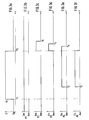
- a particularly fluctuating course of the outlet temperature of the water with very sudden changes in the flow rate, or also the water inlet temperature T1 is achieved when the control of the power output by the individual resistors R1, ..., R6 is timed to the geometrical arrangement of the resistors is matched in tube 14. It is therefore taken into account that the resistors R2, ..., R6 have different distances from the measuring resistor R1, which will be explained in more detail below with reference to FIG. 3.
- FIG. 3a the flow rate Q of the water is plotted over time, while Figures 3b to 3f each show the outputs P1, ..., or P5 given by the individual resistors R1, ..., R5 with the same time scale.
- the delay time t2-t1 results from the volume of the tube 14 between the resistors R1 and R4 on the one hand and the amount of water flowing through Q1 on the other hand. Since the volume of the tube 14 is known and the flow rate can be determined from the required temperature rise TS-T1 and the calculated required heating power PS, there is also the required delay time t2-t1, which is calculated in the control circuit 26. The same procedure is followed when the other resistors are switched on.
- the controller is therefore designed so that at time t3 only the resistor R5 is switched off, while in addition to the resistor R4, the resistors R3 and R2 are switched on.
- the resistor R4 is switched off at the time t4 and after a further delay at the time t5 the resistor R3 and finally at the time t6 the resistor R2 is switched off, so that the water at the outlet 22 exits at the desired set temperature TS.
- the delay times t4-t3, t5-t3 and t6-t3 are analogous to that described above from the volume of the heating block (tube 14) between the Resistances and the flow rates determined.
- the programs required for the corresponding control of the switches 32, 34 and 36 for the power supply of the resistors R1, ..., R6 can be loaded into known microprocessors.
Abstract
Description
Die Erfindung betrifft einen Durchlauferhitzer für Wasser mit einem Strömungsweg für das zu erhitzende Wasser, in dem eine Mehrzahl von Heizelementen, wie beispielsweise Heizwiderstände, derart angeordnet sind, daß sie das zu erhitzende Wasser der Reihe nach passiert, zumindest einer Temperaturmeßeinrichtung am Einlauf des Wassers in den Durchlauferhitzer und mit einer Steuerschaltung zum Steuern der Heizleistung ausgewählter Heizelemente, um am Auslauf aus dem Durchlauferhitzer erhitztes Wasser mit einer vorgegebenen Solltemperatur zu erhalten.The invention relates to a water heater with a flow path for the water to be heated, in which a plurality of heating elements, such as heating resistors, are arranged such that they pass through the water to be heated in order, at least one temperature measuring device at the inlet of the water in the instantaneous water heater and with a control circuit for controlling the heating power of selected heating elements in order to obtain water at the outlet from the instantaneous water heater with a predetermined target temperature.
Elektrisch beheizte Durchlauferhitzer, die das Wasser unmittelbar vor dem Verbrauch erhitzen, sind in unterschiedlichsten Ausführungen bekannt. Häufig wird bei Überschreiten einer Mindest-Durchlaufmenge des fließenden Wassers über einen membranbetätigten Schalter eine erste, relativ niederige Heizleistung eingeschaltet und über weitere Kontakte des Membranschalters bei Überschreiten eines höheren Grenzwertes der Durchflußmenge die Heizleistung auf eine höhere Stufe umgeschaltet. Bei derartigen Durchlauferhitzern wird die Auslauftemperatur des Wassers nicht auf einen vorgegebenen Sollwert geregelt. Vielmehr ist die Wassertemperatur von der Durchflußmenge, der Eintrittstemperatur des Wassers sowie dem momentanen Wert der Netzspannung abhängig.Electrically heated instantaneous water heaters, which heat the water immediately before consumption, are known in a wide variety of designs. Frequently, when a minimum flow rate of the flowing water is exceeded, a first, relatively low heating power is switched on via a membrane-operated switch and the heating power is switched to a higher level via further contacts of the membrane switch when a higher limit value of the flow rate is exceeded. In the case of such instantaneous heaters, the outlet temperature of the water is not regulated to a predetermined setpoint. Rather, the water temperature depends on the flow rate, the inlet temperature of the water and the current value of the mains voltage.
Es ist auch bekannt, Durchflußmeßgeräte für das strömende Wasser einzusetzen, beispielsweise in Form eines Flügelrades, und auch die Wassertemperatur am Auslauf des Durchlauferhitzers zu messen. Mittels der gemessenen Durchflußmenge und des ebenfalls gemessenen Auslauftemperatur kann die Heizleistung geregelt werden.It is also known to use flow measuring devices for the flowing water, for example in the form of an impeller, and also to measure the water temperature at the outlet of the instantaneous water heater. The heating output can be regulated by means of the measured flow rate and the outlet temperature also measured.
Durchflußmeßgeräte mit der erforderlichen Genauigkeit sind teuer und auch störanfällig. In der DE-OS 34 15 542 wird ein gattungsgemäßer Durchlauferhitzer beschrieben, bei dem die Auslauftemperatur des Wassers ohne Verwendung eines Durchflußmeßgerätes auf einen vorgegebenen Sollwert geregelt wird. Hierzu wird dort am Eingang und am Ausgang des Durchlauferhitzers mittels Meßfühlern die Temperatur gemessen und die Heizleistung von mehreren im Strömungsweg hintereinander angeordneten Heizelementen wird entsprechend geregelt. In einer Steuerphase wird die Heizleistung zunächst annähernd bis an eine durch die Einlauftemperatur und die Auslauftemperatur bestimmte Sollheizleistung erhöht, welche zum Erreichen der Solltemperatur bei der gegebenen Durchflußmenge und Einlauftemperatur erforderlich ist, worauf dann in einer nachfolgenden Regelphase die Auslauftemperatur auf die Solltemperatur nachgeregelt wird. Eine derartige Regelung unter Verwendung der Einlauf- und der Auslauftemperatur hat den Nachteil, daß das Wasser erst nach dem Durchlaufen des Heizblockes den Temperaturfühler am Ausgang erreicht. Somit verstreicht eine beträchtliche "Totzeit", welche zudem von der Durchflußmenge abhängt. Insbesondere bei sich schnell ändernden Durchflußmengen ergeben sich Unzulänglichkeiten bei der Temperaturregelung. Das System ist insgesamt zu "träge", um sich schnell ändernden Bedingungen anpassen zu können. Durch die lange Regelstrecke ergeben sich bei schnellen Änderungen der Durchflußmenge deutliche Abweichungen der Wassertemperatur am Auslauf von der Solltemperatur.Flow meters with the required accuracy are expensive and also prone to failure. DE-OS 34 15 542 describes a generic instantaneous water heater in which the outlet temperature of the water is regulated to a predetermined setpoint without using a flow meter. For this purpose, the temperature is measured at the entrance and at the exit of the instantaneous water heater by means of sensors and the heating power of several heating elements arranged one behind the other in the flow path is regulated accordingly. In a control phase, the heating output is initially increased approximately to a target heating output determined by the inlet temperature and the outlet temperature, which is required to reach the target temperature at the given flow rate and inlet temperature, whereupon the outlet temperature is adjusted to the target temperature in a subsequent control phase. Such a control using the inlet and outlet temperatures has the disadvantage that the water only reaches the temperature sensor at the outlet after it has passed through the heating block. Thus a considerable "dead time" elapses, which also depends on the flow rate. In particular with rapidly changing flow rates, there are shortcomings in temperature control. Overall, the system is too "sluggish" to adapt to rapidly changing conditions. Due to the long controlled system, rapid changes in the flow rate result in significant deviations in the water temperature at the outlet from the target temperature.
Der Erfindung liegt die Aufgabe zugrunde, einen gattungsgemäßen Durchlauferhitzer derart weiterzubilden, daß auch bei Änderungen der Betriebsparameter, wie der Durchflußgeschwindigkeit und der momentanen Netzspannung, eine genaue Einhaltung der Solltemperatur am Auslauf gewährleistet ist.The invention has for its object to develop a generic instantaneous water heater in such a way that even when changes in the operating parameters, such as the flow rate and the instantaneous mains voltage, an exact maintenance of the target temperature at the outlet is ensured.
Erfindungsgemäß wird diese Aufgabe dadurch gelöst, daß Einrichtungen vorgesehen sind, um die Temperaturerhöhung des Wassers durch ein Heizelement oder einen Teil der Heizelemente zu messen und daß die Heizleistung ausgewählter anderer, stromauf oder stromab angeordneter Heizelemente gemäß der gemessenen Temperaturerhöhung und der Solltemperatur gesteuert wird.According to the invention this object is achieved in that devices are provided to measure the temperature increase of the water by a heating element or a part of the heating elements and that the heating power of selected other upstream or downstream heating elements is controlled in accordance with the measured temperature increase and the target temperature.
Bevorzugt wird für die Temperaturmessung das Heizelement gewählt, welches dem Einlauf des Durchlauferhitzers am nächsten liegt. Anstatt die Temperatur am Einlauf und am Auslauf des Durchlauferhitzers zu messen wird erfindungsgemäß also eine wesentlich kürzere Regelstrecke gewählt, die vom Einlauf bis hinter das erste Heizelement reicht. Bei bekannter Eingangstemperatur am Einlauf des Durchlauferhitzers sowie bekannter Heizleistung des vorne angeordneten Heizelementes ergeben sich aus der nach Passieren dieses Heizelementes erzielten Temperaturerhöhung des Wassers sämtliche erforderlichen Informationen, um mit den nachfolgenden Heizelementen die Steuerung der Auslauftemperatur auf den vorgegebenen Sollwert durchzuführen. Beispielsweise ist die Durchflußmenge des Wassers bei bekannter Einlauftemperatur und bekannter Heizleistung des vorne angeordneten Heizelementes eine eindeutige Funktion der nach Passieren dieses Heizelementes gemessenen Temperaturerhöhung.The heating element which is closest to the inlet of the instantaneous water heater is preferably selected for the temperature measurement. Instead of measuring the temperature at the inlet and at the outlet of the instantaneous water heater, a much shorter control path is selected according to the invention, which extends from the inlet to behind the first heating element. If the inlet temperature at the inlet of the instantaneous water heater is known and the heating power of the heating element at the front is known, the temperature increase in the water after passing this heating element results in all the information required to control the outlet temperature to the specified setpoint with the subsequent heating elements. For example, the flow rate of the water with a known inlet temperature and known heating power of the heating element arranged at the front is a clear function of the temperature increase measured after passing through this heating element.
In einer einfachen Ausgestaltung der Erfindung sind vor und nach dem vorne angeordneten Heizelement jeweils Temperaturfühler vorgesehen, welche die für die Regelung erforderliche Temperaturerhöhung messen.In a simple embodiment of the invention, temperature sensors are provided in front of and behind the heating element arranged at the front, which measure the temperature increase required for the control.
Statt der vorstehend genannten Temperaturfühler kann die Temperaturerhöhung auch direkt mittels des zur Temperaturmessung ausgewählten Heizelementes dadurch gemessen werden, daß letzteres als Heizwiderstand mit einem geeigneten Widerstands-Temperaturkoeffizienten ausgebildet ist, so daß durch Messung des Widerstandswertes des Heizelementes die Temperatur zu bestimmen ist.Instead of the above-mentioned temperature sensors, the temperature increase can also be measured directly by means of the heating element selected for temperature measurement in that the latter is designed as a heating resistor with a suitable resistance temperature coefficient, so that the temperature can be determined by measuring the resistance value of the heating element.
Eine besonders genaue Anpassung der Auslauftemperatur an den Sollwert wird in einer bevorzugten Ausgestaltung der Erfindung dadurch erreicht, daß die Heizleistung der nachfolgenden Heizelemente in Abhängigkeit vom Volumen des Strömungsweges zwischen dem zur Temperaturmessung ausgewählten Heizelement und den für die Aufheizung ausgewählten anderen Heizelementen gesteuert wird.A particularly precise adaptation of the outlet temperature to the desired value is achieved in a preferred embodiment of the invention in that the heating power of the subsequent heating elements is controlled as a function of the volume of the flow path between the heating element selected for temperature measurement and the other heating elements selected for heating.
Es können als Heizelemente genormte Widerstände vorgesehen werden, welche allerdings relativ teuer sind. In einer bevorzugten Ausgestaltung der Erfindung werden deshalb nicht notwendig abgeglichene Heizwiderstände eingesetzt und es wird der tatsächliche Widerstandswert gemessen. Die Meßergebnisse werden gespeichert und in die elektronische Steuereinrichtung für die Regelung der Heizleistung eingegeben und entsprechend berücksichtigt. Diese Maßnahme hat insbesondere den Vorteil, daß bei einem Austausch des Heizblockes mit den Heizelementen vor Ort durch den Monteur keine Abgleicharbeiten durchgeführt werden müssen, da die Widerstandswerte des neu eingebauten Heizblockes nach dem Einbau direkt in die elektronische Steuereinrichtung eingegeben werden, wo die neuen Werte bei der Bestimmung der Heizleistungen berücksichtigt werden.Standard resistors can be provided as heating elements, but these are relatively expensive. In a preferred embodiment of the invention, therefore, not matched heating resistors are used and the actual resistance value is measured. The measurement results are stored and entered into the electronic control device for regulating the heating power and taken into account accordingly. This measure has the particular advantage that when the heating block is replaced with the heating elements on site by the installer, no adjustment work has to be carried out, since the resistance values of the newly installed heating block are entered directly into the electronic control device after installation, where the new values are given the determination of the heating outputs are taken into account.
Nachfolgend wird ein Ausführungsbeispiel der Erfindung anhand der Zeichnung näher beschrieben. Es zeigt:
- Fig. 1
- den Heizblock eines Durchlauferhitzers in schematischer Darstellung;
- Fig. 2
- einen Schaltplan für den in Fig. 1 dargestellten Durchlauferhitzer und
- Fig. 3
- ein Beispiel für die zeitliche Steuerung der Heizleistung einzelner Heizelemente.
- Fig. 1
- the heating block of a water heater in a schematic representation;
- Fig. 2
- a circuit diagram for the water heater shown in Fig. 1 and
- Fig. 3
- an example of the timing of the heating output of individual heating elements.
In Fig. l ist der Heizblock eines Durchlauferhitzers schematisch dargestellt. Wasser strömt in Richtung des Pfeiles 10 in den Heizblock und verläßt ihn in Richtung des Pfeiles 12. Das Rohr 14 definiert den Strömungsweg des Wassers. Im Strömungsweg sind im dargestellten Ausführungsbeispiel sechs Widerstände R1, R2, R3, R4, R5 und R6 der Reihe nach hintereinander angeordnet, so daß das Wasser die als Heizelemente dienenden Widerstände R1, R2, ..., R6 hintereinander passiert und dabei notwendig in guten, gleichmäßigen Wärmekontakt mit jedem einzelnen Heizelement kommt. Die Widerstände R1, R2, ..., R6 sind mit elektrischen Zu- und Ableitungen 16, 18 (nur für R1 gezeigt) versehen.The heating block of a continuous-flow heater is shown schematically in FIG. Water flows in the direction of
Am Einlauf 20 des Heizblockes ist ein Temperaturfühler F1 angeordnet, welcher die Einlauftemperatur T1 mißt. Hinter dem in Strömungsrichtung 10 zuvorderst angeordneten Widerstand R1 ist ein weiterer Temperaturfühler F2 angeordnet, welcher die Temperatur des Wassers nach Passieren des Widerstandes R1 mißt. Die nachfolgenden Widerstände R2, R3, R4, R5 und R6 werden dann in der noch zu beschreibenden Weise derart mit Strom versorgt, daß am Auslaß 22 des Heizblockes das erhitzte Wasser die gewünschte Solltemperatur TS aufweist.At the
Um am Auslauf 22 die gewünschte Solltemperatur TS zu erhalten, muß der durchfließenden Wassermenge insgesamt die Leistung PS zugeführt werden, die sich wie folgt ergibt:In order to obtain the desired setpoint temperature TS at
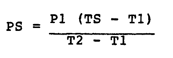

Fig. 2 zeigt die Schaltung der einzelnen Widerstände R1, ..., R6 gemäß Fig. 1 sowie die Steuerschaltung 26. Am Drehstromnetz L1, L2 und L3 sind jeweils in Dreieckschaltung zwei der Widerstände parallelgeschaltet. Die zwischen den drei Leitern L1, L2 und L3 des Drehstromnetzes momentan anliegenden Spannungen werden mittels der Spannungsmeßeinrichtungen 30, 30′ und 30′′ gemessen und in die Steuerschaltung 26 eingegeben. Die Widerstände R1, ..., R6 werden durch Thyristoren oder Triacs 32, 34 bzw. Schalter 36, 36′, 36" und 36′˝ beschaltet, welche durch die elektronische Steuereinrichtung 26 gesteuert werden.FIG. 2 shows the circuit of the individual resistors R1, ..., R6 according to FIG. 1 and the
Die an den einzelnen Widerständen R1, ..., R6 anliegenden Spannungen entsprechen den Spannungen zwischen den Leitern L1, L2 und L3 des Drehstromnetzes und werden nach der Messung ihrer momentanen Werte in die elektronische Steuereinrichtung 26 eingegeben und bei der Errechnung der für die einzelnen Widerstände erforderlichen Heizleistungen benutzt. Insgesamt werden die dem Widerstand R1 nachfolgenden Widerstände R2, ..., R6 derart mit Strom versorgt, daß sie insgesamt die oben errechnete Energie (PS-P1) abgeben. Hierzu kann je nach der erforderlichen Energie ein einzelner Widerstand aus der Widerstandsreihe R2, ... oder es können mehrere Widerstände ausgewählt werden. Um eine feinstufige Anpassung der abgegebenen Leistung an die eingestellte Solltemperatur TS zu erreichen, können einzelne der Widerstände auch getaktet (pulsierend) mit Strom versorgt werden, gemäß Fig. 2 beispielsweise neben dem Widerstand R1 der Widerstand R2, welche durch einen Thyristor oder ein Triac gesteuert werden.The voltages present at the individual resistors R1, ..., R6 correspond to the voltages between the conductors L1, L2 and L3 of the three-phase network and are entered into the
Bei geringen Durchflußmengen und einer niedrigen Solltemperatur TS kann es vorkommen, daß der Widerstand R1 bereits eine Heizleistung erzeugt, mit welcher die gewünschte Solltemperatur überschritten wird, d.h. T2 > TS. In diesem Falle wird auch die Leistung des ersten Widerstandes R1 z.B. durch Takten mittels der Steuerschaltung 26 auf einen niedrigeren Wert geregelt.With low flow rates and a low target temperature TS, it can happen that the resistor R1 already generates a heating power with which the desired target temperature is exceeded, i.e. T2> TS. In this case, the power of the first resistor R1 is e.g. regulated to a lower value by clocking by means of the
Die Messung der Temperatur T2 (Fig. 1) muß nicht unbedingt durch den Einbau eines gesonderten Temperaturfühlers F2 erfolgen, vielmehr kann für den Widerstand R1 auch ein Material mit passendem Widerstands-Temperaturkoeffizienten verwendet werden, so daß sich aus dem gemessenen Wert des Widerstandes R1 die Temperatur T2 ergibt. Die Widerstandsmessung erfolgt entweder durch Messung der anliegenden Spannung und des durch sie erzeugten Laststromes oder getrennt vom Leistungskreis unter Zwischenschaltung eines Hochpaßfilters durch eine in der Steuerschaltung 26 vorgesehene Widerstandsmeßeinrichtung, die mit einer entsprechend höherfrequenten Meßspannung arbeitet.The measurement of the temperature T2 (Fig. 1) does not necessarily have to be carried out by installing a separate temperature sensor F2, rather a material with a suitable resistance temperature coefficient can be used for the resistor R1, so that the measured value of the resistor R1 can be used Temperature T2 results. The resistance measurement is carried out either by measuring the applied voltage and the load current generated by it, or separately from the power circuit with the interposition of a high-pass filter by a resistance measuring device provided in the
Mit der vorstehend beschriebenen Steuerschaltung für einen Durchlauferhitzer können bei normalem Betrieb die eingestellten Temperatur-Sollwerte am Geräteauslauf unabhängig von der Einlauftemperatur T1, der Durchflußmenge des Wassers sowie der Netzspannung eingehalten werden.With the control circuit for a instantaneous water heater described above, the set temperature setpoints at the device outlet can be maintained during normal operation, regardless of the inlet temperature T1, the flow rate of the water and the mains voltage.
Ein besonders schwankungsfreier Verlauf der Auslauftemperatur des Wassers bei sehr sprunghaften Änderungen der Durchflußmenge, oder auch der Wasser-Einlauftemperatur T1 wird dann erreicht, wenn die Steuerung der durch die einzelnen Widerstände R1, ..., R6 abgegebenen Leistung zeitlich auf die geometrische Anordnung der Widerstände im Rohr 14 abgestimmt ist. Es wird also berücksichtigt, daß die Widerstände R2, ..., R6 unterschiedlichen Abstand zum Meß-Widerstand R1 haben, was nachfolgend anhand der Fig. 3 näher erläutert werden soll.A particularly fluctuating course of the outlet temperature of the water with very sudden changes in the flow rate, or also the water inlet temperature T1, is achieved when the control of the power output by the individual resistors R1, ..., R6 is timed to the geometrical arrangement of the resistors is matched in
In Fig. 3a ist die Durchflußmenge Q des Wassers über der Zeit aufgetragen, während die Figuren 3b bis 3f jeweils die durch die einzelnen Widerstände R1, ..., R5 abgegebenen Leistungen P1, ..., bzw. P5 mit gleichem Zeitmaßstab wiedergeben.In Fig. 3a, the flow rate Q of the water is plotted over time, while Figures 3b to 3f each show the outputs P1, ..., or P5 given by the individual resistors R1, ..., R5 with the same time scale.
Es sei angenommen, daß der Durchlauferhitzer zu Beginn der Betrachtung von einer Wassermenge Qo durchströmt wird und daß zur Aufheizung des Wassers auf die gewünschte Austrittstemperatur TS die Leistung P1 erforderlich ist, die ausschließlich durch den ersten Widerstand R1 aufgebracht wird. Das strömende Wasser hat also am in Strömungsrichtung 10 (Fig. 1) hinteren Ende des Widerstandes R1 bereits die gewünschte Temperatur erreicht. Nun wird zum Zeitpunkt t₁ die durchströmende Wassermenge plötzlich auf Q₁ erhöht. Um diese größere Wassermenge Q₁ auf die gewünschte Solltemperatur TS aufzuheizen, wird eine größere Heizleistung benötigt, die beispielsweise durch gleichzeitigen Einsatz der Heizwiderstände R4 und R5 erzeugt wird. Würde nun die Steuerschaltung 26 zum Zeitpunkt t₁ schlagartig die Leistung der Widerstände R4 und R5 einschalten, so würde das zwischen dem in Strömungsrichtung hinteren Ende des Wider standes R1 und dem vorderen Ende des Widerstandes R4 befindliche Wasser, das bereits auf die Solltemperatur TS erwärmt ist, beim Vorbeifließen an den Widerständen R4 und R5 noch weiter aufgeheizt, so daß am Auslauf 22 die Solltemperatur TS überschritten werden würde. Dies wird dadurch vermieden, daß die Widerstände R4 und R5 erst zu einem späteren Zeitpunkt t₂ zugeschaltet werden, wenn das am in Strömungsrichtung vorderen Ende des Widerstandes R1 zum Zeitpunkt t₁ anstehende Kaltwasser das vordere Ende des Widerstandes R4 erreicht hat. Die Verzögerungszeit t₂-t₁ ergibt sich aus dem Volumen des Rohres 14 zwischen den Widerständen R1 und R4 einerseits sowie aus der Menge Q₁ durchströmenden Wassers andererseits. Da der Rauminhalt des Rohres 14 bekannt ist und die durchströmende Menge aus dem erforderlichen Temperaturanstieg TS-T1 und der errechneten erforderlichen Heizleistung PS ermittelt werden kann, ergibt sich auch die erforderliche Verzögerungszeit t₂-t₁, welche in der Steuerschaltung 26 errechnet wird. Entsprechend dem vorstehend beschriebenen Beispiel wird auch bei Einschaltung der anderen Widerstände verfahren.It is assumed that a flow of water Q o is flowing through the instantaneous heater at the beginning of the observation and that the power P1, which is applied exclusively by the first resistor R1, is required to heat the water to the desired outlet temperature TS. The flowing water has therefore already reached the desired temperature at the rear end of the resistor R1 in the flow direction 10 (FIG. 1). Now at the time t₁ the amount of water flowing through is suddenly increased to Q₁. In order to heat this larger quantity of water Q 1 to the desired target temperature TS, a greater heating power is required, which is generated, for example, by the simultaneous use of the heating resistors R4 and R5. If the
Bei einer abrupten Änderung der Durchflußmenge in entgegengesetzter Richtung, d.h. von höheren Werten Q₁ auf tiefere Werte Qo ist das am vorderen Ende des Widerstandes R4 anstehende Wasser noch zu kalt. Würde also zum Zeitpunkt t₃ (Fig. 3a) die Heizleistung der Widerstände R4 und R5 schlagartig abgeschaltet, so bliebe das zwischen den Widerständen und R4 stehende Wasser unbeheizt und würde am Auslauf 22 zu kalt austreten. Die Steuerung ist deshalb so gestaltet, daß zum Zeitpunkt t₃ nur der Widerstand R5 abgeschaltet wird, während zusätzlich zum Widerstand R4 die Widerstände R3 und R2 eingeschaltet werden. Nach einer kurzen Verzögerung wird zum Zeitpunkt t₄ auch der Widerstand R4 und nach einer weiteren Verzögerung zum Zeitpunkt t₅ der Widerstand R3 und schließlich zum Zeitpunkt t₆ der Widerstand R2 abgeschaltet, so daß das Wasser am Auslauf 22 mit der gewünschten Solltemperatur TS austritt. Die Verzögerungszeiten t₄-t₃, t₅-t₃ und t₆-t₃ werden analog wie oben beschrieben aus dem Volumen des Heizblockes (Rohr 14) zwischen den Widerständen und den Durchflußmengen ermittelt. Die für die entsprechende Steuerung der Schalter 32, 34 und 36 zur Stromversorgung der Widerstände R1, ..., R6 erforderlichen Programme können in bekannte Mikroprozessoren geladen werden.With an abrupt change in the flow rate in the opposite direction, ie from higher values Q₁ to lower values Q o , the water present at the front end of the resistor R4 is still too cold. So if at time t₃ (Fig. 3a) the heating power of the resistors R4 and R5 was suddenly switched off, the water between the resistors and R4 would remain unheated and would exit at the
Es ist offensichtlich nicht entscheidend, wieviele Heizwiderstände beim vorstehend beschriebenen Durchlauferhitzer eingesetzt werden. Hinsichtlich des Aufwandes an Bauteilen und der Anzahl erforderlicher Schalter ergeben sich besonders einfache Verhältnisse, wenn insgesamt, wie gezeigt, sechs Widerstände R1, ..., R6 eingesetzt werden, deren Leistungen zueinander in Strömungsrichtung 10 des Wassers im Verhältnis 1:1:1,5:3:3:3 zueinander stehen (d.h. die Leistung des ersten Widerstandes R1 ist auf "1" normiert).It obviously does not matter how many heating resistors are used in the instantaneous water heater described above. With regard to the outlay on components and the number of switches required, there are particularly simple ratios if, as shown, a total of six resistors R1,. 5: 3: 3: 3 to each other (ie the power of the first resistor R1 is standardized to "1").
Claims (8)
- Continuous flow heater for water, comprising- a flow path (10, 20) for the water to be heated, in which flow path a plurality of heating elements (R1 ... R6), such as heating resistors, for example, are so arranged that the water to be heated passes by them one after the other,- one temperature measuring device (F1), at least, at the water inlet (20) to the continuous flow heater, and- a control circuit (26) for controlling the heating capacity of selected heating elements (R2 ... R6) in order to obtain at the outlet (22) from the continuous flow heater heated water at a given desired temperature (TS),characterized in that
provision is made of means (F2; R1) in order to measure the temperature increase (T2-T1) of the water caused by a heating element (R1) or by part of the heating elements (R1, ..., R6), and that the heating capacity of selected further upstream or downstream heating elements (R2 ... R6) is controlled in accordance with the measured temperature increase (T2-T1) and the desired temperature (TS). - Continuous flow heater according to claim 1,
characterized in that
the temperature increase (T2-T1) of the water caused by the heating element (R1) closest to the inlet (10), is measured and that the heating capacity of selected downstream heating elements (R2, ..., R6) is controlled. - Continuous flow heater according to any of claims 1 or 2,
characterized in that
a temperature probe (F1 or F2) is disposed in the flow path (10, 20) of the water before and after respectively a heating element (R1) or of a few heating elements out from the plurality of heating elements. - Continuous flow heater according to any of the preceding claims,
characterized in that
the heating capacity (Ps-P1) of the downstream and upstream heating elements (R2, ..., R6) is controllable in response to the volume of the flow path between the front heating element (R1) and the selected succeeding heating elements (R2 ... R6). - Continuous flow heater according to any of the preceding claims,
characterized in that
as the heating elements resistors (R1 ... R6) are provided, the resistances of which are measured, and stored in a memory device (28) capable of being connected to the control circuit (26). - Continuous flow heater according to any of the preceding claims,
characterized in that
the instantaneous voltages existing across the heating elements (R1 ... R6) are measured and inputted into the control circuit (26) and are taken into account in controlling the heating capacity. - Continuous flow heater according to any of the preceding claims,
characterized in that
the heating elements (R1 ... R6) are delta-connected by groups to a three-phase alternating current mains (L1, L2, L3). - Continuous flow heater according to any of the preceding claims,
characterized in that
when controlling the heating capacity, at least one of the succeeding heating elements (R2 ... R6) is receiving a pulsed supply of current.
Priority Applications (1)
| Application Number | Priority Date | Filing Date | Title |
|---|---|---|---|
| AT86117216T ATE60954T1 (en) | 1985-12-27 | 1986-12-10 | INSTANTANEOUS HEATER. |
Applications Claiming Priority (2)
| Application Number | Priority Date | Filing Date | Title |
|---|---|---|---|
| DE19853546214 DE3546214A1 (en) | 1985-12-27 | 1985-12-27 | CONTINUOUS HEATER |
| DE3546214 | 1985-12-27 |
Publications (3)
| Publication Number | Publication Date |
|---|---|
| EP0229323A2 EP0229323A2 (en) | 1987-07-22 |
| EP0229323A3 EP0229323A3 (en) | 1988-12-07 |
| EP0229323B1 true EP0229323B1 (en) | 1991-02-20 |
Family
ID=6289621
Family Applications (1)
| Application Number | Title | Priority Date | Filing Date |
|---|---|---|---|
| EP86117216A Expired - Lifetime EP0229323B1 (en) | 1985-12-27 | 1986-12-10 | Continuous flow heater |
Country Status (4)
| Country | Link |
|---|---|
| EP (1) | EP0229323B1 (en) |
| JP (1) | JPH0782900B2 (en) |
| AT (1) | ATE60954T1 (en) |
| DE (2) | DE3546214A1 (en) |
Families Citing this family (7)
| Publication number | Priority date | Publication date | Assignee | Title |
|---|---|---|---|---|
| DE3616848C2 (en) * | 1984-11-16 | 1995-02-02 | Vaillant Joh Gmbh & Co | Circuit arrangement for carrying out the method according to one of claims 1 to 12 of the main patent (PCT application PCT DE 85/00474) |
| AT403106B (en) * | 1986-04-24 | 1997-11-25 | Vaillant Gmbh | Operating method for an electric flow-type (through-flow, continuous-flow) heater |
| CH677854A5 (en) * | 1989-01-05 | 1991-06-28 | Vaillant Gmbh | |
| DE4020502A1 (en) * | 1989-07-01 | 1991-01-10 | Vaillant Joh Gmbh & Co | Extrapolation of time varying measurement parameter - by deriving steady state value from instantaneous value, time derivative and differential quotient |
| AT407938B (en) * | 1993-12-13 | 2001-07-25 | Vaillant Gmbh | METHOD FOR CONTROLLING THE ENERGY SUPPLY FOR THE HEATING OF WATER IN AN ELECTRICALLY HEATED CONTINUOUS HEATER |
| DE4344244C2 (en) * | 1993-12-23 | 2003-03-06 | Bsh Bosch Siemens Hausgeraete | Electric instantaneous water heater |
| DE19545719A1 (en) * | 1995-12-07 | 1997-06-12 | Helmut Prof Dr Ing Roeck | Inlet controlled water heater regulating method |
Family Cites Families (4)
| Publication number | Priority date | Publication date | Assignee | Title |
|---|---|---|---|---|
| DE2602868C2 (en) * | 1976-01-27 | 1978-08-17 | Joh. Vaillant Kg, 5630 Remscheid | Device for regulating the outlet temperature of an electrically heated instantaneous water heater |
| GB2102164B (en) * | 1981-06-25 | 1985-09-04 | Woolhouse Limited Norman | Temperature sensing means |
| DE3304322A1 (en) * | 1983-02-09 | 1984-08-09 | Stiebel Eltron Gmbh & Co Kg, 3450 Holzminden | Electrical continuous-flow heater |
| DE3415542A1 (en) * | 1984-04-26 | 1985-10-31 | Stiebel Eltron Gmbh & Co Kg, 3450 Holzminden | Control of an electrical continuous-flow heater |
-
1985
- 1985-12-27 DE DE19853546214 patent/DE3546214A1/en not_active Withdrawn
-
1986
- 1986-12-10 AT AT86117216T patent/ATE60954T1/en not_active IP Right Cessation
- 1986-12-10 EP EP86117216A patent/EP0229323B1/en not_active Expired - Lifetime
- 1986-12-10 DE DE8686117216T patent/DE3677580D1/en not_active Expired - Fee Related
- 1986-12-17 JP JP61302770A patent/JPH0782900B2/en not_active Expired - Lifetime
Also Published As
| Publication number | Publication date |
|---|---|
| DE3546214A1 (en) | 1987-07-02 |
| JPH0782900B2 (en) | 1995-09-06 |
| EP0229323A3 (en) | 1988-12-07 |
| DE3677580D1 (en) | 1991-03-28 |
| EP0229323A2 (en) | 1987-07-22 |
| JPS62168359A (en) | 1987-07-24 |
| ATE60954T1 (en) | 1991-03-15 |
Similar Documents
| Publication | Publication Date | Title |
|---|---|---|
| DE3415542C2 (en) | ||
| EP0229323B1 (en) | Continuous flow heater | |
| EP0189446B1 (en) | Electronic power regulation device for an electric hot water apparatus with output temperature regulation | |
| EP1686329B1 (en) | Apparatus for heating water | |
| DE4006186C2 (en) | Method for controlling the speed of a pump driven by a speed-controlled electric motor | |
| DE3529257A1 (en) | Method and arrangement for determining the heat output of heating surfaces of a heating system | |
| DE4344244C2 (en) | Electric instantaneous water heater | |
| DE2602868B1 (en) | Continuous flow water heater regulator - has comparator and pulse width controlled triac with digital threshold switching stages | |
| AT392854B (en) | METHOD FOR CONTROLLING THE PERFORMANCE OF AN ELECTRICALLY HEATED CONTINUOUS HEATER | |
| DE2943081A1 (en) | COLLECTIVE HEATING WITH A CIRCULATING HEATING MEDIUM | |
| DE3900284C2 (en) | ||
| DE2539117C3 (en) | Method and device for charging an electrical storage heater | |
| DE10027656A1 (en) | Heating system with at least two heating circuits | |
| DE2342264C3 (en) | Temperature controller for a three-phase heated device | |
| DE3426046A1 (en) | Electrical continuous-flow heater having a controllable outlet temperature | |
| DE3712648C2 (en) | ||
| CH627272A5 (en) | Device for determining the optical transparency of a flowing medium | |
| DE2452569A1 (en) | Temperature regulator for hot water heater - uses a triac connected with two resistors in series and a temperature sensor between them | |
| DE2916169B1 (en) | Device for regulating the flow temperature in a collective heating system | |
| AT396851B (en) | METHOD FOR CONTROLLING A WATER HEATER | |
| AT395483B (en) | Purely electrically heated instantaneous heater with a device for determining the throughput of water | |
| DE860088C (en) | Current regulator, especially for measurement purposes | |
| DE19531134A1 (en) | Electrical through-flow water heater with several separate adjustable heating stages | |
| DE2858254C2 (en) | Device for regulating the outlet temperature in electric water heaters | |
| DE3940995A1 (en) | METHOD AND DEVICE FOR CONTROLLING A HEATING SYSTEM |
Legal Events
| Date | Code | Title | Description |
|---|---|---|---|
| PUAI | Public reference made under article 153(3) epc to a published international application that has entered the european phase |
Free format text: ORIGINAL CODE: 0009012 |
|
| AK | Designated contracting states |
Kind code of ref document: A2 Designated state(s): AT BE CH DE FR GB IT LI |
|
| PUAL | Search report despatched |
Free format text: ORIGINAL CODE: 0009013 |
|
| AK | Designated contracting states |
Kind code of ref document: A3 Designated state(s): AT BE CH DE FR GB IT LI |
|
| 17P | Request for examination filed |
Effective date: 19890509 |
|
| 17Q | First examination report despatched |
Effective date: 19900618 |
|
| GRAA | (expected) grant |
Free format text: ORIGINAL CODE: 0009210 |
|
| AK | Designated contracting states |
Kind code of ref document: B1 Designated state(s): AT BE CH DE FR GB IT LI |
|
| REF | Corresponds to: |
Ref document number: 60954 Country of ref document: AT Date of ref document: 19910315 Kind code of ref document: T |
|
| REF | Corresponds to: |
Ref document number: 3677580 Country of ref document: DE Date of ref document: 19910328 |
|
| ITF | It: translation for a ep patent filed |
Owner name: BARZANO' E ZANARDO MILANO S.P.A. |
|
| GBT | Gb: translation of ep patent filed (gb section 77(6)(a)/1977) | ||
| ET | Fr: translation filed | ||
| PLBI | Opposition filed |
Free format text: ORIGINAL CODE: 0009260 |
|
| 26 | Opposition filed |
Opponent name: JOH. VAILLANT GMBH U. CO Effective date: 19911030 |
|
| PGFP | Annual fee paid to national office [announced via postgrant information from national office to epo] |
Ref country code: CH Payment date: 19951211 Year of fee payment: 10 |
|
| PGFP | Annual fee paid to national office [announced via postgrant information from national office to epo] |
Ref country code: BE Payment date: 19960109 Year of fee payment: 10 |
|
| APAC | Appeal dossier modified |
Free format text: ORIGINAL CODE: EPIDOS NOAPO |
|
| PLBN | Opposition rejected |
Free format text: ORIGINAL CODE: 0009273 |
|
| STAA | Information on the status of an ep patent application or granted ep patent |
Free format text: STATUS: OPPOSITION REJECTED |
|
| 27O | Opposition rejected |
Effective date: 19950704 |
|
| PG25 | Lapsed in a contracting state [announced via postgrant information from national office to epo] |
Ref country code: LI Effective date: 19961231 Ref country code: CH Effective date: 19961231 Ref country code: BE Effective date: 19961231 |
|
| BERE | Be: lapsed |
Owner name: ELEKTROMANUFAKTUR ZANGENSTEIN HANAUER G.M.B.H. & Effective date: 19961231 |
|
| REG | Reference to a national code |
Ref country code: CH Ref legal event code: PL |
|
| PGFP | Annual fee paid to national office [announced via postgrant information from national office to epo] |
Ref country code: GB Payment date: 19971218 Year of fee payment: 12 |
|
| PGFP | Annual fee paid to national office [announced via postgrant information from national office to epo] |
Ref country code: FR Payment date: 19971222 Year of fee payment: 12 Ref country code: AT Payment date: 19971222 Year of fee payment: 12 |
|
| PGFP | Annual fee paid to national office [announced via postgrant information from national office to epo] |
Ref country code: DE Payment date: 19971230 Year of fee payment: 12 |
|
| PG25 | Lapsed in a contracting state [announced via postgrant information from national office to epo] |
Ref country code: GB Free format text: LAPSE BECAUSE OF NON-PAYMENT OF DUE FEES Effective date: 19981210 Ref country code: AT Free format text: LAPSE BECAUSE OF NON-PAYMENT OF DUE FEES Effective date: 19981210 |
|
| GBPC | Gb: european patent ceased through non-payment of renewal fee |
Effective date: 19981210 |
|
| PG25 | Lapsed in a contracting state [announced via postgrant information from national office to epo] |
Ref country code: FR Free format text: LAPSE BECAUSE OF NON-PAYMENT OF DUE FEES Effective date: 19990831 |
|
| REG | Reference to a national code |
Ref country code: FR Ref legal event code: ST |
|
| PG25 | Lapsed in a contracting state [announced via postgrant information from national office to epo] |
Ref country code: DE Free format text: LAPSE BECAUSE OF NON-PAYMENT OF DUE FEES Effective date: 19991001 |
|
| APAH | Appeal reference modified |
Free format text: ORIGINAL CODE: EPIDOSCREFNO |
|
| PG25 | Lapsed in a contracting state [announced via postgrant information from national office to epo] |
Ref country code: IT Free format text: LAPSE BECAUSE OF NON-PAYMENT OF DUE FEES Effective date: 20051210 |