EP0228176A1 - Système d'équilibrage pour réservoir de carburant - Google Patents
Système d'équilibrage pour réservoir de carburant Download PDFInfo
- Publication number
- EP0228176A1 EP0228176A1 EP86308917A EP86308917A EP0228176A1 EP 0228176 A1 EP0228176 A1 EP 0228176A1 EP 86308917 A EP86308917 A EP 86308917A EP 86308917 A EP86308917 A EP 86308917A EP 0228176 A1 EP0228176 A1 EP 0228176A1
- Authority
- EP
- European Patent Office
- Prior art keywords
- fuel
- syphon
- volumes
- venturi
- engine
- Prior art date
- Legal status (The legal status is an assumption and is not a legal conclusion. Google has not performed a legal analysis and makes no representation as to the accuracy of the status listed.)
- Granted
Links
Images

Classifications
-
- F—MECHANICAL ENGINEERING; LIGHTING; HEATING; WEAPONS; BLASTING
- F02—COMBUSTION ENGINES; HOT-GAS OR COMBUSTION-PRODUCT ENGINE PLANTS
- F02M—SUPPLYING COMBUSTION ENGINES IN GENERAL WITH COMBUSTIBLE MIXTURES OR CONSTITUENTS THEREOF
- F02M37/00—Apparatus or systems for feeding liquid fuel from storage containers to carburettors or fuel-injection apparatus; Arrangements for purifying liquid fuel specially adapted for, or arranged on, internal-combustion engines
- F02M37/0011—Constructional details; Manufacturing or assembly of elements of fuel systems; Materials therefor
- F02M37/0017—Constructional details; Manufacturing or assembly of elements of fuel systems; Materials therefor related to fuel pipes or their connections, e.g. joints or sealings
-
- F—MECHANICAL ENGINEERING; LIGHTING; HEATING; WEAPONS; BLASTING
- F02—COMBUSTION ENGINES; HOT-GAS OR COMBUSTION-PRODUCT ENGINE PLANTS
- F02M—SUPPLYING COMBUSTION ENGINES IN GENERAL WITH COMBUSTIBLE MIXTURES OR CONSTITUENTS THEREOF
- F02M37/00—Apparatus or systems for feeding liquid fuel from storage containers to carburettors or fuel-injection apparatus; Arrangements for purifying liquid fuel specially adapted for, or arranged on, internal-combustion engines
- F02M37/0047—Layout or arrangement of systems for feeding fuel
-
- F—MECHANICAL ENGINEERING; LIGHTING; HEATING; WEAPONS; BLASTING
- F02—COMBUSTION ENGINES; HOT-GAS OR COMBUSTION-PRODUCT ENGINE PLANTS
- F02M—SUPPLYING COMBUSTION ENGINES IN GENERAL WITH COMBUSTIBLE MIXTURES OR CONSTITUENTS THEREOF
- F02M37/00—Apparatus or systems for feeding liquid fuel from storage containers to carburettors or fuel-injection apparatus; Arrangements for purifying liquid fuel specially adapted for, or arranged on, internal-combustion engines
- F02M37/0076—Details of the fuel feeding system related to the fuel tank
- F02M37/0088—Multiple separate fuel tanks or tanks being at least partially partitioned
-
- B—PERFORMING OPERATIONS; TRANSPORTING
- B60—VEHICLES IN GENERAL
- B60K—ARRANGEMENT OR MOUNTING OF PROPULSION UNITS OR OF TRANSMISSIONS IN VEHICLES; ARRANGEMENT OR MOUNTING OF PLURAL DIVERSE PRIME-MOVERS IN VEHICLES; AUXILIARY DRIVES FOR VEHICLES; INSTRUMENTATION OR DASHBOARDS FOR VEHICLES; ARRANGEMENTS IN CONNECTION WITH COOLING, AIR INTAKE, GAS EXHAUST OR FUEL SUPPLY OF PROPULSION UNITS IN VEHICLES
- B60K15/00—Arrangement in connection with fuel supply of combustion engines or other fuel consuming energy converters, e.g. fuel cells; Mounting or construction of fuel tanks
- B60K15/03—Fuel tanks
- B60K2015/03118—Multiple tanks, i.e. two or more separate tanks
Definitions
- This invention realtes to a fuel tank system for use in conjunction with a fuel burning engine.
- Multiple fuel tank installations have been used with liquid fuel burning engines for a variety of reasons. Multiple tank installations are useful where, for example, a single tank having a sufficient volume cannot be installed due to interference from other components of the machine. In other instances, multiple tanks are preferable because the weight balance of the machine the tanks are used with will not be disturbed by the distributed mass of the fuel.
- a major drawback to the use of multiple fuel tank arrangements is the fact that the fuel level existing between the various tanks must be managed to avoid running the fuel consuming device, e.g., an engine, out of fuel while fuel remains in one of the tanks. To prevent this occurrence a variety of schemes has been devised. U.S.
- Patent 2,840,147 discloses a classical solution to the problem of managing fuel between two volumes, in which a manual selector valve is employed to preferentially tap one volume or another.
- a second system relying upon either manual or automatic means for switching fuel consumption between a large capacity tank and a small capacity tank is disclosed in U.S. Patent 3,677,384. Both of these systems suffer from problems associated with their selector valves inasmuch as mispositioned or malfunctioning selector valves can cause the device running on liquid fuel to run out of fuel while additional fuel remains in one or more of the tanks.
- U.S. Patent 3,884,255 discloses a fuel tank system having a solenoid operated fuel selector valve for connecting one of two suction lines extending to separate fuel tanks with a common fuel supply line.
- U.S. Patent 3,825,027 discloses a float controlled fuel tank control valve assembly for automatically supplying fuel to an engine from one of several fuel tanks connected to an engine through a tank selector valve. This system, as well as the systems disclosed in the previously mentioned patents, relies upon the function of a valve to control fuel flow from separate tank volumes and is therefore subject to malfunction based upon any of the reasons that complex valve and solenoid systems fail, such as corrosion, breakage of wiring, switch gear failures, etc.
- U.S. Patent 3,981,321 discloses a self-regulating fuel level equalizing system for internal combustion engines of motor vehicles which relies upon feed conduits having about equal length and about equal inner diameter and about equal fuel flow restrictions and having lower portions with open ends each disposed about the same level for automatic preferential fuel withdrawal from the fuller of the connected fuel tanks.
- this system will have several drawbacks inasmuch as fuel tanks often can not be installed such that the fuel supply line from each will offer the same pressure drop for a given flow rate because it is not always possible to route lines such that they are of equal length and have the same number of bends.
- U.S. Patent 2,703,607 discloses a multiple cell fuel tank arrangement in which a system of check valves connecting the cells at their lower extremity is combined with tubes to equalize fuel levels between the various cells. This arrangement cannot be used with a divided tank system in which the lower extremities of the tanks are not connected.
- U.S. Patent 3,021,855 discloses a self-motivating automatic syphoning and equalizing tank system in which a syphon running between the large volumes of a saddle tank for use with a truck is intended to be primed by the sloshing of the fuel within the tank resulting from the vehicle motion.
- This system cannot work where sloshing does not occur due to vehicle motion as would be the case if the tanks were well baffled or the system were used with a stationary engine installation or in any other situation in which the self-priming feature could not be relied upon.
- a system for equalizing the distribution of liquid fuel between a primary fuel volume (2) and one or more secondary fuel volumes (4) used in conjunction with a fuel burning engine comprising, a fuel pump (34,34a) for conveying fuel from said fuel volumes to said engine, a syphon connecting said primary and secondary fuel volumes, and means (14,14a,16,16a) associated with said fuel pump (34,34a) for establishing flow within said syphon (18) whereby said fuel will be caused to flow from said one or more secondary fuel volumes (4) to said primary fuel volume (2).
- the means for establishing flow within the syphon may include a venturi positioned in a fuel pipe extending between the engine and one of the fuel volumes and a conduit having a first end connected to the low pressure section of the venturi and a second end connected to the syphon such that the conduit and venturi will establish flow within the syphon.
- a flow restrictor may be placed ahead of the fuel pump inlet such that a conduit connected to the fuel pipe between the flow restrictor and the pump inlet and further connected to the syphon will establish fuel flow within the syphon.
- a venturi in the system of the present invention it may be located in a fuel pipe through which the fuel is returned to the primary volume from the engine, or alternatively it may be located in the fuel pipe in which the fuel passes from the primary fuel volume to the engine.
- the fuel tank equalizing system of the present invention is suitable for use with multiple fuel tanks.
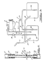
- Fuel is introduced to the tank through fill pipe 6 which has branches 6a and 6b for filling volumes 2 and 4 respectively.
- Volume 2 is a primary fuel volume while volume 4 is a secondary fuel volume. Any desired number of secondary fuel volumes can be used with the equalizing system of the present invention.
- Fuel is withdrawn from primary fuel volume 2 by fuel pump 34 which is positioned within the primary volume. Pump 34 discharges fuel into fuel pipe 8 which extends between the fuel pump and fuel consuming device 10. In this case an internal combustion engine.
- fuel consuming device could be any type of engine or any other energy consuming machine supplied by a fuel system which circulates fuel between the machine and the fuel tank.
- fuel pump could be mounted on the engine as well.
- fuel returns from the engine to the fuel tank by way of fuel pipe 12.
- fuel pipe 12 Such an arrangement is commonly utilized with diesel engines and other sorts of engines including gasoline engines with fuel injection systems.
- Such engines typically circulate a relatively great volume of fuel continuously while utilizing only a small portion of the fuel and returning the balance to the tanks.
- the return flow through pipe 12 passes through venturi assembly 14 shown in detail in Figure 2.
- the venturi is sealed to fuel pipe 12 by means of rubber bushings 22 and 32.
- the fuel pipe is shown as being of metallic construction, other constructions are possible such as ferrous and nonferrous metals, plastics, various elastomers and other materials.
- Leading section 23 of venturi 14 is upstream of the low pressure section of the venturi and is attached directly to the fuel line by means of rubber bushing 22.
- Converging section 24 of venturi, which adjoins leading section 23, is characterized by the usual reduction in flow diameter found in a venturi.
- Low pressure connector 30 is mounted at throat 26, which marks the minimum diameter of the venturi.
- This connector comprises a short length of tubing fitted to a radial bore 31 formed in the venturi. Although metallic tubing is preferred for the connector, other materials could be utilized such as plastics, or composites.
- Diverging section 28 is located immediately downstream from throat 25 and adjoins trailing section 29 which is connected by means of rubber bushing 32 to the downstream side of fuel pipe 12.
- venturi 14 is illustrated as being in pipe 12, those skilled in the art will appreciate in view of this disclosure that the venturi could be positioned in the fuel pump's suction line. This is particularly so where fuel pump 34 is located at the engine or other fuel consuming device.
- fuel pump 34, venturi 14, and conduit 16 are shown in broken lines identified by numerals 34a, 14a, and 16a, respectively, in Figure 1.
- Low pressure connector 30 provides a source of vacuum for operating the syphon of the present invention because the flow through the venturi results in a low pressure at throat 26, which is tapped by low pressure connector.
- Connector 30 is attached to the first end, 15, of conduit 16 which has a second end, 17, attached to syphon 18 at the highest point of the syphon.
- Porous metal filter 20 is fitted to second end 17 of the conduit and functions to prevent contamination from entering conduit 16 and consequently plugging low pressure connection 30.
- filter media could be employed in addition to a porous metal element.
- Venturi assembly 14 is preferably injection molded of a plastic material such as nylon but other materials and methods of construction are possible, such as molding or casting of ferrous or nonferrous metals or other plastic compositions or machining of the venturi assembly from any of these materials.
- Syphon 18 extends between the lower portion of primary fuel volume 2 and the lower portion of secondary fuel volume 4. As shown in Figure 1, leg 18a of syphon 18 extends into fuel volume 2 whereas leg 18b of syphon 18 extends into fuel volume 4.
- fuel pump 34 sends fuel continuously through fuel pipe 8 to the engine and fuel returns continuously through fuel pipe 12 through venturi 14 and then into primary fuel volume 2.
- the flow of fuel through venturi assembly 14 produces a low pressure at throat 26 which is communicated to conduit 16 by means of low pressure connector 30.
- Conduit 16 may comprise a rubber tube or a metallic or plastic tube depending upon the choice of the designer.
- the low pressure condition at the throat of the venturi communicated by low pressure connector 30 and conduit 16 to syphon 18 causes any air within syphon 18 to be purged through conduit 16 along with a quantity of liquid fuel which will join the stream within fuel pipe 12. Simultaneously, syphon action will be started between secondary fuel volume 4 and primary fuel volume 2. This syphoning action will be continuous and will automatically cause the level of fuel within the primary and secondary fuel volumes to be equalized because fuel consumed from volume 2 will be replaced by fuel from volume 4. This equalization occurs without the intervention of any solenoid or valve switching or intervention by the vehicle operator and requires only that the engine be operated so as to establish a flow of fuel through fuel pipe 12 and venturi assembly 14. Because no connection is required between the lower extremities of the fuel volumes in addition to that provided by the syphon, other machinery such as an automotive driveshaft or exhaust pipe could be located between the fuel volumes without interferring therewith.
- Figure 3 illustrates a second embodiment of the present invention in which a low pressure region is formed between flow restrictor 36, which is applied to the inlet of fuel pipe 8, and inlet 40 to fuel pump 34.
- Low pressure connector 38 is attached to fuel pipe 8 between flow restrictor 36 and pump inlet 40.
- the flow restrictor preferably comprises an orifice which is sized such that the progression of fuel through the orifice will be obstructed to a degree that a low pressure region will be formed between the restrictor and the inlet to the fuel pump, but without excessive restriction which would starve the engine for fuel.
- the low pressure connector is attached to the first end, 15, of conduit 16, which has a second end, 17, attached to syphon 18 at the highest point of the syphon. As before, syphon 18 has two ends, 18A and 18B extending into fuel volumes 2 and 4, respectively.
- the system of Figure 3 operates to equalize the level of fuel within volumes 2 and 4 as follows.
- fuel is pumped to engine 10 by means of fuel pump 34, which is connected to fuel volume 2 by fuel pipe 8.
- Flow restrictor 36 causes a pressure depression within the section of fuel pipe 8 extending between flow restrictor 36 and fuel pump inlet 40. This depression is communicated to syphon 18 by means of conduit 16 and low pressure connection 38.
- syphon 18 draws fuel from volume 4 into volume 2 to replace fuel consumed by engine 10.
Landscapes
- Engineering & Computer Science (AREA)
- Chemical & Material Sciences (AREA)
- Combustion & Propulsion (AREA)
- Mechanical Engineering (AREA)
- General Engineering & Computer Science (AREA)
- Cooling, Air Intake And Gas Exhaust, And Fuel Tank Arrangements In Propulsion Units (AREA)
Applications Claiming Priority (2)
| Application Number | Priority Date | Filing Date | Title |
|---|---|---|---|
| US81336485A | 1985-12-24 | 1985-12-24 | |
| US813364 | 1985-12-24 |
Publications (2)
| Publication Number | Publication Date |
|---|---|
| EP0228176A1 true EP0228176A1 (fr) | 1987-07-08 |
| EP0228176B1 EP0228176B1 (fr) | 1990-11-14 |
Family
ID=25212172
Family Applications (1)
| Application Number | Title | Priority Date | Filing Date |
|---|---|---|---|
| EP86308917A Expired - Lifetime EP0228176B1 (fr) | 1985-12-24 | 1986-11-14 | Système d'équilibrage pour réservoir de carburant |
Country Status (5)
| Country | Link |
|---|---|
| EP (1) | EP0228176B1 (fr) |
| JP (1) | JPS62159761A (fr) |
| CA (1) | CA1269288A (fr) |
| DE (1) | DE3675640D1 (fr) |
| ES (1) | ES2019064B3 (fr) |
Cited By (10)
| Publication number | Priority date | Publication date | Assignee | Title |
|---|---|---|---|---|
| FR2665731A1 (fr) * | 1990-08-13 | 1992-02-14 | Sullair Corp | Systeme d'alimentation en fluide notamment pour equipement mobile a moteur. |
| GB2274435A (en) * | 1993-01-23 | 1994-07-27 | Daimler Benz Ag | Fuel tank system for motor vehicles. |
| US6436904B1 (en) | 1999-01-25 | 2002-08-20 | Elan Pharmaceuticals, Inc. | Compounds which inhibit leukocyte adhesion mediated by VLA-4 |
| US6607005B2 (en) | 2000-11-08 | 2003-08-19 | Kautex Textron Gmbh & Co. Kg | Fuel tank |
| WO2008105721A1 (fr) * | 2007-02-26 | 2008-09-04 | Scania Cv Ab | Agencement de réservoir à carburant pour un véhicule |
| WO2010064972A1 (fr) * | 2008-12-05 | 2010-06-10 | Scania Cv Ab | Agencement pour transférer du carburant d’un ou de plusieurs réservoirs secondaires à un réservoir principal |
| WO2011071440A1 (fr) * | 2009-12-08 | 2011-06-16 | Scania Cv Ab | Agencement pour alimentation en combustible d'un moteur |
| EP2783938A1 (fr) * | 2013-03-29 | 2014-10-01 | ALSTOM Transport SA | Alimentation et stockage de carburant embarqués dans un véhicule ferroviaire |
| CN107215204A (zh) * | 2017-07-24 | 2017-09-29 | 江铃汽车股份有限公司 | 汽车双油箱连通结构 |
| EP3636477A1 (fr) * | 2018-10-11 | 2020-04-15 | Albert Ziegler GmbH | Dispositif comprenant une pompe, moteur à combustion interne destiné à actionner la pompe et réservoir de carburant |
Families Citing this family (4)
| Publication number | Priority date | Publication date | Assignee | Title |
|---|---|---|---|---|
| JPH0280764U (fr) * | 1988-12-09 | 1990-06-21 | ||
| US5979485A (en) * | 1996-07-01 | 1999-11-09 | Walbro Corporation | Fuel tank level equalizer system |
| US6845782B2 (en) | 2002-10-11 | 2005-01-25 | International Truck Intellectual Property Company, Llc | Multiple tank circulating fuel system |
| JP5133093B2 (ja) * | 2008-03-06 | 2013-01-30 | 本田技研工業株式会社 | 鞍型燃料タンク |
Citations (4)
| Publication number | Priority date | Publication date | Assignee | Title |
|---|---|---|---|---|
| US2703607A (en) * | 1949-03-25 | 1955-03-08 | Milo R Simmonds | Multiple cell fuel tank arrangement |
| US3021855A (en) * | 1958-03-10 | 1962-02-20 | Theodore R Cartwright | Self-motivating automatic syphoning and equalizing tank system |
| GB1581978A (en) * | 1978-02-03 | 1980-12-31 | Bosch Gmbh Robert | Fuel system for an internal combustion engine |
| GB2124703A (en) * | 1982-08-03 | 1984-02-22 | Lucas Ind Plc | Fuel supply system for an internal combustion engine |
-
1986
- 1986-11-14 EP EP86308917A patent/EP0228176B1/fr not_active Expired - Lifetime
- 1986-11-14 DE DE8686308917T patent/DE3675640D1/de not_active Expired - Lifetime
- 1986-11-14 ES ES86308917T patent/ES2019064B3/es not_active Expired - Lifetime
- 1986-11-20 CA CA000523459A patent/CA1269288A/fr not_active Expired - Lifetime
- 1986-12-23 JP JP61307602A patent/JPS62159761A/ja active Pending
Patent Citations (4)
| Publication number | Priority date | Publication date | Assignee | Title |
|---|---|---|---|---|
| US2703607A (en) * | 1949-03-25 | 1955-03-08 | Milo R Simmonds | Multiple cell fuel tank arrangement |
| US3021855A (en) * | 1958-03-10 | 1962-02-20 | Theodore R Cartwright | Self-motivating automatic syphoning and equalizing tank system |
| GB1581978A (en) * | 1978-02-03 | 1980-12-31 | Bosch Gmbh Robert | Fuel system for an internal combustion engine |
| GB2124703A (en) * | 1982-08-03 | 1984-02-22 | Lucas Ind Plc | Fuel supply system for an internal combustion engine |
Cited By (19)
| Publication number | Priority date | Publication date | Assignee | Title |
|---|---|---|---|---|
| FR2665731A1 (fr) * | 1990-08-13 | 1992-02-14 | Sullair Corp | Systeme d'alimentation en fluide notamment pour equipement mobile a moteur. |
| GB2274435A (en) * | 1993-01-23 | 1994-07-27 | Daimler Benz Ag | Fuel tank system for motor vehicles. |
| DE4301762A1 (de) * | 1993-01-23 | 1994-07-28 | Daimler Benz Ag | Tanksystem |
| FR2702714A1 (fr) * | 1993-01-23 | 1994-09-23 | Daimler Benz Ag | Système de réservoir de carburant en au moins deux parties reliées par un déversoir, en particulier pour véhicules automobiles. |
| GB2274435B (en) * | 1993-01-23 | 1996-01-03 | Daimler Benz Ag | A fuel tank system |
| ES2089964A2 (es) * | 1993-01-23 | 1996-10-01 | Daimler Benz Ag | Sistema de deposito |
| US6949570B2 (en) | 1999-01-25 | 2005-09-27 | Elan Pharmaceuticals, Inc. | Compounds which inhibit leukocyte adhesion mediated by VLA-4 |
| US6436904B1 (en) | 1999-01-25 | 2002-08-20 | Elan Pharmaceuticals, Inc. | Compounds which inhibit leukocyte adhesion mediated by VLA-4 |
| US6607005B2 (en) | 2000-11-08 | 2003-08-19 | Kautex Textron Gmbh & Co. Kg | Fuel tank |
| WO2008105721A1 (fr) * | 2007-02-26 | 2008-09-04 | Scania Cv Ab | Agencement de réservoir à carburant pour un véhicule |
| EP2121368A1 (fr) * | 2007-02-26 | 2009-11-25 | Scania CV AB | Agencement de réservoir à carburant pour un véhicule |
| EP2121368A4 (fr) * | 2007-02-26 | 2011-02-16 | Scania Cv Ab | Agencement de réservoir à carburant pour un véhicule |
| WO2010064972A1 (fr) * | 2008-12-05 | 2010-06-10 | Scania Cv Ab | Agencement pour transférer du carburant d’un ou de plusieurs réservoirs secondaires à un réservoir principal |
| WO2011071440A1 (fr) * | 2009-12-08 | 2011-06-16 | Scania Cv Ab | Agencement pour alimentation en combustible d'un moteur |
| RU2501671C1 (ru) * | 2009-12-08 | 2013-12-20 | Сканиа Св Аб | Устройство для подачи топлива в двигатель |
| EP2783938A1 (fr) * | 2013-03-29 | 2014-10-01 | ALSTOM Transport SA | Alimentation et stockage de carburant embarqués dans un véhicule ferroviaire |
| US9580083B2 (en) | 2013-03-29 | 2017-02-28 | Alstom Transport Technologies | On board fuel storage and supply in a rail vehicle |
| CN107215204A (zh) * | 2017-07-24 | 2017-09-29 | 江铃汽车股份有限公司 | 汽车双油箱连通结构 |
| EP3636477A1 (fr) * | 2018-10-11 | 2020-04-15 | Albert Ziegler GmbH | Dispositif comprenant une pompe, moteur à combustion interne destiné à actionner la pompe et réservoir de carburant |
Also Published As
| Publication number | Publication date |
|---|---|
| ES2019064B3 (es) | 1991-06-01 |
| CA1269288A (fr) | 1990-05-22 |
| JPS62159761A (ja) | 1987-07-15 |
| EP0228176B1 (fr) | 1990-11-14 |
| DE3675640D1 (de) | 1990-12-20 |
Similar Documents
| Publication | Publication Date | Title |
|---|---|---|
| EP0228176B1 (fr) | Système d'équilibrage pour réservoir de carburant | |
| US6276342B1 (en) | Fuel supply system | |
| US7069913B1 (en) | Fuel delivery system for a combustion engine | |
| EP1122423B1 (fr) | Module d'acheminement de carburant pour réservoir bifurqués de véhicule | |
| US6371153B1 (en) | Dual fuel delivery module system for multi-chambered or multiple automotive fuel tanks | |
| US4491117A (en) | Apparatus for supplying cooled fuel to an engine | |
| US6871640B2 (en) | Saddle tank siphon primer | |
| US20070128049A1 (en) | Jet pump apparatus for a vehicle fuel tank | |
| US5941279A (en) | Fuel container | |
| EP0690219B1 (fr) | Système d'alimentation en combustible | |
| JPH05288028A (ja) | 車両用エンジンの潤滑油供給装置 | |
| CN208718814U (zh) | 一种燃油泵总成的汽油压力调节器降噪结构 | |
| US3101771A (en) | Liquid fuel system for vehicles | |
| CN1914416B (zh) | 用于燃油供给模块的联结阀结构 | |
| US6460562B1 (en) | Dual tank simultaneous fill system | |
| US3841613A (en) | Fuel metering device for internal combustion engines | |
| GB1178598A (en) | Improvements in or relating to Fuel Supply Systems for Engines | |
| US3083720A (en) | Self-motivating automatic siphoning and equalizing tank system | |
| EP0863304B1 (fr) | Unité d'admission et de refoulement de carburant, notamment pour véhicules automobiles | |
| JP2508693B2 (ja) | 車両用燃料供給装置 | |
| JPS63170120A (ja) | エンジンと無関係の車両暖房装置の燃料供給装置 | |
| GB2274435A (en) | Fuel tank system for motor vehicles. | |
| US20210260500A1 (en) | Continuous Flow System For Draining Fuel-Water Separator | |
| CN214273842U (zh) | 一种适配高速船艇的燃油管路系统 | |
| CN219865294U (zh) | 双泵供油系统 |
Legal Events
| Date | Code | Title | Description |
|---|---|---|---|
| PUAI | Public reference made under article 153(3) epc to a published international application that has entered the european phase |
Free format text: ORIGINAL CODE: 0009012 |
|
| AK | Designated contracting states |
Kind code of ref document: A1 Designated state(s): DE ES FR GB |
|
| 17P | Request for examination filed |
Effective date: 19880119 |
|
| 17Q | First examination report despatched |
Effective date: 19880511 |
|
| GRAA | (expected) grant |
Free format text: ORIGINAL CODE: 0009210 |
|
| AK | Designated contracting states |
Kind code of ref document: B1 Designated state(s): DE ES FR GB |
|
| REF | Corresponds to: |
Ref document number: 3675640 Country of ref document: DE Date of ref document: 19901220 |
|
| ET | Fr: translation filed | ||
| PLBE | No opposition filed within time limit |
Free format text: ORIGINAL CODE: 0009261 |
|
| STAA | Information on the status of an ep patent application or granted ep patent |
Free format text: STATUS: NO OPPOSITION FILED WITHIN TIME LIMIT |
|
| REG | Reference to a national code |
Ref country code: GB Ref legal event code: 746 |
|
| 26N | No opposition filed | ||
| PGFP | Annual fee paid to national office [announced via postgrant information from national office to epo] |
Ref country code: ES Payment date: 19911119 Year of fee payment: 6 |
|
| REG | Reference to a national code |
Ref country code: FR Ref legal event code: DL |
|
| PG25 | Lapsed in a contracting state [announced via postgrant information from national office to epo] |
Ref country code: ES Free format text: LAPSE BECAUSE OF THE APPLICANT RENOUNCES Effective date: 19921116 |
|
| PGFP | Annual fee paid to national office [announced via postgrant information from national office to epo] |
Ref country code: GB Payment date: 19941027 Year of fee payment: 9 |
|
| PGFP | Annual fee paid to national office [announced via postgrant information from national office to epo] |
Ref country code: DE Payment date: 19941122 Year of fee payment: 9 |
|
| PGFP | Annual fee paid to national office [announced via postgrant information from national office to epo] |
Ref country code: FR Payment date: 19941223 Year of fee payment: 9 |
|
| PG25 | Lapsed in a contracting state [announced via postgrant information from national office to epo] |
Ref country code: DE Effective date: 19951010 |
|
| PG25 | Lapsed in a contracting state [announced via postgrant information from national office to epo] |
Ref country code: GB Effective date: 19951114 |
|
| GBPC | Gb: european patent ceased through non-payment of renewal fee |
Effective date: 19951114 |
|
| PG25 | Lapsed in a contracting state [announced via postgrant information from national office to epo] |
Ref country code: FR Effective date: 19960731 |
|
| REG | Reference to a national code |
Ref country code: FR Ref legal event code: ST |
|
| REG | Reference to a national code |
Ref country code: ES Ref legal event code: FD2A Effective date: 20010402 |