EP0226237A1 - Pole-pointing and/or cutting apparatus - Google Patents
Pole-pointing and/or cutting apparatus Download PDFInfo
- Publication number
- EP0226237A1 EP0226237A1 EP86201984A EP86201984A EP0226237A1 EP 0226237 A1 EP0226237 A1 EP 0226237A1 EP 86201984 A EP86201984 A EP 86201984A EP 86201984 A EP86201984 A EP 86201984A EP 0226237 A1 EP0226237 A1 EP 0226237A1
- Authority
- EP
- European Patent Office
- Prior art keywords
- pile
- piles
- milling
- hold
- frame
- Prior art date
- Legal status (The legal status is an assumption and is not a legal conclusion. Google has not performed a legal analysis and makes no representation as to the accuracy of the status listed.)
- Withdrawn
Links
Images


Classifications
-
- B—PERFORMING OPERATIONS; TRANSPORTING
- B23—MACHINE TOOLS; METAL-WORKING NOT OTHERWISE PROVIDED FOR
- B23Q—DETAILS, COMPONENTS, OR ACCESSORIES FOR MACHINE TOOLS, e.g. ARRANGEMENTS FOR COPYING OR CONTROLLING; MACHINE TOOLS IN GENERAL CHARACTERISED BY THE CONSTRUCTION OF PARTICULAR DETAILS OR COMPONENTS; COMBINATIONS OR ASSOCIATIONS OF METAL-WORKING MACHINES, NOT DIRECTED TO A PARTICULAR RESULT
- B23Q7/00—Arrangements for handling work specially combined with or arranged in, or specially adapted for use in connection with, machine tools, e.g. for conveying, loading, positioning, discharging, sorting
- B23Q7/03—Arrangements for handling work specially combined with or arranged in, or specially adapted for use in connection with, machine tools, e.g. for conveying, loading, positioning, discharging, sorting by means of endless chain conveyors
-
- B—PERFORMING OPERATIONS; TRANSPORTING
- B27—WORKING OR PRESERVING WOOD OR SIMILAR MATERIAL; NAILING OR STAPLING MACHINES IN GENERAL
- B27M—WORKING OF WOOD NOT PROVIDED FOR IN SUBCLASSES B27B - B27L; MANUFACTURE OF SPECIFIC WOODEN ARTICLES
- B27M3/00—Manufacture or reconditioning of specific semi-finished or finished articles
- B27M3/32—Manufacture or reconditioning of specific semi-finished or finished articles of tapered poles, e.g. mine props
Definitions
- the invention relates to a device for tapering and / or folding round piles.
- Devices of this type are known, inter alia from European patent application 0.066.368.
- the pile to be pointed is guided axially into the machine and then provided with a multi-surface point by a relative axial feed movement of the cutting edges relative to the pile.
- the machine can only work step-by-step, and after each sharpening operation, the pile must be axially removed from the machine and the next pile inserted.
- An additional disadvantage of the machine can be that the wooden parts removed during sharpening are coarse and not yet chipped into small pieces, as is often required for a useful use of the waste wood in, for example, chipboard to be produced therefrom. During the sharpening process, the pile stands still at this facility.
- the cutting device consists of a conical drum, as known from the hand-operated pencil sharpeners, wherein one or more cutting edges are driven in rotation via a conical jacket with an axis coinciding with the axis of the pile to be pointed.
- This device a mechanized sharpening machine, with the cutting drum rotating and the pile standing still and being axially inserted in the usual way in order to maintain the feed.
- This device also works step by step, so that after each sharpening process the pile must be axially removed before the next one can be inserted.
- the material removed during sharpening is planer-shaped and is also not suitable for processing into chipboard.
- the invention aims to provide a device which does not have the disadvantages mentioned above and which can be designed both as a step-by-step machine and as a continuously operating machine.
- the space requirement is not much longer than the length of the longest pile to be machined.
- the device according to the invention is characterized in that it contains. - an elongated frame, at least one transverse conveyor system arranged thereon, which is designed to give one or more piles carried in the longitudinal direction both a feed movement in the transverse direction with respect to the elongated frame and a rotation about its axis, - At least one rotatably driven milling cutter fastened to the frame, the axis of rotation of which is at an angle to the direction of the axis of a pile, if this has been brought into the working area of the milling cutter by the transverse conveyor system, which angle is a component with respect to both the horizontal and the vertical Plane may have, the effective area of the cutting surface of the milling machine height is adjustable in relation to the plane in which the transverse adjustment of the pile takes place, and the position of the milling cutter (the milling) can be adjusted in the longitudinal direction of the frame to adapt to the pile length.
- the described device is primarily intended for the processing of round piles.
- the starting product a tree
- the wood is often impregnated, which is only possible if the tree trunk has been peeled and thus debarked.
- the peeling process is based on round piles and also delivers round piles.
- additional processing steps are required, while wood loss also occurs. If, however, other than round piles need to be pointed and / or bevelled, then this can also be done with the device according to the invention if auxiliary tools are used at the points at which the pile is gripped by the cross conveyor system.
- articulated jaws can be used which, when closed, have an inner opening which fits exactly around the cross section of the pile and whose outer contour is cylindrical and has an axis coinciding with the axis of the pile. Thanks to the conveyor system described below, these jaws no longer need to be closed.
- the auxiliary tool should be attached or removed before and after processing such a pile.
- a rotating milling cutter near each end of the frame, the angle and possibly also the height of which can be adjusted individually with respect to the pile to be processed, so that a pile is either pointed or chamfered at one or both ends, or at can be sharpened at one end and folded at the other end.
- piles can be provided with both a point and a bevel at the same time. Because the tip often has an acute angle to the axis of the pile, but the bevel has an angle of 45 ° or greater, it is advantageous that the angle of each cutter can be adjusted individually. This also enables the production of piles with double bevels or, exceptionally, the production of piles with tips at both ends.
- a third rotating saw-mill unit can be fitted between the two cutters near the frame ends, in order to either bevel it between the ends of the post and saw through or sharpen it and, if necessary, saw through it, so that two short fully processed piles are formed.
- the cross conveyor system must be adapted to this. This is explained in more detail below. Further features and preferred embodiments of the milling cutter and its positioning are explained in more detail in the illustration description and in the patent claims. They are all designed to use simple standard milling machines that are easy to grind, deliver short chips and can apply a sufficiently smooth surface to the pile.
- the device more generally described above can be used for gradual tipping and / or folding of piles Be designed for piles, but also for continuous processing. This influences the execution of the cross conveyor system.
- a preferred embodiment of a device according to the invention, intended for step-by-step machining, is characterized in that the transverse conveyor system comprises a carriage guided transversely in the frame, with drive devices for a fast feed stroke, followed by a slow feed over the processing line and a fast return stroke over the entire Cross adjustment stroke.
- This movement cycle for the cross conveyor system is advantageous if the loading and unloading of the device with one pile occurs only on one side of the device. This can be done both manually and mechanically. It should be noted that with the same device, a different step-by-step cycle is also possible, the loading being carried out with a pile on one side, after which the processing and then the unloading take place on the other longitudinal side of the device during the transverse adjustment.
- a new pile is then loaded on this other side, which is passed through the milling section, so that the trolley reaches the first side again, in order to then hand over the processed pile and be loaded with a new pile.
- the piles pass the milling cutters, so that the milling cutters should preferably be installed above or possibly below the piles.
- the preferred construction is characterized in that at least two pairs of synchronously rotating driven support rollers for rotating support of the pile are attached to the carriage, each pair in the vicinity he router at the end of the frame, the spacing of the support rollers of each pair from each other being adjustable as a function of the thickness of the pile to be machined, and all rollers in the same direction synchronously by means of a chain gear or the like in each pair and an axially extendable cardan shaft or the like be driven between the pairs.
- the device is characterized in that a stationary hold-down device is mounted on the frame vertically above each pair of support rollers, which only covers the area of the transverse movement on which the pile is milled, which hold-down device each has two freely rotating discs with the Rotation axis includes parallel to the pile axis, and which are both located in the vertical plane by the associated pair of support rollers, and the axes of the hold-down disks are at least at a distance corresponding to the milling distance and a belt, for example a V-belt, over the two disks of each pair is taut, wherein each hold-down device is articulated to the frame about a horizontal axis parallel to the axis of the pile at a distance from the milling path and approximately at the height of the pile and is pressed down by an elastic hold-down device to an adjustable stop, the distance at rest between the top of the Support rollers and the underside of the hold-down discs is slightly less than the thickness of the pile, all
- the device is preferably provided with an additional pair of support rollers with an associated hold-down device on both sides of the third or middle saw-milling unit.
- the two remaining short piles will also have to remain securely supported.
- the cross conveyor system must be suitable for this.
- the device is characterized in that the effective area of the cutting surface of each milling cutter is preferably above (or possibly below) the plane in which the transverse adjustment of this pile takes place, that the cross conveyor system consists of at least two endless, tensioned conveyor chains or the like, which is parallel to each other and perpendicular in the vertical plane the axis of the piles are mounted on the frame with diversion wheels and are to be driven synchronously, the upper part carrying the piles in operation, and that an endless tensioned hold-down chain is attached above each conveyor chain in the same vertical plane and is mounted on the frame with diversion wheels in a height-adjustable manner and with its lower part presses down the piles and runs parallel to the upper part of the associated conveyor chain, and both hold-down chains can be driven synchronously.
- Known devices can be used for this, which need not be described further. But it is also necessary that during the cross-conveying and especially during the milling process the piles in question maintain their path with the conveyor chain despite the sometimes great forces exerted on them.
- the invention according to one Preferred embodiment characterized in that in operation the upper part of each conveyor chain with a speed
- the relationship between the circumferential speed of the pile and the feed speed results from the formulas.
- the installed capacity for the cross conveyor systems and especially for the milling machines should be coordinated. In view of the stable position of the piles and the avoidance of vibrations, it will be desirable in many cases to have the milling machine rotate in a direction opposite to the direction of rotation of the piles.
- the distance between the cross conveyor chains and the associated hold-down chains is adjustable in such a way that this is adapted to the diameter of the piles to be milled.
- piles to be machined in succession have relatively large differences in diameter; as an example here: for piles with a diameter of 10 cm up to 5 mm diameter difference. So that all piles are still firmly clamped between the tensioned conveyor and hold-down chains in the milling section, it is advantageous to push the lower part of the hold-down chain down by a series of individual spring-loaded hold-down devices, while the upper part of the conveyor chain is now rigidly supported by a long skid becomes.
- a too tight hold-down chain could inhibit the function of the successive individual resilient hold-down devices. It is therefore advisable to provide the upper part of the hold-down chain with a resilient length compensation device, which generates a lower pretension in the chain than that which the individual hold-down means can exert on the lower part. Pneumatically operated power cylinders are preferably used for this.
- FIGs 1, 2 and 3 are discussed below at the same time. It should be noted that the illustrations represent everything only schematically and of the entire device only the parts essential for a good understanding. The device shown is intended for step-by-step operation from the operating side, which is the left side of the figures in Figures 1 and 3 and the lower side in Figure 2.
- the frame of the entire device is denoted by 1 and includes, among other things, solid horizontal bars 2 attached to both transverse sides at the top.
- Schematically illustrated rails or guides 3 are fastened to these bars, which serve to guide a carriage 4 by means of schematically represented wheels 5 can be moved back and forth on the frame in the transverse direction on the rails or guides 3.
- Two support rollers are rotatably mounted on the carriage, the distance between which can be adjusted in a manner not shown.
- the support rollers 6 are located in a vertical plane, perpendicular to the longitudinal direction of the device. They are provided on their circumference with fixed, friction-increasing linings 7, for example with solid rubber tires.
- a pile 8 to be machined is placed in the clamping of the rolls.
- the height of piles 8 with different diameters can be set such that the axis of the pile 8 will always be approximately in the same horizontal plane.
- at least one corresponding support roller combination is located near the other end of the device for good pile support.
- This pair of support rollers is also attached to the carriage 4 in a corresponding manner.
- At least the pile 8 should be pressed firmly onto the support rollers 6 so that the cutting forces exerted by the cutting devices to be discussed below can neither throw the pile away nor set it into vibration.
- a hold-down device 9 has been attached to the frame 1, specifically a hold-down device 9 for cooperation with a pair of support rollers 6.
- the hold-down device 9 consists of a taut belt which has been placed around rotatably spaced disks 11.
- the discs 11 are mounted in a known manner on an arm 12 which is articulated at 13 about a horizontal axis parallel to the longitudinal direction of the device via a support 14 on the frame 1.
- the hinge axis 13 is located approximately at the top of a pile 8 to be machined. In the position shown in FIG. 1, the rest position, the arm 12 rests on a stop 15 which can be adjusted in a manner not shown.
- the holding-down device 9 can be moved from the position shown thus hinge upwards, as indicated by arrow 18 and shown in Fig. 3.
- a strong leaf spring 16 By means of a strong leaf spring 16, the hold-down device 9 is pressed down over a friction-reducing cover 17, for example made of a PTFE, onto the stop 15 in the idle state and onto a pile 8 to be processed during operation (FIG. 3).
- the diagram is schematic in the figures 1 and 2 indicated the cutter 19, which is intended for sharpening the pile 8.
- the axis of the milling cutter 19 lies approximately in the same plane in which the axis of the pile 8 moves during the transverse adjustment of the carriage 4.
- the milling cutter 19 will be explained in more detail below.
- the support rollers 6 of each pair are driven synchronously with the same direction of rotation by means of, for example, a chain transmission 21 from an adjustable tensioning roller 23, which tensioning roller 23 in turn is driven by a motor 24 via a chain transmission 22.
- the latter is fastened to the carriage 4 with the tensioning roller 23.
- All pairs of support rollers of the device are driven continuously synchronously with one another by known means which are not specified.
- the drives can do this can be coupled between the individual pairs of support rollers by means of, for example, axially retractable and extendable cardan shafts 231, but the drive motors can also be electrically synchronized.
- the transverse drive of the carriage 4 is provided by a schematically illustrated hydraulic or pneumatic power cylinder 25, which is articulated to a chair 26, which in turn is arranged on one of the lower beams of the frame 1.
- the outgoing rod 27 of the cylinder 25 is articulated to a lever 28, 29, which is articulated between its ends on a chair 31, which in turn is also attached to the frame 1.
- the articulated mounting of the lever 28, 29 comprises an axis 30 which runs parallel to the longitudinal direction of the frame from one end to the other end and is mounted in the chair 31 near the ends. If the axis 30 has a sufficiently high torsional rigidity, the carriage 4 will be driven in exactly the same way near its two ends, starting from a single power cylinder 25.
- the lever 29 is again articulated via a rod 32 to a coupling 33 of the carriage 4.
- Operation of the power cylinder 25, which is double-acting in the figures, but can also be single-acting, in which case it should be provided with a return spring, ensures the transverse adjustment of the carriage 4.
- This is in Fig. 1 in the extreme position on the operating side of the entire facility, where machined piles 8 are removed and new ones are inserted. From the loading and unloading position of the carriage 4 shown in FIG. 1, the latter is adjusted to the right in the figures as a result of the extension of the power cylinder 25, 27, the pile 8 to be machined first approaching the holding-down device 9 and then the milling cutter 19.
- the linkage can be designed in the manner shown.
- the angle between the lever 29 and the connecting rod 32 is acute and passes through the 90 ° range, so that with constant extension of the cylinder 25, a high feed rate occurs. If the carriage comes into the processing area L (Fig.
- means not shown such as limit switches, can be used, which control the actuation of the power cylinder.
- somewhat resilient emergency stop stops can also be provided.
- a (not shown) (hydraulic) damper can further stabilize the feed movement on the milling path.
- the pile 8 is rotated on its support rollers 6 by the drive 21-24, and this drives the hold-down rollers 11 and the belt 10, which are exposed, as they rotate.
- the milling path is covered in about 2 seconds and the pile 8 makes about 10 revolutions.
- the frame 1 carries on its upper side a longitudinal beam 51 on the rear and a longitudinal beam 52 on the operating side.
- a cross frame 47, 48, 478 is adjustably fastened thereon to support the milling cutter 19 and its drive.
- This milling frame is slightly raised so that the carriage 4 is freely movable back and forth underneath. However, it is also of low height, so that the milling cutter 19 is at the desired height, and the pile 8 can be freely moved back and forth on the milling frame.
- the milling frame can be adjusted in the longitudinal direction on the main frame 1.
- slots 50 have been made in the horizontal bars 51 and 52, in which fasteners 49 are shown with schematically represented, easy-to-use fasteners the milling frame can be attached.
- the milling cutter 19, together with its drive motor 40 and its gear 41, is mounted on a turntable 44 in a solid, rotatable manner in a known manner, not shown.
- the turntable 44 is pivotable about axis 42 and can be fixed in different angular positions with respect to the milling frame by means of a slot 43 and a fastening means 431, for example bolts and clamping nuts, which pass through it.
- the axis of rotation of the milling cutter is adjusted with respect to the axis of the pile, so that the apex angle of the tip of the pile to be machined can be adjusted.
- the turntable 44 is in turn supported by a plate 45 which is adjustably fastened on the milling frame 47, 48, 478 by means of slots 46 and associated fastening means.
- the latter setting option 46 serves above all to be able to optimally adjust the milling machine when piles with a large diameter difference have to be pointed. At the same time, a different milling diameter can be compensated for, which can be a consequence of regrinding, for example.
- the milling cutter 19 must lie above the adjustment level of the piles 8, so that the piles can be adjusted underneath and can now be pointed and folded.
- the operating device of the carriage 4 will of course have to be adapted to this, while the support 14 of the holding-down device 9 must be changed in such a way that it does not inhibit loading and unloading on this side of the device. The required The position of the milling cutter 19 is explained in more detail below with the aid of FIGS. 4, 5 and 6.
- Fig. 4 shows schematically a top view of the device described with reference to Figures 1, 2 and 3.
- the pile 8 is supported in the manner described on the pairs of support rollers 6, 7.
- Each pair is arranged in the vicinity of one end of the pile to be milled.
- the milling cutter 19 already described for producing the tip 9 is shown.
- the cutter 191 for attaching the fold 82 to the other end of the pile is shown.
- This milling cutter 191 is arranged in such a way that a bevel 82 with the usual angle of approximately 45 ° -60 ° to the axis of the pile can be produced with only a small amount of material removal.
- stop beam 60 which extends parallel to the transverse adjustment direction of the carriage 4 and against which the piles are placed during loading and on which they remain during their complete feed movement.
- the router 191 could also be replaced with a router to make two-point piles, or vice versa, the router 19 could be replaced with a router 119 or moved to a position to also fold.
- the cross conveyor system now consists of at least two endless tensioned conveyor chains, which are mounted on the frame in a known manner in the vertical plane parallel to one another and perpendicular to the axis of the piles by means of diversion wheels 67, 68.
- the upper part 65 is supported over its entire length by a runner 69 which is firmly supported on the frame by suitable supports 70.
- the hold-down chain 61, 62 is stretched around diversion rollers 63 and 64.
- the series of piles 84-89 to be machined is clamped and moved.
- Fig. 5c schematically shows the movement system, which will be discussed in more detail below.
- the milling cutter 19 In view of easy accessibility for exchanging and / or grinding the milling cutter 19, it is arranged essentially above the pile track.
- the bearings and the drive are in the drawings omitted, they basically agree with those described in Figures 1-3.
- the axis of rotation 20 of the milling cutter 19 is in any case at an angle ⁇ to the axis of the piles according to FIG. 5b, so that a tip 81 is milled on the piles.
- the milling cutter can be set higher than the pile length in order to obtain the blunt tip 83 indicated by a dotted line, which can be advantageous if the piles have to be driven into stony ground or the like.
- the apex angle of the pile tip is set by setting the angle ⁇ . In Fig.
- the axis 20 of the milling machine can also have an angle ⁇ to the axis of the piles in order to distribute the effective milling section L over several piles at the same time, so that the milling forces exerted on the pile are smaller and the milling load is more constant and the cutting direction will go more with the grain.
- the milling path shown in the figures corresponds to L.
- the piles 84, 85 and 86 are thus subjected to milling in this snapshot and should therefore be clamped sufficiently firmly between the conveyor belt and the hold-down belt.
- the straps are provided on their load-bearing side with fine sharp serrations or the like, as indicated schematically with 651, in order to grip the piles non-slip nonetheless without any significant damage to the pile surface.
- the piles rotate about their own axis during their feed movement under the milling machine.
- the upper part 65 of the conveyor belt with a linear speed
- the circumferential speed at which the pile rotates is approximately the same as
- is small and is: To mill the average spruce wood pile, each pile makes about 10 revolutions on the milling section L and covers this section in about 2 seconds. It follows from the above that the cooperating conveyor and hold-down belt are driven individually with the same direction of rotation for the diversion rollers 63, 64 and 67, 68, but with a slightly different value, in order to achieve a resulting feed rate
- Resilient sliding shoes are suitable for this. They are based on a frame part schematically indicated with 71 with sufficient strength, which is height-adjustable with the entire hold-down band, as indicated schematically with h. On the milling section L, however, the piles, in this case 84, 85 and 86 individually, should be firmly pressed on.
- hydraulically or pneumatically operated power cylinders 73 can be used, which exert such a hold-down force that they can overcome the pretension of the hold-down chain. In this way, piles of different thicknesses lying next to each other can be reliably controlled during the milling process, both in terms of their own rotation and in terms of their feed.
- Milling with long cutting edges that form wood shavings are less suitable, because of their greater sensitivity to knots in wood, for example. It will also be clear to the person skilled in the art that correct, right-angled feeding of the piles to the conveyor chain is required, but various known devices must be used for this purpose, which therefore need not be described and illustrated. In the manner already described, the continuous device can also be designed to make longer piles into two shorter ones.
Abstract
Description
Die Erfindung betrifft eine Einrichtung zum Anspitzen und/oder Abkanten runder Pfähle. Einrichtungen dieser Art sind bekannt, unter anderem aus der Europäischen Patentanmeldung 0.066.368. Bei dieser Einrichtung wird der anzuspitzende Pfahl axial in die Maschine geführt und danach durch eine relative axiale Vorschubbewegung der Schneiden gegenüber dem Pfahl mit einer mehrflächigen Spitze versehen. Die Maschine kann ausschließlich schrittweise arbeiten, und nach jedem vollendeten Anspitzvorgang muß der Pfahl axial aus der Maschine entfernt und der nächste Pfahl eingeführt werden. Ein hinzukommender Nachteil der Maschine kann sein, daß die beim Anspitzen entfernten Holzteile grob und noch nicht zu kleinen Stücken verspant sind, wie dies oft für einen nützlichen Gebrauch des Abfallholzes in beispielsweise daraus herzustellender Spanplatte erforderlich ist. Während des Anspitzvorgangs steht der Pfahl bei dieser Einrichtung still.The invention relates to a device for tapering and / or folding round piles. Devices of this type are known, inter alia from European patent application 0.066.368. In this device, the pile to be pointed is guided axially into the machine and then provided with a multi-surface point by a relative axial feed movement of the cutting edges relative to the pile. The machine can only work step-by-step, and after each sharpening operation, the pile must be axially removed from the machine and the next pile inserted. An additional disadvantage of the machine can be that the wooden parts removed during sharpening are coarse and not yet chipped into small pieces, as is often required for a useful use of the waste wood in, for example, chipboard to be produced therefrom. During the sharpening process, the pile stands still at this facility.
Aus der niederländischen Patentanmeldung 7406810 ist eine Einrichtung bekannt, bei der der anzuspitzende Pfahl ebenfalls axial eingeführt und beim Anspitzen axial vorgeschoben wird, wobei der Pfahl gegenüber der Einrichtung nicht rotieren soll. Die Schneideinrichtung besteht aus einer kegelförmigen Trommel, wie bei den handbedienten Bleistiftspitzern bekannt, wobei eine oder mehrere Schneiden rotierend über einen Kegelmantel mit mit der Achse des anzuspitzenden Pfahls zusammenfallender Achse angetrieben werden. Man könnte diese Einrichtung als mechanisierte Anspitzmaschine bezeichnen, wobei die Schneidtrommel dreht und der Pfahl stillsteht und auf übliche Weise axial eingesteckt wird, um den Vorschub zu erhalten. Auch diese Einrichtung funktioniert schrittweise, so daß nach jedem Anspitzvorgang der Pfahl axial entfernt werden muß, bevor der nächste eingeführt werden kann. Das beim Anspitzen entfernte Material ist hobelspanförmig und ebenfalls nicht ohne weiteres für Verarbeitung zu Spanplatten geeignet.From the Dutch patent application 7406810 a device is known in which the pile to be pointed is also inserted axially and is advanced axially when pointed, the pile not supposed to rotate relative to the device. The cutting device consists of a conical drum, as known from the hand-operated pencil sharpeners, wherein one or more cutting edges are driven in rotation via a conical jacket with an axis coinciding with the axis of the pile to be pointed. One could call this device a mechanized sharpening machine, with the cutting drum rotating and the pile standing still and being axially inserted in the usual way in order to maintain the feed. This device also works step by step, so that after each sharpening process the pile must be axially removed before the next one can be inserted. The material removed during sharpening is planer-shaped and is also not suitable for processing into chipboard.
Beide oben beschriebenen bekannten Einrichtungen haben darüberhinaus den Nachteil, daß sie verhältnismäßig viel Raum beanspruchen, weil die zu bearbeitenden Pfähle axial eingeführt und abgeführt werden müssen.Both known devices described above also have the disadvantage that they take up a relatively large amount of space because the piles to be machined have to be inserted and removed axially.
Die Erfindung bezweckt die Schaffung einer Einrichtung, die die obenerwähnten Nachteile nicht hat und die sowohl als schrittweise funktionierende Maschine wie auch als kontinuierlich funktionierende Maschine ausgeführt sein kann. Der erforderliche Raumbedarf ist nicht viel länger als die Länge des längsten zu bearbeitenden Pfahls.The invention aims to provide a device which does not have the disadvantages mentioned above and which can be designed both as a step-by-step machine and as a continuously operating machine. The space requirement is not much longer than the length of the longest pile to be machined.
Die erfindungsgemäße Einrichtung wird dadurch gekennzeichnet, daß sie enthält.
- einen länglichen Rahmen,
- wenigstens eine darauf angeordnete Querförderanlage, die dafür ausgelegt ist, einem oder mehreren in Längsrichtung darauf mitgenommenen Pfählen sowohl eine Vorschubbewegung in Querrichtung gegenüber dem länglichen Rahmen wie auch eine Rotation um seine/ihre Achse zu geben,
- wenigstens eine auf dem Rahmen befestigte rotierend angetriebene Fräse, deren Rotationsachse in einem Winkel zur Richtung der Achse eines Pfahls steht, wenn dieser durch die Querförderanlage in den Arbeitsbereich der Fräse gebracht worden ist, welcher Winkel eine Komponente sowohl gegenüber der waagerechten wie gegenüber der senkrechten Ebene haben kann, wobei der wirksame Bereich der Schnittfläche der Fräse hö henverstellbar gegenüber der Ebene ist, in der Querverstellung des Pfahls stattfindet, und wobei die Position der Fräse (der Fräsen) in Längsrichtung des Rahmens zur Anpassung an die Pfahllänge einstellbar ist.The device according to the invention is characterized in that it contains.
- an elongated frame,
at least one transverse conveyor system arranged thereon, which is designed to give one or more piles carried in the longitudinal direction both a feed movement in the transverse direction with respect to the elongated frame and a rotation about its axis,
- At least one rotatably driven milling cutter fastened to the frame, the axis of rotation of which is at an angle to the direction of the axis of a pile, if this has been brought into the working area of the milling cutter by the transverse conveyor system, which angle is a component with respect to both the horizontal and the vertical Plane may have, the effective area of the cutting surface of the milling machine height is adjustable in relation to the plane in which the transverse adjustment of the pile takes place, and the position of the milling cutter (the milling) can be adjusted in the longitudinal direction of the frame to adapt to the pile length.
Die beschriebene Einrichtung ist in allererster Linie für die Bearbeitung runder Pfähle gedacht. Das Ausgangsprodukt, ein Baum, hat ja ebenfalls einen runden Stamm. Um die Lebensdauer der Pfähle zu verlängern, wird das Holz oft imprägniert, was nur gut möglich ist, wenn der Baumstamm vorher geschält und somit entrindet worden ist. Das Schälverfahren geht von runden Pfählen aus und liefert auch runde Pfähle. Für alle anderen Pfahlquerschnitte, beispielsweise oval, quadratisch, rechteckig und ähnliche, sind zusätzliche Bearbeitungsgänge erforderlich, während außerdem Holzverlust eintritt. Sollten jedoch im Einzelfall andere als runde Pfähle angespitzt und/oder abgekantet werden müssen, dann kann dies ebenfalls mit der erfindungsgemäßen Einrichtung geschehen, wenn an den Stellen, an denen der Pfahl von der Querförderanlage gegriffen wird, Hilfswerkzeug eingesetzt wird. Dafür können gelenkige Backen angewandt werden, die in geschlossenem Zustand eine innere Öffnung haben, die genau um den Querschnitt des Pfahls paßt und deren Außenumriß zylindrisch ist und eine mit der Achse des Pfahls zusammenfallende Achse hat. Dank der weiter unten beschriebenen Förderanlage brauchen diese Backen nicht weiter geschlossen zu werden. Vor und nach der Bearbeitung eines solchen Pfahls soll das Hilfswerkzeug angebracht beziehungsweise abgenommen werden.The described device is primarily intended for the processing of round piles. The starting product, a tree, also has a round trunk. In order to extend the life of the piles, the wood is often impregnated, which is only possible if the tree trunk has been peeled and thus debarked. The peeling process is based on round piles and also delivers round piles. For all other pile cross-sections, for example oval, square, rectangular and the like, additional processing steps are required, while wood loss also occurs. If, however, other than round piles need to be pointed and / or bevelled, then this can also be done with the device according to the invention if auxiliary tools are used at the points at which the pile is gripped by the cross conveyor system. For this purpose, articulated jaws can be used which, when closed, have an inner opening which fits exactly around the cross section of the pile and whose outer contour is cylindrical and has an axis coinciding with the axis of the pile. Thanks to the conveyor system described below, these jaws no longer need to be closed. The auxiliary tool should be attached or removed before and after processing such a pile.
Indem sowohl der Pfahl wie die Fräse während des Fräsvorgangs ins Rotieren versetzt werden, entsteht eine einwandfreie runde Spitze und Abkantung an jedem Pfahl, ungeachtet seines Durchmessers. Durch Einstellung des Winkels, in dem die Rotationsachse der Fräse zum Pfahl steht, kann eine mehr oder weniger scharfe Spitze hergestellt werden. Durch richtige Einstellung der Fräse gegenüber dem anzuspitzenden Pfahlende kann ebenfalls einfach eine stumpfe Spitze hergestellt werden, wenn dies wegen der Bodenverhältnisse an der Stelle, an der der Pfahl eingesetzt werden soll, beispielsweise bei steinigem Boden, erforderlich sein sollte.By rotating both the pile and the milling cutter during the milling process, a perfect round tip and bevel is created on every pile, regardless of its diameter. By adjusting the angle at which the axis of rotation of the milling cutter is in relation to the pile, a more or less sharp point can be produced. By correctly setting the milling machine in relation to the end of the pile to be sharpened, a blunt tip can also be easily produced if this is due to the soil conditions at the point at which the Post should be used, for example on stony ground, should be necessary.
Nach einer Vorzugsausführungsform befindet sich in der Nähe jeden Endes des Rahmens eine rotierende Fräse, deren Winkel und eventuell auch Höhe individuell gegenüber dem zu bearbeitenden Pfahl eingestellt werden kann, so daß ein Pfahl entweder an einem oder an beiden Enden angespitzt oder abgekantet, oder aber an einem Ende angespitzt und am anderen Ende abgekantet werden kann. Damit können Pfähle gleichzeitig sowohl mit einer Spitze wie mit einer Abkantung versehen werden. Weil die Spitze oft einen spitzen Winkel zur Achse des Pfahls hat, die Abkantung jedoch einen Winkel von 45° oder größer, ist es vorteilhaft, daß der Winkel jeder Fräse einzeln eingestellt werden kann. Dies ermöglicht auch die Herstellung von Pfählen mit doppelter Abkantung oder ausnahmsweise die Fertigung von Pfählen mit Spitzen an beiden Enden.According to a preferred embodiment, there is a rotating milling cutter near each end of the frame, the angle and possibly also the height of which can be adjusted individually with respect to the pile to be processed, so that a pile is either pointed or chamfered at one or both ends, or at can be sharpened at one end and folded at the other end. This means that piles can be provided with both a point and a bevel at the same time. Because the tip often has an acute angle to the axis of the pile, but the bevel has an angle of 45 ° or greater, it is advantageous that the angle of each cutter can be adjusted individually. This also enables the production of piles with double bevels or, exceptionally, the production of piles with tips at both ends.
Weil die Position der Fräse(n) gegenüber dem Rahmen auch in Längsrichtung eingestellt werden kann, können auch kurze Pfähle bearbeitet werden. Sollte jedoch sehr viel langes Holz verfügbar sein, während kurze Pfähle verlangt werden, dann kann nach einer Vorzugsausführungsform zwischen den beiden Fräsen in der Nähe der Rahmenenden eine dritte rotierende Säge-Fräs-Einheit angebracht werden, um zwischen den Enden des Pfahls diesen entweder abzukanten und durchzusägen oder ihn anzuspitzen und erforderlichenfalls durchzusägen, so daß zwei kurze vollverarbeitete Pfähle entstehen. Es wird klar sein, daß die Querförderanlage dazu angepaßt werden muß. Dies wird unten näher erläutert. Weitere Merkmale und Vorzugsausführungsformen der Fräse und ihrer Positionierung sind näher in der Abbildungsbeschreibung und in den Patentansprüchen erläutert. Sie sind alle dafür ausgelegt, einfache Standardfräsen anzuwenden, die sich bequem schleifen lassen, kurze Späne abgeben und eine ausreichend glatt verarbeitete Oberfläche auf dem Pfahl anbringen können.Because the position of the milling cutter (s) in relation to the frame can also be adjusted in the longitudinal direction, short piles can also be machined. However, if there is a lot of long wood available, while short piles are required, then, according to a preferred embodiment, a third rotating saw-mill unit can be fitted between the two cutters near the frame ends, in order to either bevel it between the ends of the post and saw through or sharpen it and, if necessary, saw through it, so that two short fully processed piles are formed. It will be clear that the cross conveyor system must be adapted to this. This is explained in more detail below. Further features and preferred embodiments of the milling cutter and its positioning are explained in more detail in the illustration description and in the patent claims. They are all designed to use simple standard milling machines that are easy to grind, deliver short chips and can apply a sufficiently smooth surface to the pile.
Die oben mehr allgemein beschriebene Einrichtung kann für schrittweises Anspitzen und/oder Abkanten von Pfahl um Pfahl ausgelegt sein, aber auch für kontinuierliche Bearbeitung. Dies beeinflußt namentlich die Ausführung der Querförderanlage.The device more generally described above can be used for gradual tipping and / or folding of piles Be designed for piles, but also for continuous processing. This influences the execution of the cross conveyor system.
Von einer erfindungsgemäßen, für die schrittweise Bearbeitung bestimmten Einrichtung wird eine Vorzugsausführungsform dadurch gekennzeichnet, daß die Querförderanlage einen in Querrichtung im Rahmen geführten Wagen umfaßt, mit Antriebsvorrichtungen für einen schnellen Zufuhrhub, gefolgt von einem langsamen Vorschub über die Bearbeitungsstrecke und einem schnellen Rückhub über den gesamten Hub der Querverstellung. Dieser Bewegungszyklus für die Querförderanlage ist vorteilhaft, wenn die Beschickung und die Entladung der Einrichtung mit jeweils einem Pfahl nur auf einer der Seiten der Einrichtung geschieht. Dies kann sowohl von Hand wie auch mechanisiert erfolgen. Es sei darauf hingewiesen, daß mit derselben Einrichtung auch ein anderer schrittweiser Zyklus möglich ist, wobei die Beschickung mit einem Pfahl auf einer Seite erfolgt, wonach während der Querverstellung die Bearbeitung und dann die Entladung auf der anderen Längsseite der Einrichtung erfolgen. Danach wird auf dieser anderen Seite ein neuer Pfahl geladen, der durch die Frässtrecke geführt wird, so daß der Förderwagen wieder die erste Seite erreicht, um dort dann den bearbeiteten Pfahl abzugeben und mit einem neuen Pfahl beschickt zu werden. Bei der letzten Zyklusform passieren die Pfähle die Fräsen, so daß die Fräsen vorzugsweise über oder eventuell unter den Pfählen angebracht werden sollen. Bei der ersteren Zyklusform ist es möglich, die Fräsen etwa in der Ebene, in der die Querverstellung der Pfähle erfolgt, rotieren zu lassen, wofür es erforderlich ist, daß der Hub der Querverstellung am Schluß des Vorschubs im richtigen Augenblick gestoppt wird, nämlich, wenn die Spitze an dem Pfahl an der gewünschten Stelle an der Länge des Pfahls gefräst worden ist.A preferred embodiment of a device according to the invention, intended for step-by-step machining, is characterized in that the transverse conveyor system comprises a carriage guided transversely in the frame, with drive devices for a fast feed stroke, followed by a slow feed over the processing line and a fast return stroke over the entire Cross adjustment stroke. This movement cycle for the cross conveyor system is advantageous if the loading and unloading of the device with one pile occurs only on one side of the device. This can be done both manually and mechanically. It should be noted that with the same device, a different step-by-step cycle is also possible, the loading being carried out with a pile on one side, after which the processing and then the unloading take place on the other longitudinal side of the device during the transverse adjustment. A new pile is then loaded on this other side, which is passed through the milling section, so that the trolley reaches the first side again, in order to then hand over the processed pile and be loaded with a new pile. In the last cycle shape, the piles pass the milling cutters, so that the milling cutters should preferably be installed above or possibly below the piles. In the former cycle form, it is possible to rotate the milling cutters approximately in the plane in which the piles are transversely adjusted, for which it is necessary that the stroke of the transverse adjustment be stopped at the right moment at the end of the feed, namely if the tip on the post has been milled at the desired location along the length of the post.
Für die Rotation der Pfähle während der Querverstellung und namentlich über die Frässtrecke ist die Vorzugskonstruktion dadurch gekennzeichnet, daß auf dem Wagen wenigstens zwei synchron rotierend angetriebene Stützrollenpaare zur rotierenden Stützung des Pfahls angebracht sind, jedes Paar in der Nä he einer Fräse am Ende des Rahmens, wobei der Abstand der Stützrollen jeden Paars zueinander als Funktion der Dicke des zu bearbeitenden Pfahls einstellbar ist, und wobei alle Rollen in derselben Richtung synchron mittels eines Kettengetriebes oder dergleichen in jedem Paar und einer axial ausziehbaren Kardanwelle oder dergleichen zwischen den Paaren angetrieben werden.For the rotation of the piles during the transverse adjustment and especially over the milling section, the preferred construction is characterized in that at least two pairs of synchronously rotating driven support rollers for rotating support of the pile are attached to the carriage, each pair in the vicinity he router at the end of the frame, the spacing of the support rollers of each pair from each other being adjustable as a function of the thickness of the pile to be machined, and all rollers in the same direction synchronously by means of a chain gear or the like in each pair and an axially extendable cardan shaft or the like be driven between the pairs.
Vor allem wenn die zu bearbeitenden Pfähle verhältnismäßig leicht im Gewicht sind und die Bearbeitung schnell mit großer Leistung geschehen soll, und folglich große Fräskräfte auf die Pfahlenden ausgeübt werden, ist nicht sicher, daß die Pfähle durch ihr eigenes Gewicht sicher auf den Stützrollenpaaren liegen bleiben. Dazu wird nach einer weiteren Vorzugsausführungsform die Einrichtung dadurch gekennzeichnet, daß auf dem Rahmen senkrecht über jedem Stutzrollenpaar eine stationäre Niederhaltevorrichtung angebracht ist, die nur den Bereich der Querbewegung, auf dem der Pfahl gefräst wird, bestreicht, welche Niederhaltevorrichtung je zwei freidrehend gelagerte Scheiben mit der Rotationsachse parallel zur Pfahlachse umfaßt, und welche beide in der senkrechten Ebene durch das zugehörige Stützrollenpaar gelegen sind, und wobie die Achsen der Niederhaltescheiben wenigstens in einem mit der Frässtrecke übereinstimmenden Abstand voneinander entfernt sind und über die beiden Scheiben jeden Paars ein Riemen, beispielsweise ein Keilriemen, straff gespannt ist,
wobei jede Niederhaltevorrichtung um eine waagerechte Achse parallel zur Achse des Pfahls in Abstand von der Frässtrecke und ungefähr in Höhe des Pfahls gelenkig an dem Rahmen befestigt ist und durch eine federnde Niederhaltevorrichtung auf einen einstellbaren Anschlag herabgedrückt wird, wobei der Abstand im Ruhezustand zwischen der Oberseite der Stützrollen und der Unterseite der Niederhaltescheiben etwas geringer ist als die Dicke des Pfahls,
die alles in der Weise, daß ein auf die Stützrollen gelegter Pfahl mitrotiert und rotierend durch den Quervorschub des Wagens gegen die Einlaufkante der Unterseite des umspannenden Riemens stößt und sich dieser daraufhin federnd nach oben scharnierend dreht, wobei der rotierende Pfahl den frei rotierenden Riemen mitrotieren läßt, wodurch eine feste Einschließung und rotierender Antrieb des Pfahls während des gesamten Fräsvorgangs auf der Frässtrecke gewährleistet sind.Especially when the piles to be machined are relatively light in weight and the machining is to be done quickly with great performance, and consequently large milling forces are exerted on the pile ends, it is not certain that the piles will remain securely on the support roller pairs due to their own weight. For this purpose, according to a further preferred embodiment, the device is characterized in that a stationary hold-down device is mounted on the frame vertically above each pair of support rollers, which only covers the area of the transverse movement on which the pile is milled, which hold-down device each has two freely rotating discs with the Rotation axis includes parallel to the pile axis, and which are both located in the vertical plane by the associated pair of support rollers, and the axes of the hold-down disks are at least at a distance corresponding to the milling distance and a belt, for example a V-belt, over the two disks of each pair is taut,
wherein each hold-down device is articulated to the frame about a horizontal axis parallel to the axis of the pile at a distance from the milling path and approximately at the height of the pile and is pressed down by an elastic hold-down device to an adjustable stop, the distance at rest between the top of the Support rollers and the underside of the hold-down discs is slightly less than the thickness of the pile,
all in such a way that a pile placed on the support rollers also rotates and rotates through the transverse advance of the carriage against the leading edge of the underside of the spanning belt and the latter then springs upward hinge turns, whereby the rotating pile allows the freely rotating belt to rotate, thereby ensuring that the pile is firmly enclosed and rotating during the entire milling process on the milling section.
Versuche haben ergeben, daß durch Anwendung der Niederhaltevorrichtung die Eigenrotation des Pfahls und seine Lage auf dem Stützrollenpaar des Wagens so stabil ist, daß die gesamte Fräsbearbeitung in etwa 2 Sekunden beendet sein kann, unter der Voraussetzung, daß ausreichende Antriebsleistung für die Fräsen vorhanden ist. Eine Gesamtzyklusdauer von etwa 5 Sekunden ist somit erreichbar. Um etwaigen Schwingungen im Pfahl während des Fräsvorgangs vorzubeugen, ist es erwünscht, die Stützrollen und die Niederhaltevorrichtung möglichst nahe der betreffenden Fräse anzuordnen. Im Blick auf eine bequeme Auswechselbarkeit und Erreichbarkeit der Fräsen ist es vorteilhaft, diese über der Förderebene der Pfähle anzubringen. Damit wird ebenfalls eine stabilere Lage des Pfahls während des Fräsvorgangs erreicht, da die Fräskräfte vorwiegend nach unten gerichtet sein werden.Experiments have shown that by using the hold-down device, the inherent rotation of the pile and its position on the support roller pair of the carriage is so stable that the entire milling process can be completed in about 2 seconds, provided that there is sufficient drive power for the milling. A total cycle time of around 5 seconds can thus be achieved. In order to prevent any vibrations in the pile during the milling process, it is desirable to arrange the support rollers and the hold-down device as close as possible to the milling machine in question. In view of the easy interchangeability and accessibility of the milling cutters, it is advantageous to mount them above the conveying level of the piles. This also results in a more stable position of the pile during the milling process, since the milling forces will mainly be directed downwards.
Wenn von längeren Pfählen in einem einzigen Bearbeitungsdurchgang zwei kürzere angespitzt und/oder abgekantet werden, dann wird die Einrichtung vorzugsweise mit einem zusätzlichen Stützrollenpaar mit zugehöriger Niederhaltevorrichtung zu beiden Seiten der dritten oder mittleren Säge-Fräseinheit versehen. Beim Durchsägen oder Durchfräsen des langen Ausgangspfahls werden ja die beiden übrigbleibenden kurzen Pfähle ebenfalls sicher gestützt bleiben müssen.If two shorter piles are sharpened and / or chamfered by longer piles in a single machining pass, then the device is preferably provided with an additional pair of support rollers with an associated hold-down device on both sides of the third or middle saw-milling unit. When sawing through or milling through the long starting pile, the two remaining short piles will also have to remain securely supported.
Ist die Einrichtung für den kontinuierlichen Betrieb bestimmt, dann wird die Querförderanlage dafür geeignet sein müssen. Nach einer Vorzugsausführungsform ist die Einrichtung dazu dadurch gekennzeichnet, daß der wirksame Bereich der schneidenden Fläche jeder Fräse vorzugsweise über (oder eventuell unter) der Ebene, in der die Querverstellung dieses Pfahls erfolgt, gelegen ist, daß die Querförderanlage aus wenigstens zwei endlosen, gespannten Förderketten oder dergleichen besteht, die in der senkrechten Ebene parallel zueinander und senkrecht auf der Achse der Pfähle mit Umleitungsrädern auf dem Rahmen gelagert und synchron anzutreiben sind, wobei der obere Teil im Betrieb die Pfähle trägt, und daß über jeder Förderkette in derselben senkrechten Ebene eine endlose gespannte Niederhaltekette angebracht ist, die höhenverstellbar auf dem Rahmen mit Umleitungsrädern gelagert ist und mit ihrem unteren Teil die Pfähle herabdrückt und dabei parallel zu dem oberen Teil der zugehörigen Förderkette verläuft, und wobei beide Niederhalteketten synchron angetrieben werden können. Eine Bedingung für die einwandfreie Funktion der mit Förderketten und Niederhalteketten versehenen Querförderanlage ist, daß die Pfähle korrekt parallel zueinander und genau senkrecht zur Förderanlage darauf abgestellt werden. Dazu können bekannte Einrichtungen angewandt werden, die nicht weiter beschreiben zu werden brauchen. Es ist aber auch notwendig, daß während der Querförderung und vor allem während des Fräsvorgangs die betreffenden Pfähle trotz der manchmal großen auf sie ausgeübten Kräfte ihre Bahn mit der Förderkette richtig beibehalten. Dazu ist es erwünscht, auf bekannte Weise die Ketten mit feinen scharfzackigen Mitnehmern zu versehen. Diese Mitnehmer sollen fein gezackt sein, um die Pfähle einerseits fest festgreifen zu können und anderseits deren Oberfläche nicht zu stark zu beschädigen und auch die Eigenrotation der Pfähle während der Querförderung nicht zu hemmen.If the device is intended for continuous operation, the cross conveyor system must be suitable for this. According to a preferred embodiment, the device is characterized in that the effective area of the cutting surface of each milling cutter is preferably above (or possibly below) the plane in which the transverse adjustment of this pile takes place, that the cross conveyor system consists of at least two endless, tensioned conveyor chains or the like, which is parallel to each other and perpendicular in the vertical plane the axis of the piles are mounted on the frame with diversion wheels and are to be driven synchronously, the upper part carrying the piles in operation, and that an endless tensioned hold-down chain is attached above each conveyor chain in the same vertical plane and is mounted on the frame with diversion wheels in a height-adjustable manner and with its lower part presses down the piles and runs parallel to the upper part of the associated conveyor chain, and both hold-down chains can be driven synchronously. A prerequisite for the proper functioning of the cross conveyor system, which is equipped with conveyor chains and hold-down chains, is that the piles are correctly placed parallel to each other and exactly perpendicular to the conveyor system. Known devices can be used for this, which need not be described further. But it is also necessary that during the cross-conveying and especially during the milling process the piles in question maintain their path with the conveyor chain despite the sometimes great forces exerted on them. For this purpose, it is desirable to provide the chains with fine sharp-toothed drivers in a known manner. These drivers should be finely serrated so that the piles can be firmly gripped on the one hand and not too badly damage their surface on the other and also not inhibit the piles' own rotation during transverse conveyance.
Sowohl für die Stützrollen bei der schrittweise funktionierenden Querförderanlage wie auch bei den Förder- und Niederhalteketten für die kontinuierlich funktionierende Querförderanlage ist schon angegeben worden, daß alle diese Teile synchronisiert miteinander angetrieben werden sollen. Dies kann mit bekannten Einrichtungen gemacht werden, beispielsweise mit Kettengetrieben und mit ein- und ausziehbaren Kardanwellen, aber auch mit elektronisch synchron gesteuerten individuellen Antriebsmotoren.Both for the support rollers in the step-by-step cross conveyor system and for the conveyor and hold-down chains for the continuously functioning cross conveyor system, it has already been stated that all of these parts are to be driven synchronously with one another. This can be done with known devices, for example with chain gears and with retractable and extendable cardan shafts, but also with electronically synchronously controlled individual drive motors.
Damit mit der oben beschriebenen kontinuierlich funktionierenden Querförderanlage nicht nur die Querförderung und der Vorschub erhalten wird, sondern auch eine Rotation der Pfähle um deren eigene Achse, wird die Erfindung gemäß einer Vorzugsausführungsfom dadurch gekennzeichnet, daß im Betrieb der obere Teil jeder Förderkette mit einer Geschwindigkeit |Vtr| in Vorschubrichtung bewegt und der untere Teil jeder Niederhaltekette mit einer Geschwindigkeit |Vn| entgegen der Vorschubrichtung bewegt, dies alles in der Weise, daß jeder zwischen den Ketten eingeklemmter Pfahl um seine Achse mit einer Umfangsgeschwindigkeit |Vtr| entgegen der Vorschubrichtung rotiert und zugleich eine Vorschubgeschwindigkeit
Die Geschwindigkeitsangabe zwischen zwei senkrechten Strichen gibt einen absoluten Wert an, während die Richtung gesondert umschrieben ist. Es wird klar sein, daß, wenn |Vtr| und |Vn| entgegengesetzte Richtung jedoch gleiche Größe haben, die Pfähle mit einer Umfangsgeschwindigkeit von |Vtr| oder |Vn| rotieren, daß sie jedoch keine Querförderung beziehungsweise keinen Vorschub mehr haben. Indem man |Vtr| etwas größer als |Vn| sein läßt, nimmt die Rotationsgeschwindigkeit der Pfähle etwas ab, es wird aber die gewünschte Querförderung mit der Vorschubgeschwindigkeit |Va| erhalten. Die Praxis hat gezeigt, daß für die am meisten vorkommenden Fichtenholzpfähle dieser Pfahl etwa 10 Umdrehungen auf der Frässtrecke machen soll, während welcher Umdrehungen die Spitze und die Abkantung vollständig gefräst worden sind. Aus den Formeln ergibt sich der Zusammenhang zwischen der Umfangsgeschwindigkeit des Pfahls und der Vorschubgeschwindigkeit. Die installierte Leistung für die Querförderanlagen und vor allem für die Fräsen soll aufeinander abgestimmt sein. Im Blick auf eine möglichst stabile Lage der Pfähle und der Vermeidung von Schwingungen wird es in vielen Fällen erwünscht sein, die Rotation der Fräse in einer der Rotationsrichtung der Pfähle entgegensetzten Richtung verlaufen zu lassen.The speed specification between two vertical lines gives an absolute value, while the direction is described separately. It will be clear that if | V tr | and | V n | opposite direction, however, have the same size, the piles with a circumferential speed of | V tr | or | V n | rotate, but that they no longer have cross conveyance or feed. By | V tr | slightly larger than | V n | , the speed of rotation of the piles decreases somewhat, but the desired transverse conveyance with the feed speed | V a | receive. Practice has shown that for the most common spruce piles, this pile should make about 10 revolutions on the milling section, during which revolutions the tip and the bevel have been completely milled. The relationship between the circumferential speed of the pile and the feed speed results from the formulas. The installed capacity for the cross conveyor systems and especially for the milling machines should be coordinated. In view of the stable position of the piles and the avoidance of vibrations, it will be desirable in many cases to have the milling machine rotate in a direction opposite to the direction of rotation of the piles.
Der Abstand zwischen den Querförderketten und den zugehörigen Niederhalteketten ist einstellbar, und zwar so, daß dieser dem Durchmesser der zu fräsenden Pfähle angepaßt ist. Da jedoch die Toleranzen in dieser Branche ziemlich groß sind, ist es möglich, daß nacheinander zu bearbeitende Pfähle verhältnismäßig große Durchmesserunterschiede aufweisen; als Beispiel sei hier angeführt: bei Pfählen mit einem Durchmesser von 10 cm bis zu 5 mm Durchmesserunterschied. Damit trotzdem in der Frässtrecke alle Pfähle ausreichend fest zwischen den gespannten Förder- und Niederhalteketten eingeklemmt werden, ist es vorteilhaft, den unteren Teil der Niederhaltekette durch eine Reihe aufeinanderfolgender individueller federnder Niederhaltemittel herabzudrükken, während der obere Teil der Förderkette inzwischen von einer langen Kufe starr gestützt wird. Eine zu straff gespannte Niederhaltekette könnte die Funktion der aufeinanderfolgenden individuellen federnden Niederhaltemittel hemmen. Es ist deshalb sinnvoll, den oberen Teil der Niederhaltekette mit einer federnden Längenausgleichseinrichtung zu versehen, die in der Kette eine geringere Vorspannung erzeugt, als die die die individuellen Niederhaltemittel auf den unteren Teil ausüben können. Vorzugsweise werden dafür pneumatisch bediente Kraftzylinder angewandt.The distance between the cross conveyor chains and the associated hold-down chains is adjustable in such a way that this is adapted to the diameter of the piles to be milled. However, since the tolerances in this branch are quite large, it is possible that piles to be machined in succession have relatively large differences in diameter; as an example here: for piles with a diameter of 10 cm up to 5 mm diameter difference. So that all piles are still firmly clamped between the tensioned conveyor and hold-down chains in the milling section, it is advantageous to push the lower part of the hold-down chain down by a series of individual spring-loaded hold-down devices, while the upper part of the conveyor chain is now rigidly supported by a long skid becomes. A too tight hold-down chain could inhibit the function of the successive individual resilient hold-down devices. It is therefore advisable to provide the upper part of the hold-down chain with a resilient length compensation device, which generates a lower pretension in the chain than that which the individual hold-down means can exert on the lower part. Pneumatically operated power cylinders are preferably used for this.
An Hand der folgenden Beschreibung der beigefügten Darstellungen von Vorzugsausführungsformen erfindungsgemäßer Einrichtungen, wird diese näher erläutert werden.
- Abb. 1 zeigt schematisch in Seitenansicht eine erfindungsgemäße Einrichtung für schrittweisen Betrieb, dargestellt im Querschnitt I-I von Abb. 2;
- Abb. 2 zeigt schematisch eine Oberansicht des linken Teils, aus der Sicht der Bedienungsseite, der Einrichtung nach Abb. 1;
- Abb. 3 zeigt einen mit Abb. 1 übereinstimmenden Querschnitt, jetzt jedoch im Betrieb in der Endlage des Vorschubhubs;
- Abb. 4 zeigt schematisch eine Oberansicht einer Einrichtung nach Abb. 1, 2
und 3, mit einigen Einzelheiten des rechten Teils der Einrichtung; - Abb. 5a, 5b und 5c zeigen schematisch eine Oberansicht beziehungsweise eine Frontansicht und eine Queransicht einer für den kontinuierlichen Betrieb ausgelegten Einrichtung;
- Abb. 6 zeigt einen Querschnitt der Abb. 5 nach der Linie VI-VI.
- Fig. 1 shows schematically in side view an inventive device for step-by-step operation, shown in cross section II of Fig. 2;
- Fig. 2 shows schematically a top view of the left part, from the view of the operating side, of the device according to Fig. 1;
- Fig. 3 shows a cross section corresponding to Fig. 1, but now in operation in the end position of the feed stroke;
- Fig. 4 shows schematically a top view of a device according to Figs. 1, 2 and 3, with some details of the right part of the device;
- 5a, 5b and 5c schematically show a top view and a front view and a transverse view of a device designed for continuous operation;
- Fig. 6 shows a cross section of Fig. 5 along the line VI-VI.
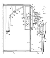
Unten werden die Abbildungen 1, 2 und 3 gleichzeitig besprochen. Es wird bemerkt, daß die Abbildungen alles nur schematisch und von der gesamten Einrichtung lediglich die zum guten Verständnis wesentlichen Teile darstellen. Die dargestellte Einrichtung ist zum schrittweisen Betrieb von der Bedienungseite aus bestimmt, welche in den Abbildungen 1 und 3 die linke Seite der Abbildungen und in Abbildung 2 die untere Seite ist.Figures 1, 2 and 3 are discussed below at the same time. It should be noted that the illustrations represent everything only schematically and of the entire device only the parts essential for a good understanding. The device shown is intended for step-by-step operation from the operating side, which is the left side of the figures in Figures 1 and 3 and the lower side in Figure 2.
Der Rahmen der gesamten Einrichtung ist mit 1 bezeichnet und umfaßt unter anderen zu beiden Querseiten an der Oberseite angebrachte solide waagerechte Balken 2. Auf diesen Balken sind schematisch dargestellte Schienen oder Führungen 3 befestigt, die zur Führung eines Wagens 4 dienen, der mittels schematisch dargestellter Räder 5 auf dem Rahmen in Querrichtung auf den Schienen oder Führungen 3 hin und her bewegt werden kann. Auf dem Wagen sind zwei Stützrollen drehbar gelagert, deren Abstand voneinander auf nicht dargestellte Weise einstellbar ist. Die Stützrollen 6 befinden sich in einer senkrechten Ebene, senkrecht zur Längsrichtung der Einrichtung. Sie sind auf ihrem Umfang mit festen, die Reibung steigernden Verkleidungen 7 versehen, beispielsweise mit massiven Gummireifen. In die Einklemmung der Rollen wird ein zu bearbeitender Pfahl 8 gelegt. Dank der Einstellbarkeit des Abstands zwischen dem Stützrollenpaar kann bei Pfählen 8 mit unterschiedlichen Durchmessern die Höhe so eingestellt werden, daß die Achse des Pfahls 8 immer annähernd in derselben waagerechten Ebene liegen wird. Obwohl dies nicht dargestellt worden ist, ist es für den Fachmann selbstverständlich, daß zur guten Stützung des Pfahls wenigstens eine entsprechende Stützrollenkombination in der Nähe des anderen Endes der Einrichtung befindlich ist. Auch dieses Stützrollenpaar ist auf entsprechende Weise auf dem Wagen 4 befestigt. Für die Bearbeitung des Anspitzens des Pfahls 8 und des etwaigen Abkan tens soll der Pfahl 8 fest auf die Stützrollen 6 gepreßt werden, damit die Schneidkräfte, die von den weiter unten zu besprechenden Schneidvorrichtungen ausgeübt werden, den Pfahl weder fortschleudern, noch ins Schwingen versetzen können. Dazu ist auf dem Rahmen 1 eine Niederhaltevorrichtung 9 angebracht worden, und zwar jeweils eine Niederhaltevorrichtung 9 zur Zusammenarbeit mit einem Stützrollenpaar 6. Die Niederhaltevorrichtung 9 besteht aus einem straff gespannten Riemen, der um drehbar in Entfernung zueinander gelagerte Scheiben 11 gelegt worden ist. Die Lagerung der Scheiben 11 erfolgt auf bekannte Weise an einem Arm 12, der gelenkig bei 13 um eine waagerechte Achse parallel zur Längsrichtung der Einrichtung über eine Stütze 14 auf dem Rahmen 1 befestigt ist. Die Gelenkachse 13 befindet sich ungefähr in Höhe der Oberseite eines zu berabeitenden Pfahls 8. In der gezeichneten Position in Abb. 1, der Ruheposition, ruht der Arm 12 an einem auf nicht dargestellte Weise einstellbaren Anschlag 15. Aus der dargestellten Position kann die Niederhaltevorrichtung 9 somit scharnierend nach oben drehen, wie durch Pfeil 18 angegeben und in Abb. 3 dargestellt ist. Mittels einer starken Blattfeder 16 wird die Niederhaltevorrichtung 9 über eine die Reibung verringernde Verkleidung 17, beispielsweise aus einem PTFE hergestellt, im Ruhezustand auf den Anschlag 15 herabgedrückt und im Betrieb (Abb. 3) auf einen zu bearbeitenden Pfahl 8. Schematisch ist in den Abbildungen 1 und 2 die Fräse 19 angegeben, die zum Anspitzen des Pfahls 8 bestimmt ist. Die Achse der Fräse 19 liegt annähernd in derselben Ebene, in der sich die Achse des Pfahls 8 bei der Querverstellung des Wagens 4 bewegt. Unten wird die Fräse 19 näher erläutert werden.The frame of the entire device is denoted by 1 and includes, among other things, solid horizontal bars 2 attached to both transverse sides at the top. Schematically illustrated rails or guides 3 are fastened to these bars, which serve to guide a carriage 4 by means of schematically represented
Die Stützrollen 6 jeden Paars werden synchron mit derselben Drehrichtung mittels beispeilsweise eines Kettengetriebes 21 von einer einstellbaren Spannrolle 23 aus angetrieben, welche Spannrolle 23 ihrerseits über ein Kettengetriebe 22 durch einen Motor 24 angetrieben wird. Letzterer ist mit der Spannrolle 23 auf dem Wagen 4 befestigt. Alle Stützrollenpaare der Einrichtung werden mit nicht näher angegebene bekannten Mitteln ständig synchron miteinander angetrieben. Dazu können die Antriebe zwischen den einzelnen Stützrollenpaaren mittels beispielsweise axial ein- und ausziehbarer Kardanwellen 231 miteinander gekoppelt sein, doch können die Antriebsmotoren auch elektrisch synchronisiert sein.The
Den Querantrieb des Wagens 4 besorgt ein schematisch dargestellter hydraulischer oder pneumatischer Kraftzylinder 25, der gelenkig an einem Stuhl 26 befestigt ist, der seinerseits auf einem der unteren Balken des Rahmens 1 angeordnet ist. Die ausgehende Stange 27 des Zylinders 25 ist gelenkig mit einem Hebel 28, 29 gekoppelt, der zwischen seinen Enden gelenkig an einem Stuhl 31 gelagert ist, der seinerseits ebenfalls am Rahmen 1 befestigt ist. Die gelenkige Lagerung des Hebels 28, 29 umfaßt eine Achse 30, die parallel zur Längsrichtung des Rahmens von einem Ende zum anderen Ende verläuft und nahe den Enden im Stuhl 31 gelagert ist. Bei ausreichend großer Torsionssteifigkeit der Achse 30 wird, ausgehend von einem einzigen Kraftzylinder 25, der Wagen 4 nahe seinen beiden Enden in genau gleicher Weise angetrieben werden. An seinem freien Ende ist der Hebel 29 wieder gelenkig über eine Stange 32 mit einer Kupplung 33 des Wagens 4 verbunden. Bedienung des Kraftzylinders 25, der in den Abbildungen doppeltwirkend ist, jedoch auch einfachwirkend sein kann, in welchem letzteren Falle er mit einer Rückstellfeder versehen sein soll, sorgt für die Querverstellung des Wagens 4. Dieser ist in Abb. 1 in der Extremlage an der Bedienungsseite der gesamten Einrichtung dargestellt, wo bearbeitete Pfähle 8 entfernt und neue eingelegt werden. Von der in Abb. 1 dargestellten Beschickungs- und Entladeposition des Wagens 4 wird dieser infolge der Verlängerung des Kraftzylinders 25, 27 in den Abbildungen nach rechts verstellt, wobei sich der zu bearbeitende Pfahl 8 zunächst der Niederhaltevorrichtung 9 und danach der Fräse 19 nähert. Um die Zyklusdauer möglichst zu beschränken, ist es erwünscht, die Querverstellung anfangs schnell stattfinden zu lassen, bis zu dem Zeitpunkt, an dem die Niederhaltevorrichtung 9 den Pfahl 8 festgreift. Weil kurz danach die Fräsbearbeitung beginnt, soll auf dieser Strecke der Querverstellung die Vorschubgeschwindigkeit beträchtlich abnehmen, um die Fräsbearbeitung mit einer annähernd konstanten niedrigen Vor schubgeschwindigkeit durchzuführen. Dazu kann bei kontinuierlicher Speisung des Zylinders 25 mit Druckmittel, das Gestänge in der dargestellten Weise ausgeführt sein. In Abb. 1 ist der Winkel zwischen dem Hebel 29 und der Pleuelstange 32 spitz und durchläuft den 90°-Bereich, so daß bei konstanter Verlängerung des Zylinders 25 eine hohe Vorschubgeschwindigkeit auftritt. Kommt der Wagen in den Bearbeitungsbereich L (Abb. 2), dann hat die Vorschubgeschwindigkeit beträchtlich abgenommen, da der Winkel zwischen dem Hebelarm 29 und der Stange 32 immer weiter gestreckt wird. Dadurch nimmt nicht nur die Vorschubgeschwindigkeit beträchtlich ab, wie dies erwünscht ist, sondern nimmt ebenfalls die von dem Zylinder ausgeübte Vorschubkraft beachtlich zu. Weil, wie in den Abbildungen 1 und 2 dargestellt, sich die Fräse 19 ungefähr in derselben Ebene befindet, in der der Pfahl 8 in Querrichtung verstellt wird, ist die Bearbeitungsstrecke L nur kurz im Vergleich zu der gesamten Querverstellung S, wie in Abb. 3 wiedergegeben. Es wird deutlich sein, daß beide Endlagen genauestens bestimmt sein müssen, um in der Beschickungs- und Entladestellung nach Abb. 1 den Wagen rechtzeitig abzubremsen und am Ende der Bearbeitungsstrecke L nach der vollständigen Bearbeitung der Spitze 9 nicht noch mehr Material unnötigerweise vom Pfahl abzufräsen. Dazu können nicht-dargestellte Mittel wie beispielsweise Grenzschalter angewandt werden, die die Betätigung des Kraftzylinders steuern. Zur Sicherung können ausserdem nicht-dargestellte einigermaßen federnde Notstoppanschläge vorgesehen sein. Ein nicht-dargestellter (hydraulischer) Dämpfer kann die Vorschubbewegung auf der Frässtrecke weiter stabilisieren.The transverse drive of the carriage 4 is provided by a schematically illustrated hydraulic or
Wie aus dem Vorstehenden hervorgeht, wird der Pfahl 8 auf seinen Stützrollen 6 durch den Antrieb 21-24 rotiert, und dieser nimmt die freigelagerten Niederhalterollen 11 und den Riemen 10 bei ihrer Rotation mit. Zur gedanklichen Vorstellung kann gesetzt werden, daß bei üblichen Fichtenholzpfählen mit etwa 10 cm Durchmesser die Frässtrecke in etwa 2 Sekunden zurückgelegt wird und der Pfahl 8 dabei etwa 10 Umdrehungen macht.As can be seen from the foregoing, the pile 8 is rotated on its
Weiter wird klar sein, daß die Rotation des Pfahls 8 im Beschickungs- und Entladezustand nach Abb. 1 aufgehört haben muß, um der Bedienungsperson die Beschickung und Entladung zu erleichtern und sicherer zu machen. Mittels nicht-dargestellter jedoch an sich bekannter Mittel, beispielsweise bedienbarer Schalter beim Passieren des Wagens 4 oder mittels einer Steuerung von außen, wird der Motor 24 nur in der Bearbeitungsstrecke L und kurz davor sowie kurz danach betätigt werden. Wenn der Wagen 4 in der Beschickungs- und Entladestellung stillsteht, soll der Antrieb 24 in jedem Fall gestoppt sein.It will also be clear that the rotation of the pile 8 in the loading and unloading state according to FIG. 1 must have stopped in order to make loading and unloading easier and safer for the operator. By means not shown but known per se, for example operated switch when passing the car 4 or by means of a control from the outside, the
Für den Fachmann ist es selbstverständlich, daß an Stelle einer Bedienung mit dem beschriebenen Kraftzylinder 25 viele andere Antriebe möglich sind, beispielsweise mit Gewindespindeln und ähnlichen. Deren Bewegungszyklus soll jedoch im wesentlichen wie oben beschrieben verlaufen.It is self-evident for the person skilled in the art that instead of an operation with the described
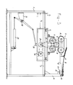
In Abbildung 3 ist, wie sich schon aus dem vorigen ergibt, der Pfahl 8 an das Ende der Frässtrecke L geraten und mit einer Spitze versehen. Die Niederhaltevorrichtung 9 ist dabei um einen kleinen Winkel nach oben um Gelenkachse 13 gekippt und wird dabei mit zunehmender Kraft mittels der Blattfeder 16 an den Pfahl gedrückt. Dadurch ist der Arm 12 vom Anschlag 15 freigekommen, wie dies durch Pfeil 125 angegeben worden ist.In Figure 3, as can be seen from the previous one, the pile 8 has come to the end of the milling section L and has a tip. The hold-down
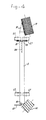
In Abbildung 2 sind weitere Einzelheiten, sofern von Bedeutung, schematisch wiedergegeben. Der Rahmen 1 trägt an seiner Oberseite einen Längsträger 51 an der Rückseite und einen Längsträger 52 an der Bedienungsseite. Darauf einstellbar befestigt ist ein Querrahmen 47, 48, 478 zur Stützung der Fräse 19 und ihres Antriebs. Dieser Fräsrahmen ist etwas erhöht, so daß der Wagen 4 darunter frei hin- und herbeweglich ist. Er ist jedoch zugleich von geringer Höhe, so daß die Fräse 19 in der gewünschten Höhe liegt, und der Pfahl 8 frei auf dem Fräsrahmen hin und her bewegt werden kann. Zur Längeneinstellung des zu fräsenden Pfahls ist der Fräsrahmen in Längsrichtung einstellbar auf dem Hauptrahmen 1. Dazu sind in den waagerechten Balken 51 und 52 Schlitze 50 angebracht worden, in denen mit schematisch wiedergegebenen, bequem zu bedienenden Befestigungsmitteln 49 der Fräsrahmen befestigt werden kann. Die Fräse 19 ist zusammen mit ihrem Antriebsmotor 40 und ihrem Getriebe 41 auf bekannte, nicht-dargestellte Weise solide drehbar auf einem Drehtisch 44 gelagert. Der Drehtisch 44 ist schwenkbar um Achse 42 und kann in unterschiedlichen Winkelpositionen gegenüber dem Fräsrahmen mittels eines Schlitzes 43 und eines dadurch hindurchsteckenden Befestigungsmittels 431, beispielsweise Bolzen und Klemmutter, festgesetzt werden. Mittels dieser Einstellbarkeit wird die Rotationsachse der Fräse gegenüber der Achse des Pfahls eingestellt, so daß der Scheitelwinkel der zu bearbeitenden Spitze des Pfahls eingestellt werden kann. Die Drehplatte 44 wird ihrerseits von einer Platte 45 gestützt, die mittels Schlitzen 46 und zugehörigen Befestigungsmitteln einstellbar auf dem Fräsrahmen 47, 48, 478 befestigt ist. Letztere Einstellmöglichkeit 46 dient vor allem dazu, die Fräse optimal einstellen zu können, wenn Pfähle mit großen Durchmesserunterschied angespitzt werden müssen. Zugleich kann damit ein unterschiedlicher Fräsdurchmesser ausgeglichen werden, der beispielsweise eine Folge des Nachschleifens sein kann.Further details, if relevant, are shown schematically in Figure 2. The
Weiter sind in Abb. 2 die Längsbalken 53 und 54 des Wagens 4 klar zu erkennen, auf denen die Stützrollen 6 mit ihrer Stützung befestigt sind.Furthermore, in Fig. 2 the
Obwohl nicht dargestellt, kann es unter Umständen erwünscht sein, die oben beschriebene schrittweise funktionierende Einrichtung so auszuführen, daß sowohl die Seite 52 wie die Seite 51 beide Beschickungs- und Entladeseiten sind, oder aber daß die eine Seite ausschließlich Beschickungs- und die andere Seite ausschließlich Entladeseite ist. In dem Falle wird die Fräse 19 über der Verstellungsbene der Pfähle 8 liegen müssen, damit die Pfähle darunter hindurch verstellt und inzwischen angespitzt und abgekantet werden können. Die Bedienungseinrichtung des Wagens 4 wird dem selbstverständlich angepaßt werden müssen, während die Stützung 14 der Niederhaltevorrichtung 9 in der Weise geändert werden muß, daß sie an dieser Seite der Einrichtung das Beschicken und Entladen nicht hemmt. Die dabei erforderliche Position der Fräse 19 wird unten an Hand der Abbildungen 4, 5 und 6 näher erläutert.Although not shown, it may be desirable to implement the step-by-step mechanism described above so that both
Abb. 4 zeigt schematisch eine Oberansicht der an Hand der Abbildungen 1, 2 und 3 beschriebenen Einrichtung. Der Pfahl 8 stützt sich auf die beschriebene Weise auf den Stützrollenpaaren 6, 7. Jedes Paar ist in der Nähe eines zu fräsenden Endes des Pfahls angeordnet. In dieser Abbildung ist die schon beschriebene Fräse 19 zur Herstellung der Spitze 9 dargestellt. Außerdem ist die Fräse 191 zum Anbringen der Abkantung 82 am anderen Ende des Pfahls dargestellt. Diese Fräse 191 ist so angeordnet, daß eine Abkantung 82 mit dem üblichen Winkel von etwa 45°-60° zur Achse des Pfahls mit nur geringer Materialabspanung hergestellt werden kann. Um alle Pfähle genau gleich lang zu machen, ist es vorteilhaft, einen Anschlagsbalken 60 anzuwenden, der sich parallel zur Querverstellungsrichtung des Wagens 4 erstreckt und an den die Pfähle beim Beschicken angelegt werden und an dem sie während ihrer vollständigen Vorschubbewegung liegen bleiben. Es ist ja immerhin möglich, daß durch die relativ großen Kräfte , die von der Fräse 19 beim in kurzer Zeit Anspitzen des Pfahls ausgeübt werden, auf diesen eine axiale Kraft ausgeübt wird, die den Pfahl in eine Richtung von der Fräse 19 weg zu verschieben versuchen würde. Dadurch wird das abzukantende Ende des Pfahls immer sicher an dem Anschlagsbalken 60 ruhen.Fig. 4 shows schematically a top view of the device described with reference to Figures 1, 2 and 3. The pile 8 is supported in the manner described on the pairs of
Es wird klar sein, daß die Fräse 191 auch durch eine Spitzfräse ersetzt werden könnte, um Pfähle mit zwei Spitzen herzustellen, oder andersherum, könnte die Fräse 19 durch eine Abkantfräse 119 ausgewechselt werden oder aber in eine Position versetzt werden, um ebenfalls abzukanten.It will be appreciated that the
Es ist mit der beschriebenen Einrichtung ebenfalls möglich, aus langen Pfählen zwei kurze Pfähle zu machen. In dem Falle wird zu beiden Pfahlenden eine Spitze gefräst werden und wird in oder nahe der Mitte eine dritte Fräseinheit auf dem Rahmen 1 angebracht werden müssen, die zum zweiseitigen Abkanten und Durchsägen geeignet ist. In Ausnahmefällen könnte auch dort angespitzt werden. Zur Stützung der zwei erhaltenen kurzen Pfähle sollen, wie dem Fachmann klar sein wird, entsprechende Stützrollenpaare 6, 7 und Niederhaltevorrichtungen 9 zu beiden Seiten der dritten Fräs-Säge-Einheit auf dem Wagen angebracht werden. Es wird auch klar sein, daß in einer Anzahl der oben beschriebenen besonderen Anwendungen der Einrichtung der Anschlagsbalken 60 entfernt sein muß.It is also possible with the described device to make two short piles from long piles. In this case, a tip will be milled to both pole ends and a third milling unit, which is suitable for double-sided folding and sawing, will have to be attached to the
In den Abbildungen 5 und 6 ist schematisch die oben beschriebene Einrichtung dahingehend geändert worden, daß sie zum kontinuierlichen Anspitzen und/oder Abkanten von Pfählen geeignet ist. Es wird eine Querförderanlage für kontinuierlichen Betrieb der Anspitz- und/oder Abkanteinrichtung von Pfählen dargestellt. Alles was nachfolgend nicht besonders umschrieben worden ist, stimmt mit der obigen Beschreibung der schrittweise funktionierenden Einrichtung überein. Die Funktion ist grundsätzlich dieselbe: Die Pfähle werden in Querrichtung zugeführt und unter der Fräse (den Fräsen) hindurchtransportiert, damit eine Spitze und/oder eine Abkantung angebracht wird. Auch hier sind die Abbildungen stark schematisiert. Obwohl lediglich die Fräse zum Anspitzen angegeben worden ist, wird klar sein, daß eine ähnliche Fräse am anderen Pfahlende zum Abkanten angewandt werden kann, oder in Ausnahmefällen zum zweiseitigen Anspitzen.In Figures 5 and 6, the device described above has been modified schematically so that it is suitable for the continuous tipping and / or folding of piles. A cross conveyor system for continuous operation of the tipping and / or folding device of piles is shown. Everything that has not been specifically described below corresponds to the above description of the step-by-step device. The function is basically the same: the piles are fed in the transverse direction and transported under the milling machine (the milling machines) so that a point and / or a bevel is attached. Here, too, the illustrations are highly schematic. Although only the cutter for sharpening has been specified, it will be clear that a similar cutter at the other end of the pile can be used for folding, or in exceptional cases for double-sided sharpening.
Die Querförderanlage besteht nun aus wenigstens zwei endlosen gespannten Förderketten, die in der senkrechten Ebene parallel zueinander und senkrecht zur Achse der Pfähle mittels Umleitungsrädern 67, 68 auf dem Rahmen auf bekannte Weise gelagert sind. Von den Förderketten ist nur die Kette 65, 66 an der Seite der Spitzfräse 19 dargestellt worden. Der obere Teil 65 wird dabei auf voller Länge von einer Kufe 69 gestützt, die durch geeignete Stützen 70 fest auf dem Rahmen gestützt ist. Parallel dazu ist die Niederhaltekette 61, 62 um Umleitungsrollen 63 und 64 gespannt. Dazwischen wird die Serie kontinuierlich zu bearbeitender Pfähle 84-89 eingeklemmt und bewegt. In Abb. 5c ist schematisch das Bewegungssystem angegeben, auf das unten näher zurückgekommen wird. Im Blick auf eine bequeme Erreichbarkeit zum Auswechseln und/oder Schleifen der Fräse 19 ist diese im wesentlichen oberhalb der Pahlbahn angeordnet. Einfachheitshalber sind in den Zeichnungen die Lagerung und der Antrieb ausgelassen, stimmen sie doch grundsätzlich mit den zu den Abbildungen 1-3 Beschriebenen überein. Die Rotationsachse 20 der Fräse 19 steht in jedem Fall in einem Winkel α nach Abb. 5b zur Achse der Pfähle, damit eine Spitze 81 an den Pfählen gefräst wird. Die Fräse kann erforderlichenfalls höher gegenüber der Pfahllänge eingestellt werden, um die mit Punktlinie angegebene stumpfe Spitze 83 zu bekommen, die vorteilhaft sein kann, wenn die Pfähle in steinigen Boden oder dergleichen eingeschlagen werden müssen. Mit der Einstellung des Winkels α wird der Scheitelwinkel der Pfahlspitze eingestellt. In Abb. 5a ist zu sehen, daß die Achse 20 der Fräse ebenfalls einen Winkel β zur Achse der Pfähle haben kann, um die wirksame Frässtrecke L auf mehrere Pfähle gleichzeitig zu verteilen, so daß die auf den Pfahl ausgeübten Fräskräfte kleiner, die Fräsbelastung konstanter und die Schnittrichtung mehr mit dem Faserverlauf mitgehen werden. Die in den Abbildungen dargestellte Frässtrecke stimmt mit L überein. Die Pfähle 84, 85 und 86 werden somit in dieser Momentaufnahme der Fräsbearbeitung unterzogen und sollen deswegen ausreichend fest zwischen Förderband und Niederhalteband eingeklemmt sein. Zuallererst sind die Bänder an ihrer tragenden Seite mit feinen scharfen Zacken oder ähnlichen versehen, wie schematisch mit 651 angegeben, um ohne nennenswerte Beschädigung der Pfahloberfläche die Pfähle trotzdem rutschfest festzugreifen. Wie schon vorher zu den Abbildungen 1, 2 und 3 erwähnt, drehen sich die Pfähle um ihre eigene Achse während ihrer Vorschubbwegung unter der Fräse hindurch. Dazu wird nach Abb. 5c der obere Teil 65 des Förderbands mit einer linearen Geschwindigkeit |Vtr| angetrieben, während der untere Teil 62 des Niederhaltebands in entgegengesetzter Richtung mit einer geringeren Geschwindigkeit |Vn| bewegt. Die Umfangsgeschwindigkeit, mit der der Pfahl rotiert, stimmt annäherungsweise mit |Vtr| überein, jedoch mit der Vorschubrichtung entgegengesetzter Richtung. Die Vorschubgeschwindigkeit |Va| ist gering und beträgt:
Es wird dem Fachmann klar sein, daß eine Anzahl der beweglichen Teile im Blick auf eine zuverlässige und langlebige Funktion mit bekannten Mitteln und auf bekannte Weise gegen Späne geschützt und staubdicht abgeschirmt sind, welche Mittel jedoch im Blick auf die Einfachheit und Deutlichkeit der Zeichnungen nicht dargestellt worden sind. Weiter ist es im Zusammenhang mit der relativ hohen Produktionsgeschwindigkeit erwünscht, daß die Fräsen kleine Zacken mit viel zwischengelegenem Spanraum haben, und daß die Zacken auf einer Schraubenlinie mit geringer Gewindesteigung angebracht sind, damit keine Bahnen in der verarbeiteten Pfahloberfläche zurückbleiben und die Fräsen nicht leicht verstopfen können. Kleine Späne lösen sich außerdem leichter und sind meistens sofort für Verarbeitung zu Spanplatten geeignet. Im Blick auf die leichte Herstellung und das bequeme Schleifen der Fräsen ist es vorteilhaft, zylindrische Fräsen anzuwenden, wie dargestellt. Fräsen mit langen Schneiden, die Hobelspäne bilden, sind weniger geeignet, mit wegen ihrer größeren Empfindlichkeit gegen z.B. Knorren im Holz. Dem Fachmann wird weiter deutlich sein, daß eine korrekte rechtwinklige Zufuhr der Pfähle zu der Förderkette erforderlich ist, dazu sind aber verschiedene bekannte Einrichtungen zu verwenden, die deswegen nicht beschrieben und dargestellt zu werden brauchen. Auf der schon beschriebenen Weise entsprechende Weise kann auch die kontinuierliche Einrichtung dafür ausgelegt werden, aus längeren Pfählen zwei kürzere zu machen.It will be clear to a person skilled in the art that a number of the moving parts are protected against chips and are shielded from dust in order to ensure reliable and long-lasting function with known means and in a known manner, but these means are not shown in view of the simplicity and clarity of the drawings have been. Furthermore, in connection with the relatively high production speed, it is desirable that the milling cutters have small tines with a lot of chip space between them, and that the tines are mounted on a screw line with a small thread pitch, so that there are no tracks in remain on the processed pile surface and cannot easily clog the cutters. Small chips also come off more easily and are usually immediately suitable for processing into chipboard. In view of the ease of manufacture and convenient grinding of the cutters, it is advantageous to use cylindrical cutters as shown. Milling with long cutting edges that form wood shavings are less suitable, because of their greater sensitivity to knots in wood, for example. It will also be clear to the person skilled in the art that correct, right-angled feeding of the piles to the conveyor chain is required, but various known devices must be used for this purpose, which therefore need not be described and illustrated. In the manner already described, the continuous device can also be designed to make longer piles into two shorter ones.
Claims (13)
- einen länglichen Rahmen (1, 2, 51, 52),
- wenigstens eine darauf angeordnete Querförderanlage (4; 62, 65), die dafür ausgelegt ist, einem oder mehreren in Längsrichtung darauf mitgenommenen Pfählen (8) sowohl eine Vorschubverstellung in Querrichtung gegenüber dem länglichen Rahmen wie auch eine Rotation um seine/ihre Achse zu geben,
- wenigstens eine auf dem Rahmen befestigte rotierend angetriebene Fräse (19), deren Rotationsachse (20) in einem Winkel zur Richtung der Achse eines Pfahls steht, wenn dieser durch die Querförderanlage in den Arbeitsbereich (L) der Fräse gebracht worden ist, welcher Winkel eine Komponente sowohl gegenüber der waagerechten (α) wie gegenüber der senkrechten Ebene (β) haben kann, wobei der wirksame Bereich der Schnittfläche der Fräse höhenverstellbar gegenüber der Ebene ist, in der die Querverstellung des Pfahls stattfindet, und wobei die Position der Fräse (der Fräsen) in Längsrichtung des Rahmens zur Anpassung an die Pfahllänge einstellbar ist.1. Device for tipping and / or chamfering round piles, characterized in that the device comprises:
- an elongated frame (1, 2, 51, 52),
- At least one transverse conveyor system (4; 62, 65) arranged thereon, which is designed to give one or more piles (8) carried along in the longitudinal direction both a feed adjustment in the transverse direction with respect to the elongated frame and a rotation about its axis ,
- At least one rotatably driven milling cutter (19) fastened to the frame, the axis of rotation (20) of which is at an angle to the direction of the axis of a pile, if this has been brought into the working area (L) of the milling cutter by the transverse conveyor system, which angle one Component can have against both the horizontal (α) and the vertical plane (β), the effective area of the cutting surface of the milling cutter being height-adjustable compared to the plane in which the transverse adjustment of the pile takes place, and the position of the milling cutter (of the milling ) is adjustable in the longitudinal direction of the frame to adapt to the pile length.
dies alles in der Weise, daß ein auf die Stützrollen gelegter Pfahl mitrotiert und rotierend durch den Quervorschub des Wagens (4) gegen die Einlaufkante der Unterseite des umspannenden Riemens (19) stößt und sich dieser daraufhin federnd nach oben scharnierend dreht, wobei der rotierende Pfahl den frei rotierenden Riemen (10) mitrotieren läßt, wodurch eine feste Einschließung und rotierender Antrieb des Pfahls während des gesamten Fräsvorgangs auf der Frässtrecke (L) gewährleistet sind.8. Device according to claims 6 or 7, characterized in that a stationary hold-down device (9) is mounted on the frame vertically above each pair of support rollers, which only covers the area (L) of the transverse movement on which the pile is milled, which Hold-down device each comprises two freely rotating discs (11) with the axis of rotation parallel to the pile axis, and both of which are located in the vertical plane by the associated support roller pair, and wherein the axes of the hold-down discs are at least at a distance from one another which coincides with the milling path and above the two pulleys of each pair a belt (10), for example a V-belt, is taut, each hold-down device being articulated about a horizontal axis (13) parallel to the axis of the pile at a distance from the milling section (L) and approximately at the height of the pile is attached to the frame and by a resilient hold-down device (16) on one adjustable stop (15) is pressed down, the distance in the idle state between the top of the support rollers (6, 7) and the bottom of the hold-down discs (11) is slightly less than the thickness of the pile,
all in such a way that a pile placed on the support rollers also rotates and rotates through the transverse feed of the carriage (4) against the leading edge of the underside of the encircling belt (19) and then rotates resiliently upward, the rotating pile allows the freely rotating belt (10) to rotate, thereby creating a firm enclosure and rotating drive of the pile is guaranteed during the entire milling process on the milling section (L).

Applications Claiming Priority (2)
| Application Number | Priority Date | Filing Date | Title |
|---|---|---|---|
| NL8503288A NL8503288A (en) | 1985-11-27 | 1985-11-27 | DEVICE FOR POINTING AND / OR CROWNING OF POSTS. |
| NL8503288 | 1985-11-27 |
Publications (1)
| Publication Number | Publication Date |
|---|---|
| EP0226237A1 true EP0226237A1 (en) | 1987-06-24 |
Family
ID=19846936
Family Applications (1)
| Application Number | Title | Priority Date | Filing Date |
|---|---|---|---|
| EP86201984A Withdrawn EP0226237A1 (en) | 1985-11-27 | 1986-11-12 | Pole-pointing and/or cutting apparatus |
Country Status (3)
| Country | Link |
|---|---|
| EP (1) | EP0226237A1 (en) |
| DE (1) | DE8631264U1 (en) |
| NL (1) | NL8503288A (en) |
Cited By (2)
| Publication number | Priority date | Publication date | Assignee | Title |
|---|---|---|---|---|
| AT465U1 (en) * | 1994-11-22 | 1995-11-27 | Fuerlinger August | DETACHING MACHINE |
| IT201800007912A1 (en) * | 2018-08-07 | 2020-02-07 | Scm Group Spa | Machine tool with improved system for handling panels or the like. |
Families Citing this family (1)
| Publication number | Priority date | Publication date | Assignee | Title |
|---|---|---|---|---|
| NL1029944C2 (en) * | 2005-09-13 | 2007-03-15 | Edward De Jong | Wooden tenon forming machine, has centering pin and cutting device oriented at acute angle to each other |
Citations (19)
| Publication number | Priority date | Publication date | Assignee | Title |
|---|---|---|---|---|
| NL123244C (en) * | 1959-03-25 | 1900-01-01 | ||
| US1621963A (en) * | 1923-06-04 | 1927-03-22 | Nat Pole & Treating Company | Pole-puncturing machine |
| US1744875A (en) * | 1927-12-28 | 1930-01-28 | William W Edwards | Guard and workholder for planers |
| US1955437A (en) * | 1932-03-12 | 1934-04-17 | Harry E Oeser | Pole planing machine |
| US1993064A (en) * | 1934-04-02 | 1935-03-05 | Blanc Eugene Le | Machine for grinding shuttle points |
| FR815816A (en) * | 1934-03-22 | 1937-07-23 | Assistant | |
| GB550902A (en) * | 1941-12-01 | 1943-01-29 | Tubes Ltd | A machine for trimming the ends of cylindrical metal tubes or bars |
| US2766785A (en) * | 1955-04-25 | 1956-10-16 | Armand A Joyal | Wood working jig |
| US2840127A (en) * | 1954-06-05 | 1958-06-24 | Abitibi Power & Paper Co | Apparatus for making wood shavings |
| US3451449A (en) * | 1967-02-06 | 1969-06-24 | Bouma Post Yards | Post pointing and capping apparatus |
| CA911861A (en) * | 1972-03-20 | 1972-10-10 | Domtar Limited | Post domer |
| DE2121943A1 (en) * | 1971-05-04 | 1972-11-23 | H. Brunotte KG, 3200 Hildesheim | Device for sharpening nail tips |
| FR2261849A1 (en) * | 1967-10-27 | 1975-09-19 | Hardtle Wilhelm | Round log debarking machine - has belts in V-pattern supporting and rotating log during machining |
| US4048761A (en) * | 1976-07-09 | 1977-09-20 | Champion International Corporation | Paper stick pointing apparatus |
| DE2822771A1 (en) * | 1978-05-24 | 1979-12-06 | Pauli Josef Bauschlosserei | Multiple end chamfered dowel cutting machine - has guide battens, revolving belt cutting discs on shaft, and saw shaft |
| US4363342A (en) * | 1977-11-04 | 1982-12-14 | Bruks Mekaniska Ab | Log milling apparatus |
| DE3134823A1 (en) * | 1981-09-03 | 1983-03-17 | G.A. Pfleiderer GmbH & Co KG, 8430 Neumarkt | Method and device for bevelling the ends of round wood (round timber) |
| WO1984002105A1 (en) * | 1982-11-30 | 1984-06-07 | John Flessum | Machine for removing thickened root portions on timber |
| FR2541618A1 (en) * | 1983-02-25 | 1984-08-31 | Kombak Maschinenfabrik Gmbh Co | METHOD AND DEVICE FOR MILLING THE BIRTH OF ROOTS ON LOGS |
-
1985
- 1985-11-27 NL NL8503288A patent/NL8503288A/en not_active Application Discontinuation
-
1986
- 1986-11-12 EP EP86201984A patent/EP0226237A1/en not_active Withdrawn
- 1986-11-26 DE DE19868631264 patent/DE8631264U1/de not_active Expired
Patent Citations (19)
| Publication number | Priority date | Publication date | Assignee | Title |
|---|---|---|---|---|
| US1621963A (en) * | 1923-06-04 | 1927-03-22 | Nat Pole & Treating Company | Pole-puncturing machine |
| US1744875A (en) * | 1927-12-28 | 1930-01-28 | William W Edwards | Guard and workholder for planers |
| US1955437A (en) * | 1932-03-12 | 1934-04-17 | Harry E Oeser | Pole planing machine |
| FR815816A (en) * | 1934-03-22 | 1937-07-23 | Assistant | |
| US1993064A (en) * | 1934-04-02 | 1935-03-05 | Blanc Eugene Le | Machine for grinding shuttle points |
| GB550902A (en) * | 1941-12-01 | 1943-01-29 | Tubes Ltd | A machine for trimming the ends of cylindrical metal tubes or bars |
| US2840127A (en) * | 1954-06-05 | 1958-06-24 | Abitibi Power & Paper Co | Apparatus for making wood shavings |
| US2766785A (en) * | 1955-04-25 | 1956-10-16 | Armand A Joyal | Wood working jig |
| NL123244C (en) * | 1959-03-25 | 1900-01-01 | ||
| US3451449A (en) * | 1967-02-06 | 1969-06-24 | Bouma Post Yards | Post pointing and capping apparatus |
| FR2261849A1 (en) * | 1967-10-27 | 1975-09-19 | Hardtle Wilhelm | Round log debarking machine - has belts in V-pattern supporting and rotating log during machining |
| DE2121943A1 (en) * | 1971-05-04 | 1972-11-23 | H. Brunotte KG, 3200 Hildesheim | Device for sharpening nail tips |
| CA911861A (en) * | 1972-03-20 | 1972-10-10 | Domtar Limited | Post domer |
| US4048761A (en) * | 1976-07-09 | 1977-09-20 | Champion International Corporation | Paper stick pointing apparatus |
| US4363342A (en) * | 1977-11-04 | 1982-12-14 | Bruks Mekaniska Ab | Log milling apparatus |
| DE2822771A1 (en) * | 1978-05-24 | 1979-12-06 | Pauli Josef Bauschlosserei | Multiple end chamfered dowel cutting machine - has guide battens, revolving belt cutting discs on shaft, and saw shaft |
| DE3134823A1 (en) * | 1981-09-03 | 1983-03-17 | G.A. Pfleiderer GmbH & Co KG, 8430 Neumarkt | Method and device for bevelling the ends of round wood (round timber) |
| WO1984002105A1 (en) * | 1982-11-30 | 1984-06-07 | John Flessum | Machine for removing thickened root portions on timber |
| FR2541618A1 (en) * | 1983-02-25 | 1984-08-31 | Kombak Maschinenfabrik Gmbh Co | METHOD AND DEVICE FOR MILLING THE BIRTH OF ROOTS ON LOGS |
Cited By (3)
| Publication number | Priority date | Publication date | Assignee | Title |
|---|---|---|---|---|
| AT465U1 (en) * | 1994-11-22 | 1995-11-27 | Fuerlinger August | DETACHING MACHINE |
| IT201800007912A1 (en) * | 2018-08-07 | 2020-02-07 | Scm Group Spa | Machine tool with improved system for handling panels or the like. |
| EP3608051A1 (en) * | 2018-08-07 | 2020-02-12 | SCM Group S.p.A. | Machine tool with an improved system for moving panels or the like |
Also Published As
| Publication number | Publication date |
|---|---|
| NL8503288A (en) | 1987-06-16 |
| DE8631264U1 (en) | 1987-04-09 |
Similar Documents
| Publication | Publication Date | Title |
|---|---|---|
| EP0443122B1 (en) | Saw with vertical strap saw-blade | |
| DE3724321B4 (en) | Two cutting band saw | |
| DE2548771C3 (en) | Feed and clamping device for a cutting machine | |
| DE2507449A1 (en) | MACHINE SHEARS | |
| CH667609A5 (en) | MACHINE SCISSORS. | |
| DE3927275C2 (en) | ||
| EP1810769A1 (en) | Panel working machine with a saw unit | |
| DE2905786A1 (en) | VENEER SHEARING MACHINE | |
| AT390025B (en) | DEVICE FOR PRODUCING PRISMATIC OR PYRAMID-BASED BARS | |
| CH692027A5 (en) | Method and apparatus for handling a bandsaw while manufacturing or repair operations. | |
| DE4341864C2 (en) | Device for removing welding beads from plastic pallets and cutting devices used thereby | |
| EP0226237A1 (en) | Pole-pointing and/or cutting apparatus | |
| DE19547193C2 (en) | Method and device for cutting a tree trunk | |
| DE4326890A1 (en) | Apparatus for grinding the edges of plate- or panel-shaped workpieces | |
| EP0400530A2 (en) | Device for cutting pieces into lengths | |
| DE2752648A1 (en) | Circular cutter attached to cross slide - produces tapered lead=in edge on moving strip material | |
| DE2542647A1 (en) | METHOD AND DEVICE FOR CUTTING VARIOUS MATERIALS, IN PARTICULAR PIECES OF WOOD | |
| DE459501C (en) | Machine for grinding the teeth of saw blades | |
| DE10013970A1 (en) | Rod-form wood element processing device has holding unit which can rotate wood element about its longitudinal axis | |
| DE3100644A1 (en) | Apparatus for splitting logs | |
| DE532070C (en) | Machine for preparing flat printing plates | |
| DE1703806B2 (en) | MACHINE FOR SEPARATING WOODEN BODIES, ESPECIALLY HALF-LOGS, INTO INDIVIDUAL GUTTER-SHAPED ELEMENTS | |
| DE3517146A1 (en) | Machine for making dovetail joints | |
| DE2517792C3 (en) | Device for making toothpicks of essentially triangular cross-section from wooden blocks | |
| DE2632425A1 (en) | MACHINE FOR OPENING ENVELOPES |
Legal Events
| Date | Code | Title | Description |
|---|---|---|---|
| PUAI | Public reference made under article 153(3) epc to a published international application that has entered the european phase |
Free format text: ORIGINAL CODE: 0009012 |
|
| AK | Designated contracting states |
Kind code of ref document: A1 Designated state(s): AT BE CH DE ES FR GB GR IT LI LU NL SE |
|
| 17P | Request for examination filed |
Effective date: 19871214 |
|
| 17Q | First examination report despatched |
Effective date: 19890202 |
|
| STAA | Information on the status of an ep patent application or granted ep patent |
Free format text: STATUS: THE APPLICATION IS DEEMED TO BE WITHDRAWN |
|
| 18D | Application deemed to be withdrawn |
Effective date: 19900523 |