EP0225316A1 - Method and apparatus for winding wedge-shaped segments for an electrical coil of an electrical transformer - Google Patents
Method and apparatus for winding wedge-shaped segments for an electrical coil of an electrical transformer Download PDFInfo
- Publication number
- EP0225316A1 EP0225316A1 EP87200039A EP87200039A EP0225316A1 EP 0225316 A1 EP0225316 A1 EP 0225316A1 EP 87200039 A EP87200039 A EP 87200039A EP 87200039 A EP87200039 A EP 87200039A EP 0225316 A1 EP0225316 A1 EP 0225316A1
- Authority
- EP
- European Patent Office
- Prior art keywords
- winding
- wire
- wedge
- coil
- core
- Prior art date
- Legal status (The legal status is an assumption and is not a legal conclusion. Google has not performed a legal analysis and makes no representation as to the accuracy of the status listed.)
- Withdrawn
Links
Images


Classifications
-
- H—ELECTRICITY
- H01—ELECTRIC ELEMENTS
- H01F—MAGNETS; INDUCTANCES; TRANSFORMERS; SELECTION OF MATERIALS FOR THEIR MAGNETIC PROPERTIES
- H01F41/00—Apparatus or processes specially adapted for manufacturing or assembling magnets, inductances or transformers; Apparatus or processes specially adapted for manufacturing materials characterised by their magnetic properties
- H01F41/02—Apparatus or processes specially adapted for manufacturing or assembling magnets, inductances or transformers; Apparatus or processes specially adapted for manufacturing materials characterised by their magnetic properties for manufacturing cores, coils, or magnets
- H01F41/0206—Manufacturing of magnetic cores by mechanical means
- H01F41/0213—Manufacturing of magnetic circuits made from strip(s) or ribbon(s)
- H01F41/022—Manufacturing of magnetic circuits made from strip(s) or ribbon(s) by winding the strips or ribbons around a coil
-
- H—ELECTRICITY
- H01—ELECTRIC ELEMENTS
- H01F—MAGNETS; INDUCTANCES; TRANSFORMERS; SELECTION OF MATERIALS FOR THEIR MAGNETIC PROPERTIES
- H01F27/00—Details of transformers or inductances, in general
- H01F27/28—Coils; Windings; Conductive connections
- H01F27/32—Insulating of coils, windings, or parts thereof
- H01F27/322—Insulating of coils, windings, or parts thereof the insulation forming channels for circulation of the fluid
-
- H—ELECTRICITY
- H01—ELECTRIC ELEMENTS
- H01F—MAGNETS; INDUCTANCES; TRANSFORMERS; SELECTION OF MATERIALS FOR THEIR MAGNETIC PROPERTIES
- H01F30/00—Fixed transformers not covered by group H01F19/00
- H01F30/06—Fixed transformers not covered by group H01F19/00 characterised by the structure
- H01F30/16—Toroidal transformers
-
- H—ELECTRICITY
- H01—ELECTRIC ELEMENTS
- H01F—MAGNETS; INDUCTANCES; TRANSFORMERS; SELECTION OF MATERIALS FOR THEIR MAGNETIC PROPERTIES
- H01F41/00—Apparatus or processes specially adapted for manufacturing or assembling magnets, inductances or transformers; Apparatus or processes specially adapted for manufacturing materials characterised by their magnetic properties
- H01F41/02—Apparatus or processes specially adapted for manufacturing or assembling magnets, inductances or transformers; Apparatus or processes specially adapted for manufacturing materials characterised by their magnetic properties for manufacturing cores, coils, or magnets
- H01F41/04—Apparatus or processes specially adapted for manufacturing or assembling magnets, inductances or transformers; Apparatus or processes specially adapted for manufacturing materials characterised by their magnetic properties for manufacturing cores, coils, or magnets for manufacturing coils
- H01F41/06—Coil winding
- H01F41/077—Deforming the cross section or shape of the winding material while winding
-
- H—ELECTRICITY
- H01—ELECTRIC ELEMENTS
- H01F—MAGNETS; INDUCTANCES; TRANSFORMERS; SELECTION OF MATERIALS FOR THEIR MAGNETIC PROPERTIES
- H01F41/00—Apparatus or processes specially adapted for manufacturing or assembling magnets, inductances or transformers; Apparatus or processes specially adapted for manufacturing materials characterised by their magnetic properties
- H01F41/02—Apparatus or processes specially adapted for manufacturing or assembling magnets, inductances or transformers; Apparatus or processes specially adapted for manufacturing materials characterised by their magnetic properties for manufacturing cores, coils, or magnets
- H01F41/04—Apparatus or processes specially adapted for manufacturing or assembling magnets, inductances or transformers; Apparatus or processes specially adapted for manufacturing materials characterised by their magnetic properties for manufacturing cores, coils, or magnets for manufacturing coils
- H01F41/06—Coil winding
- H01F41/082—Devices for guiding or positioning the winding material on the former
-
- H—ELECTRICITY
- H01—ELECTRIC ELEMENTS
- H01F—MAGNETS; INDUCTANCES; TRANSFORMERS; SELECTION OF MATERIALS FOR THEIR MAGNETIC PROPERTIES
- H01F41/00—Apparatus or processes specially adapted for manufacturing or assembling magnets, inductances or transformers; Apparatus or processes specially adapted for manufacturing materials characterised by their magnetic properties
- H01F41/02—Apparatus or processes specially adapted for manufacturing or assembling magnets, inductances or transformers; Apparatus or processes specially adapted for manufacturing materials characterised by their magnetic properties for manufacturing cores, coils, or magnets
- H01F41/04—Apparatus or processes specially adapted for manufacturing or assembling magnets, inductances or transformers; Apparatus or processes specially adapted for manufacturing materials characterised by their magnetic properties for manufacturing cores, coils, or magnets for manufacturing coils
- H01F41/06—Coil winding
- H01F41/098—Mandrels; Formers
Definitions
- the invention concerns a method and apparatus for winding wedge-shaped coil-segments of an electrical transformer particularly in respect of toroidal transformers in which the coil is wound in substantial part from a continuous conductor.
- an electrical toroidal transformer having a continuously- wound, annular or toroidal core and continuous toroidal low voltage and high voltage windings would provide a transformer of nearly optimum operating efficiency.
- the continuously wound annular or toroidal core would minimize the effective magnetic path length and the parasitic core losses.
- the continuous toroidal electrical windings would optimize the use of an annular or toroidal core by providing the smallest effective electrical coil path length.
- Previously known transformer constructions have not, however, accomplished all of these objectives.
- At least one winding is formed from a pre-insulated continuous wire by:
- each wedge-shaped segment is wound and formed from a continuous wire or conductor.
- the present invention also provides apparatus for forming said winding having a number of wedge-shaped segments on a mandrel, which apparatus is characterised in that a pair of winding forms are spaced apart on the mandrel so as to define a wedge-shaped space therebetween, and in that it further comprises means for winding said wire around said winding mandrel, guide means for feeding said wire onto said winding mandrel between said winding forms as the wire is being wound around said winding mandrel, and bonding means for bonding said wire as wound into said wedge-shaped space between said winding forms, whereby said wire maintains said wedge-shape of said wedge-shaped space after removal from said winding forms.
- FIGS 1 through 41 of the drawings depict various preferred and alternate embodiments of the present invention for purposes of illustration only.
- One skilled in the art will readily recognize from the following discussion that still other alternate embodiments of the structures and methods illustrated herein may be employed without departing from the principles of the invention described herein.
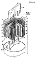
- Figures 1 through 3 illustrate a preferred toroidal electrical transformer 10 including a continuously wound, toroidal or annular core 20 disposed within a core insulation tube 30.
- a low voltage coil or winding 40 surrounds the core insulation tube 30 and is encased by a high/low insulation barrier 50, which. is in turn surrounded by a high voltage coil or winding 60.
- the high voltage winding 60 is preferably made up of two sections 61 and 62, each including a plurality of winding bundles or segments continuously wound from a common wire and connected by loops of said common wire, e.g., twenty 2-1 ⁇ 2% voltage segments in each of said sections. At least the segments of the high voltage winding 60 near the ends of the sections 61 and 62 are preferably separated by inserts 70, around which said loops extend, for purposes of minimizing impulse stresses resulting from any non-linear voltage distribution to which the high voltage winding may be subjected, such as those encountered during high voltage impulses caused, for example, by lightning. Such inserts 70 may in some cases be required between all high voltage winding segments as shown in the drawings, or more than one insert may be required between each segment.
- the inserts 70 are preferably composed of a synthetic material, such as "MYLAR” or “KAPTON” for example, and are retained in place by thermo-formed cuffs 71 which extend circumferentially under the high voltage winding segments as shown in Figure 2.
- the preferred low voltage winding 40 is also made up of two sections 41 and 42, corresponding to the high voltage winding sections 61 and 62.
- Such preferred low voltage coil sections 41 and 42 may each include either a singular winding conductor, bifilar or multifilar parallel conductors in an interleaved configuration, one of such parallel conductors for each voltage winding, as is explained in detail below.
- the high voltage winding sections 61 and 62 and the low voltage winding sections 41 and 42 each extend circumferentially through an arc of approximately 165 degrees on each side of the transformer 10.
- the core insulation tube 30 and the high/low insulation barrier 50 are each formed in two-section pairs 31, 32 and 51, 52, respectively, with each of the sections extending circumferentially through an arc of approximately 165 degrees on each of the two sides of the preferred transformer 10.
- the low voltage coil 40 is preferably disposed within the high voltage coil 60, and the two coils preferably encompass approximately 165 degrees of the circumferential length of the toroidal or annular core 20.
- continuous as used herein in connection with the high voltage winding or coil 60, and the sections 61 and 62 thereof, includes a preferred configuration wherein the wedge-shaped segments and the connecting loops are wound and formed from a single wire or conductor that is continuous over the length of each of the high voltage coil sections 61 or 62, or in other words, over substantially one-half of the toroidal transformer 10.
- continuous also refers to various alternate configurations of the high voltage coil 60, wherein at least each wedge-shaped segment is wound from such a continuous wire or conductor.
- the term “continuous” includes the above-mentioned preferred singular, bifilar or multifilar arrangements, wherein the conductor is continuous over the length of each of the low voltage coil sections 41 or 42, or over the length of each of the interleaved windings for each section, as is described in detail below in connection with Figure 14.
- the low voltage coil is continuous over substantially one-half of the toroidal transformer 10.
- the term “continuous” also includes any of several alternate low voltage coil structures wherein at a minimum the low voltage conductor, whether singular, multifilar, or otherwise, and whether interleaved or not, is continuous over at least three turns thereof.
- continuous includes such core structures wound from a single or multifilar group of ribbon-like strips of continuous core material as well as a successive, serially-connected group of core material strips, wound-in successively to form increasingly large diametric regions of the core 20.
- statoroidal or “annular” as used herein in connection with the high and low voltage coils 60 and 40, respectively, and in connection with the magnetic core 20, refer to the configuration of a torus generated by the revolutions of any of a number of regular or irregular shapes about an external axis.
- the various preferred and alternative structures and configurations of the high and low voltage windings or coils 60 and 40, respectively, and of the magnetic core 20 are described in detail below.
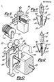
- Figures 4 and 4A represent detail views of the section 31 of a preferred core insulation tube 30. Although the section 31 is shown in Figures 4 and 4A for purposes of illustration, one skilled in the art will appreciate that the section 32 is identical to the section 31.
- the core insulation tube section 31 includes a pair of upper and lower half-sections 33 which are preferably molded from a synthetic material and are identical in configuration but inverted with respect to each other. Thus the four identical half-sections required to form the core insulation tube 30 may all be molded from a single mold.
- the half-sections 33 are preferably molded from a high-strength, glass-filled synthetic material, such as polyester, nylon, or epoxy, for example.
- the half-sections 33 of the core insulation tube 30 each include inner and outer walls 34 and 35, respectively, extending in an axial direction from a base portion 36.
- One or more interlocking protrusions preferably in the form of teeth or tabs 37 protrude axially from the inner wall 34, with a corresponding number of circumferential spaces 38 between adjacent teeth 37.
- the teeth or protrusions 37 and the spaces 38 are oriented such that when the identical upper and lower half-sections 33 are joined together to form the section 31, as shown in Figure 4A, the teeth 37 intermesh to prevent relative circumferential displacement of the inner walls 34 of the upper and lower half-sections 33.
- the teeth 37 have vertical edges oriented along radius lines passing through the center of the transformer 10, thereby providing for a flush, interference-free engagement of the upper and lower teeth 37.
- each inner wall 34 and the teeth 37 is preferably greater than that of the outer leg 35, thereby forming an axial gap 39 around the periphery of the core insulation tube 30 as is illustrated in Figure 4A.
- the purpose of the axial gap 39 will be described in detail below in connection with the core wind-in process illustrated in Figures 29 through 31.
- the teeth 37 are preferably of an axial length or height such that the sections 31 and 32 may be axially collapsed to a height allowing easy insertion into the toroidal opening or arcuate elongated passage formed by the low-voltage coil sections 41 and 42, as will be described below.
- the half-sections 33 may be spread by means of a suitable spreading device such as the wedge-shaped spreader tool 92 shown in Figure 4A, for example.
- a suitable spreading device such as the wedge-shaped spreader tool 92 shown in Figure 4A, for example.
- the spreading of the half-sections 33 after insertion into the low voltage coil section 41 allows the core insulation section 31 to substantially conform to the inside of the low voltage coil section 41 thus providing sufficient space in the arcuate elongated passage for winding in the core 20, as will be described later in this discussion.
- Such spread position may be maintained by providing detents formed on the teeth 37, or by other means known to those skilled in the art.
- FIG. 5 shows the preferred section 51 of the high/low insulation barrier 50, for purposes of illustration.
- section 52 is identical to section 51.
- the section 51 of the high/low insulation barrier 50 includes a pair of upper and lower half-sections 53 and 54, respectively, which like the half-sections 33 of the core insulation tube section 31, may be molded from a suitable reinforced synthetic material.
- the half-sections 53 and 54 must then be compressed axially, thereby allowing for assembly of the high voltage coil segments over the low voltage windings and the core insulation barrier subassembly.
- the particular cross-sectional shapes of the generally toroidal or annular shaped core insulation tube 30 and high/low insulation barrier 50 correspond to the the desired cross-sectional shapes of the toroidal or annular magnetic core 20 and high and low voltage coils 60 and 40, respectively.
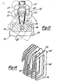
- Figure 6 illustrates a broken-away portion of the high/low insulation barrier 50 including a preferred but not necessary internal wall structure of the present invention.
- the wall structure shown in Figure 6 and the related discussion herein are equally applicable to the core insulation tube 30.
- the high/low insulation barrier 50 in Figure 6 includes a number of ridges 95 molded into the internal side of the outer wall 56.
- the ridges 95 may be inclined, spiral, involute, or the like, and form a plurality of cooling fluid branch channels 96 therebetween.
- the ridges 95 are interrupted short of the base portions 57 and thereby form common header channels 97 at the upper and lower peripheries of the outer wall 56.
- the branch channels 96 and the header channels 97 act as conduits for the convective flow of the cooling liquid.
- the configuration of the ridges 95 being inclined or spiral, etc., imparts a convectively induced circulating motion to the cooling fluid flow throughout the inside of the high/low insulation barrier 50, as illustrated by the flow arrows in Figure 6.
- Such circulating motion promotes both cooling of the components and uniform temperature distribution throughout the transformer.
- the corresponding sections of the above-described components are assembled into two preferred transformer half-portions or sections 11 and 12, each extending circumferentially through an arc of approximately 165 degrees as described above.
- the preferred transformer portions 11 and 12 when combined, thus form a substantial portion of a torus made up of two symmetrical halves with a circumferential space of approximately 15 degrees therebetween on each side.
- One of the primary purposes for the above-described construction is to form an arcuate elongated passage for allowing the core 20 to be continuously wound in place in a toroidal or annular configuration as is illustrated in Figures 1 through 3 and described in detail below.
- the transformer assembly is retained in its proper configuration by means of supporting blocks 80 (see Figure 1), which maintain an equal spacing between the half-portions 11 and 12 on both sides of the transformer 10.
- the transformer assembly is then installed in a suitable containment structure such as the tank or housing 85 shown in Figure 1.
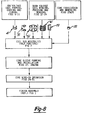
- Figure 8 illustrates, in block diagram form, an overview of the major operations involved in the preferred method of manufacturing the toroidal electrical transformer 10. Although for purposes of illustration, the reference numerals in Figure 8 and in the following discussion relate to the transformer half-portion 11, the structure and production methods of the transformer half-portion 12 are preferably identical to those of the transformer half-portion 11.
- the low voltage coil section 41 is preferably wound from continuous conductor stock with each turn being formed into a wedge shape to provide the toroidal or annular configuration. Preferably, each turn is formed with a generally constant cross-sectional area throughout. The formed coil is then coated with insulation, and the insulation is cured to finish the coil section 41.
- the above low voltage coil producing steps are described in detail below in connection with Figures 9 through 16 of the drawings.
- the low voltage coil 41 is then positioned onto the exterior of the pre-assembled core insulation barrier 31 and encased within the upper and lower halves of the high/low insulation barrier section 51 as is shown schematically in Figure 7.
- the sub-assembly is then ready for addition of the high voltage coil section 61.
- the high voltage coil section 61 is preferably wound from a continuous wire and formed into a number of wedge-shaped bundles or segments. The segments are then compressed, and the individual turns of wire in each segment are bonded together to form a tightly wound continuous coil with a greater number of turns of the wire per unit cross-sectional area of the coil than existed before the segments were compressed. Such increase in the number of turns per unit cross-sectional area of the coil maximizes the use of the volume of the toroidal or annular space and thereby increases the efficiency of the transformer.
- the inserts 70 are located at each end of the high voltage coil section 61 and between adjacent segments with the cuffs 71 extending into the toroidal openings in the segments.
- the high voltage coil section 61 and the inserts 70 are then positioned onto the exterior of the high/low insulation barrier section 51 to complete the operation of forming the half-portion 11 prior to the winding in of the core 20.
- the core material which is of a relatively thin, ribbon-like configuration, is preferably pre-wound into a tight coil and automatically severed at a prescribed length determined by the size of the transformer being produced.
- the coil is then restrained and annealed to relieve its internal stresses, as is illustrated in Figures 25 and 26.
- the resultant structure is a pre-wound, coil-shaped core 20 which is ready for winding into the above-described transformer half-portions 11 and 12.
- the remaining steps in the production process include forming and installing a core sleeve from a blank of core material, if deemed to be necessary for the particular core material being used ( Figures 27 and 28); the winding of the pre-formed, pre-annealed core 20 i---to the arcuate elongated passage through the interdisposed high and low voltage coils 60 and 40, respectively, ( Figures 29 through 31); and the finished assembly steps of installing the supporting blocks, electrically connecting the respective sections of the low voltage coil 40 and the high voltage coil 60, and mounting the assembly in a suitable housing structure (see Figure 1).
- Figures 9 through 13 illustrate a preferred winding and forming apparatus 120 for fabricating the low voltage coil sections 41 and 42, which may be composed of suitable conductor material such as aluminum or copper.
- the preferred aluminum coil may be fabricated from preshaped EC grade conductor stock of the redraw type or from other suitable conductor stock known to those skilled in the art.
- the coil feedstock 121 which may be round, square, or other desirable cross-section, is fed from a reel 122 onto a forming mandrel 123 having a cross-sectional shape corresponding to the desired cross-sectional shape of the toroidal low voltage coil 40.
- the forming mandrel 123 which is secured to a rotating shaft 124, includes a forming die plate 125 and an axially-projecting shoulder portion 126 for receiving the feedstock 121.
- the feedstock 121 is engaged and pressed into the desired cross-sectional . shape by means of a conical pressure roller 127 and a vertically reciprocating cylindrical pressure roller 128, which cooperate with the forming mandrel 123 to forcibly deform the feedstock 121 into the desired shape as the shaft 124 rotates.
- a conical backing roller 129 provides a counteracting force against the opposite side of the forming mandrel 123 to balance the force exerted by the conical pressure roller 127, thereby providing the lateral stability required for the forming operation.
- a guide 131 directs the formed coil onto a storage mandrel 132 that rotates in unison with the forming mandrel 123, thereby producing a continuously wourd coil configuration which is wound around the storage mandrel 132 as the process continues.
- the cylindrical roller 128 is free-floating between the conical pressure roller 127 and the conical backing roller 129 in the preferred embodiment and is supported vertically by a pair of cylindrical back-up rollers 137.
- the cylindrical back-up rollers 137 are rotatably attached to the yoke member 138.
- a pressure piston which may be a pneumatic or hydraulic device, urges the cylindrical back-up rollers 137 against the cylindrical roller 128, which in turn forcibly engages the conductor feedstock 121 during the forming operation.
- the use of the two spaced-apart cylindrical back-up rollers 137 provides clearance for the conical rollers 127 and 129 as the cylindrical roller 128 oscillates in engagement with the forming mandrel 123 and the conductor feedstock 1 21.
- the sides of the cylindrical roller 128 are slightly concave, thereby limiting the contact with the conical rollers to only the rim portion of the cylindrical roller 128 in order to minimize scuffing and wear resulting from differences in the surface speed of the rollers.
- a single cylindrical roller (not shown) may be rotatably supported by a yoke member and may be sized large enough to avoid interference between its axis and the conical rollers 127 .and 129. Such a single cylindrical roller would also have concave sides to minimize scuffing and friction therebetween. In such an arrangement, however,- the cylindrical roller would have to be reciprocable laterally so as to maintain its pressure point between the lines of contact of the conical rollers.
- Figures 11, 12, and 13 illustrate schematically the relationship of the forming components during various stages of rotation cf the forming mandrel 123
- Figure 14 shows a number of wedge-shaped interleaved turns of the formed low voltage coil 40 as discussed in detail below.
- an inner leg 44 of the low voltage coil 40 is being formed.
- the inner leg 44 is wide in the radial direction and thin in the circumferential direction, said directions being relative to the toroidal or electrical transformer 10.
- the cylindrical roller 128 is in following engagement with the edge 130 of the forming die plate 125 of the forming mandrel 123.
- the axial thickness of the forming die plate 125 is large compared to the overall thickness of the forming mandrel 123 thereby forming a thin cavity in which the conductor feedstock 121 is forced.
- the feedstock 121 is forcibly compressed and deformed into a generally quadrilateral space having a high height-to-width aspect ratio, thereby forming the inner leg 44 of the low voltage coil 40.
- the forming mandrel 123 has rotated 180 degrees from the position shown in Figure 11 in order to form an outer leg 43 of the low voltage coil 40.
- the preferred outer leg 43 is generally quadrilateral in cross-section, with a low height-to-width aspect ratio. Accordingly, in Figure 12, the thickness of the forming die plate 125 is thin compared to the overall thickness of the forming mandrel 123, thereby forming a thicker cavity into which the conductor feedstock 121 is forced.
- the cylindrical roller 128 raises and lowers in following engagement with the corners of the forming mandrel 124. Also, the radial excursion of the die forming plate 125 increases to form the wedge-shaped upper portion 45 and, subsequent to forming the inner portion 44, decreases to form the wedge-shaped lower portion 46.
- the preferred low voltage coil 40 two lengths of coil formed as described above are intertwined or interleaved into a generally double-spiral, or double-helix, configuration as is illustrated in Figure 14 to form one of the coil sections 41 or 42.
- Each of such coil lengths in the low voltage coil section 41 is connected in series to a corresponding coil length in the low voltage coil section 42 upon final assembly of the toroidal transformer 10.
- Each of such lengths is designed for.one-fourth of the total low voltage.
- each of the resultant sections 41 and 42 of low voltage coil 40 when connected as described above, comprises two parallel toroidal coil lengths, interleaved in a double-helix configuration, each of said sections 41 and 42 being designed to carry one-half of the total low voltage value of the transformer.
- One end of each of such parallel coil lengths is connected to one of two low voltage transformer terminals, and the opposite end of each coil length is connected together to the common neutral terminal of the transformer. This connection facilitates a low voltage electrical output (or input), with one half of such voltage being above neutral and one-half below neutral for ease of single-phase multivoltage wiring.
- the low voltage coil 40 were to be fabricated in a non-interleaved configuration, with only a single half-voltage coil length in each coil section 41 or 42, and with all of the high voltage coil segments of the entire high voltage coil 60 being connected in series, an application of a half-voltage load (e.g., 120 volts) to one of such low voltage coil sections 41 or 42 would result in an excessively high circuit impedance. This is because one-half of the series-connected high voltage coil 60 would be dimensionally far removed from the low voltage coil section being used.
- a half-voltage load e.g. 120 volts
- a balanced ampere-turn relationship may be obtained by winding the high voltage coil 60 into two full voltage (e.g., 7200 volts per each coil section 61 or 62) and then simply connecting the coil sections 61 and 62 in parallel, thus obtaining good inductive coupling between each high voltage coil section 61 or 62 and its associated non-interleaved low voltage coil section 41 or 42.
- one of the transformer sections 11 or 12 would provide transformation of one-half the output voltage (e.g. 120 volts) one side of neutral, with the other transformer section providing equal transformation on the opposite side of neutral.
- FIGs 15 and 16 illustrate alternative or optional methods of applying insulation to the formed low voltage coil windings either before or after interleaving.
- a tank 140 contains a liquid insulation coating material 142, into which the coils are dipped and passed by means of a conveyer wire 144 with a series of hanger-type clamps 146 for retaining the formed coils. After the formed coils are dipped in the coating material 142, they are conveyed through a drying and curing apparatus 148 for solidifying the insulation.
- An insulation material recovery system, indicated generally by reference numeral 150 may be employed, if desired, to recycle insulation material vapors from the curing apparatus 148 to the tank 140.
- an alternate powdered insulation material is electrostatically applied to the formed coils in an electrostatic spray bath 152. After application of the powdered insulation, the formed coils are cured in a curing oven 154.
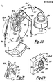
- Figures 17 through 24 illustrate a preferred apparatus and method for winding the high voltage coil 60 with a number of wedge-shaped segments preferably being formed and wound from a continuous wire.
- Figure 17 shows an overall view of a preferred winding apparatus 170, which includes a winding and pressing assembly 172, a rotatable storage mandrel 174, and a wire guide assembly 176 adapted for feeding and guiding a continuous wire 178 into the winding apparatus 170.
- the preferred wire 178 is coated with an insulation material composed of a combination of a fully cured dielectric coating overcoated with a so-called "B" stage semi-cured thermosetting adhesive coating that is dry to the touch.
- the adhesive coating serves to bond the turns together and to enhance the insulating qualities of the insulation,combination.
- Such insulation material as well as other similar materials are known to those skilled in the art.
- the winding and pressing assembly 172 includes an integral winding form 180 and upper and lower portions 182 and 184, respectively of a split winding form 186.
- the integral and split winding forms 180 and 186, respectively, are operatively connected to a winding mandrel 188, which rotates in unison with the rotatable storage mandrel 174.
- the upper and lower portions 182 and 184, respectively, of the split winding form 186 are movable into and out of interlocking engagement with a pair of cavities 190, formed by the winding mandrel 188 and the storage mandrel 174, by means of upper and lower carriers 192 and 194, respectively.
- the upper.and. lower carriers 192 and 194 are operated by a pair of hydraulic or pneumatic cylinders 196, or alternatively by any other suitable mechanical or electrical motion imparting operator known in the art.
- Each of the carriers 192 and 194 includes at least a pair of retaining devices 198 for selectively retaining or releasing the upper and lower portions 182 and 184 of the split winding form 186.
- the preferred retaining devices 198 each include a slidable armature 200 which extends to engage, or retracts to release, one of the retaining apertures 202 on each of the upper and lower form portions 182 and 184.
- the armatures 200 may be actuated by any suitable means such as an electric solenoid device, or by a hydraulic or pneumatic cylinder, for example.
- the preferred upper and lower form portions 182 and 184 also include a pair of locking apertures 204 adapted to receive a pair of locking pins 206 which are extendible from the storage mandrel 174 to retain the upper and lower forms portions 182 and 184 in position in the cavities 190.
- the above-described upper and lower carriers 192 and 194 thus operate to move the upper and lower form portions 182 and 184 into position in the cavities 190 under the force of the cylinders 196, where they are retained by the locking pins 206 and released by the armatures 200, at which point the upper and lower carriers 192 and 194 are retracted as shown in Figure 19.
- the wire guide assembly 176 which may be best seen in Figures 18 through 21, includes vertical feed rollers 212, horizontal feed rollers 214, and a set of guide rollers 216 rotatably mounted on a guide arm 218 which is pivotally secured to a shaft 220.
- the guide rollers 216 automatically oscillate in a lateral direction to direct the wire 178 onto the winding mandrel 188 in a generally uniform pattern, as shown in Figure 20, thereby minimizing the gaps between wire turns and efficiently using the allotted space for each coil segment.
- an insulation piercer 226 located near the feed rollers 212 makes a small cut in the insulation, thereby exposing the bare conductor. The winding then continues until the exposed portion of the wire is indexed in a position where it can be contacted by an electrode 227 after the wire segment 222 is compressed as is described below.
- the electrode 227 is located on the winding mandrel 188 (see Figures 18 and 23), and its purpose is explained below.
- the guide arm 218 and the guide rollers 216 pivot to the position shown in Figure 21 to form the continuous loop portion 221 (see Figure 18), with the above-described exposed portion therein, between each of the coil segments 222 and to allow for the compressing and bonding of the wire in the segments 222.
- Figures 21 through 23 illustrate the preferred apparatus and method for the pressing and bonding of the wire turns of each coil segment 222.
- a pair of rams 230 extend to forcibly decrease the spacing between the.integral winding form 180 and the split winding form 186 from a distance d l , to a distance d 21 as indicated in Figure 21, thereby forcibly compressing the turns of the coil segment 222.
- Such compression of the coil segment 222 further minimizes the space or gaps between the individual turns of wire and thereby maximizes the use of the space around the toroidal transformer 10.
- the integral winding form 180 and the split winding form 186 are preferably hinged, as indicated by reference numeral 187, so as to overcompress the wider outboard leg of the coil segment 222.
- Such hinged arrangement on the winding forms 180 and 186 thereby form sides on the coil winding segment 227 that are parallel both to each other and to a radial center-line through said segment.
- the facing surfaces of the winding forms 180 and 186 may be biplanar with the portions adjacent the outer leg of the coil segment 222 being parallel, thus eliminating the need for the hinges 187 while accomplishing nearly the same result.
- the exposed portion of the wire 178 is engaged by the electrode 227 located on the winding mandrel 188, as is shown in Figure 23.
- Another electrode 229 makes contact with the previously pierced and exposed portion of the wire 178 in the loop portion 221 on the other side of the coil segment 222.
- the winding apparatus 170 then briefly applies a high frequency voltage through the coil segment 222 which quickly heats the periphery of the wire 178 to a temperature of approximately 175°C and causes the thermo-setting adhesive insulation to bond to itself.
- the interior of the wire acts as a heat sink after the voltage is removed.
- the coil segment 222 cools quickly and as a result is wound, compressed and bonded into its final wedge-shaped configuration.
- a high current (D.C. or low frequency A.C.) may be imposed across the coil segment 222, causing an essentially uniform temperature elevation of conductor which in turn causes the surface adhesive coating to flow and bond.
- D.C. or low frequency A.C. may be imposed across the coil segment 222, causing an essentially uniform temperature elevation of conductor which in turn causes the surface adhesive coating to flow and bond.
- the upper and lower carriers 192 and 194 then engage the upper and lower form portions 182 and 184, the locking pins 206 retract, and the armatures 200 extend, as shown in Figure 22, thereby allowing the form portions 182 and 184 to be moved away from the winding mandrel 188.
- the rams 230 extend even further to push the winding form 180 and the coil segment 222 onto the storage mandrel 174.
- the winding form 180 is retracted and the winding of the coil segments from the continuous wire 178 continues as described above until the required number of segments have been formed to make up a complete high voltage coil section 61 or 62, at which time the continuous wire 178 is automatically severed.
- the previously pierced portions of the loop portions 221 are covered with pieces of insulation, if necessary, upon final assembly.
- Figures 25 and 26 illustrate the fabrication and annealing of the core 20, which may be performed independently of the above-described operations.
- the ribbon-shaped stock core material 260 is fed into a core forming apparatus 262, including tension rollers 263 which tightly wind the core material 260 onto a spindle 266, thereby forming a core coil 264, preferably in the size and shape of the finally wound-in core 20 in Figure 1.
- a stack gauge or sensing mechanism 268 causes the winding mechanism to stop and a cutting blade (not shown) to automatically sever the core material 260.
- the core coil 264 is then secured by a steel bonding strap or by spot welding the finished end to the remainder of the coil to maintain its shape and annealed in an annealing oven 270, as shown schematically in Figure 26, to relieve the internal stresses resulting from the winding operation.
- the core winding step may not be necessary.
- the amorphous steel may be wound in place directly into the core insulation tube 30 and annealed in place while a magnetic field is simultaneously being applied by the energized windings, thereby obtaining the optimum magnetic performance due to the core being annealed to its operating position.
- the annealing temperature of amorphous steel is relatively low (approximately 350°C), the insulation on the electrical coils would have to be selected so that it would be capable of withstanding such temperatures for a short time.
- the major components are each fabricated as described above and then assembled into two transformer sections 11 and 12 (see Figure 1), which are joined by means of a core sleeve 280 as is illustrated in Figures 27 and 2Q,
- the use of a core sleeve 280 will generally be required for magnetic cores fabricated from the typically thin amorphous metals, but may not be required for the thicker conventional silicon steel core material (typically 9 mils to 12 mils in thickness) as described below.
- the core sleeve 280 is formed from a strip of core material with one or more protrusions or tabs 282 cut or lanced and bent outwardly from one end thereof.
- the core sleeve 280 may be slightly thicker than that used for winding the core 20 in order to provide added stability during the wind-in process.
- the core sleeve 280 is inserted into the arcuate elongated passage or tunnel in the core insulation tube 30, as shown in Figure 27.
- the ends 284 and 286 are then fixed to each other, with the tabs 282 left in their outwardly-protruding positions, preferably by resistance spot welding as shown in Figure 28.
- the end 286 preferably overlaps the end 284, as shown in Figure 28, so as to form a backward- facing step 292 relative to the direction of rotation of the core sleeve 280 during core wind-in, as indicated by direction arrow 288.
- the provision of the backward- facing step 292 helps to minimize the friction and hang-up between the core sleeve 280 and the core insulation tube sections 31 and 32.
- the core sleeve 280 acts as a bushing or bearing which is freely rotatable about the inner walls of the core insulation tube sections 31 and 32.
- the use of a core sleeve 280 is preferred, at least for amorphous metal core materials, in order to allow the core material to be seated against the tabs 282, and to minimize the possibility of the core material snagging or becoming hung-up on the core insulation tube 30, during the core wind-in operation described below.
- the core sleeve 280 helps to keep the transformer sections axially aligned prior to and during the wind-in operation.
- a suitable carrier (not shown) may also by used when transporting the core-less sub-assembly to be sure that the sections 11 and 12 are maintained in their proper relative positions.
- a pair of transformer section handling clamp-type structures such as those indicated by reference numeral 290 in Figure 27, may also be used for ease in handling the sub-assembly both before, during and after installation of the core sleeve 280.
- a core sleeve 280 may not be necessary for cores fabricated from the thicker conventional silicon steel.
- a tang 281 is formed on the initial end of the core material.
- the tang 281 is adapted to be received in a slot 283 formed in the core material at a distance from the initial end substantially equal to the circumference of the inner wall of the core insulation tube 30.
- the tang 281 is secured in the slot 283 to form an integral core "sleeve", and the wind-in process continues essentially as described below.
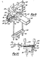
- FIGS. 29 through 31 illustrate the preferred apparatus and method for winding the previously annealed core material 264 into the window or tunnel of the core insulation tube 30.
- a preferred wind-in apparatus 310 generally includes a core material support assembly 312 having a rotating table 314 for rotating the core material 264 during wind-in, a support roller or pulley 315 for supporting the core material 264, a coil support fixture 316 for aligning and supporting the transformer sections 11 and 12, a driven endless drive belt 318 (with a disconnectable joint 320) for supporting and winding in the core material 264, and a belt-tensioning mechanism 322 for automatically maintaining proper tension on the endless drive belt 318 during the wind-in operation.
- the belt-tensioning mechanism 322 may comprise a pneumatic or hydraulic cylinder, for example, with an idler roller or sheave on the outer end of its piston rod for engaging the endless drive belt 318 as shown in Figure 29.
- the pre-assembled coreless transformer sections 11 and 12., with the core sleeve 280 in place, are positioned on the preferred wind-in apparatus 310 with their axis oriented horizontally. Such horizontal axis orientation is preferred so that the endless drive belt 318 may support the weight of the core 20 as it is being wound, thereby aiding in the maintaining of tension on the endless drive belt 318 and in the centering of the core 20 with the transformer sections 11 and 12.
- the weight of the transformer sections 11 and 12 is preferably supported by the coil support fixture 316.
- Various automatic controls known to those skilled in the art are also provided for the various functions described herein.
- the.transformer sections 11 and 12 each extend circumferentially through an arc preferably of approximately 165 degrees, thereby forming a circumferential gap of approximately 15 degrees on each side of the completed toroidal transformer 10.
- the transformer sections 11 and 12, with the core sleeve 280 in place are positioned on the coil support fixture 316, they may be rotated slightly such that the upper gap 324 forms an angle of approximately 25 degrees and the lower gap 326 forms an angle of approximately 5 degrees, thereby allowing sufficient clearance to feed the core material 264 through the upper gap 324 and wind it in place within the core insulation tube 30, thereby forming the annular magnetic core 20.
- the end of the core material 264 is inserted through the upper gap 324 and restrained by the tabs 282 of the core sleeve 280 (see Figures 27 and 28).
- the core material 264 is pre-wound and pre-annealed into a configuration substantially identical to that of the finished core 20. Accordingly, the core material 264 is fed into and wound in place within the core insulation tube 30 from the inside, or inner diameter, of the pre-wound, pre-annealed core coil.
- the finished preferred core 20 is a continuous, tightly wound, substantially stress-free structure, with virtually no air gaps, thereby maximizing the magnetic flux flow of the core 20 and the efficiency of the toroidal electrical transformer 10.
- the endless belt 318 is fed through the upper gap 324 such that it partially surrounds and engages both the core sleeve 280 and the end portion of the core material 264 as is shown in Figure 30.
- the endless drive belt 318 may then be reconnected at the joint 320, and the belt-tensioning mechanism 322 may be activated, thereby tensioning the endless drive belt 318 and preparing the apparatus for the wind-in operation.
- the rotating table 314 beings to rotate at a speed that is automatically synchronized with the movement of the endless drive belt 318, which drivingly feeds and winds the core material 264 through the upper gap 324 and around the core sleeve 280.
- a pair of spring loaded conical rollers 330 are preferably provided on opposite sides of the upper gap 324 and apply a light force on the edges of the core material 264 to keep the layers properly aligned during winding.
- the conical rollers 330 may be driven, if desired, in order to assist the endless drive belt 318 in winding the core material 264.
- a conical shape for such rollers is preferred for purposes of matching their surface speed along the line of contact with the core material 264 with the increasing speed of the core material 264 as the core is rotated during winding.
- the belt-tensioning mechanism 322 automatically adjusts to allow for the increased core diameter and to maintain the proper level of belt tension. The process continues until the core 20 is complete, at which time the endless belt 318 leaves the core insulation tube 30 through the gap 39 between the outer wall portions thereof, as shown in Figure 31.
- the provision of the gap 39 thus allows the core insulation tube 30 to be completely filled with the core material 264 without leaving an unusable annular space for the endless drive belt 318 around the periphery of the core 20.
- the gap 39 may be filled with an insulative transformer cooling fluid, thus achieving dielectric insulation sufficient to withstand voltage stresses between the core and the low voltage windings.
- the transformer sections or half-portions 11 and 12 are rotated back to their original positions with equal circumferential gaps of approximately 15 degrees on each side.
- the corresponding ends of both the low voltage coil sections 41 and 42 and the high voltage sections 61 and 62 are connected together or fitted with external connector devices as required for the desired application of the transformer.
- the upper and lower portions of the supporting blocks 80, shown in Figure 1 are inserted into the 15 degree circumference gaps and are secured together by suitable fastening means known to those skilled in the art.
- the assembly is then ready for mounting in a housing or containment structure, such as that indicated by reference numeral 85 in Figure 1, and for evacuating and charging with transformer cooling fluid, which is typically an electrical grade insulation oil.
- the present invention provides for an electrical transformer, which is suitable for either step-down or step-up applications, and which employs continuously wound high and low voltage coils as well-as a continuous magnetic-core, all of which are arranged in a toroidal or annular configuration.
- the toroidal electrical transformer according to the present invention provides for maximum efficiency and optimum use of space, thereby representing a great stride in the advancement of transformer technology.
- the disclosed method and structure for the continuously wound-in core of the present invention allows the greatest use of the efficiency gains to be derived from the use of the thin-gauge amorphous metal core materials rather than the traditional grain-oriented material.
- Figures 32 through 35 illustrate an alternate method and apparatus for forming the low voltage coil sections 41 and 42.
- the conductor feedstock 121 is fed from the reel 122 by means of a pair of tension rollers 410 onto a rotating mandrel 412, driven by a motor 414.
- a cut-off mechanism 416 automatically severs the feedstock 121.
- the length of coiled feedstock is then conveyed to the forming press 420 shown in Figures 33 and 34.
- the coil length is slipped onto a support mandrel 422 and retained by a bearing plate 423.
- the support mandrel 422 is then moved into a position such that each of the turns 424 of the coil length is between a pair of tapered press forms 424.
- An upper press plate 426 is then forcibly urged downward, as viewed in Figure 34, to compress the turns 424 of the coil length into the same wedge-shaped configuration as is discussed above in connection with the preferred low voltage coil forming apparatus.
- the winding apparatus 430 includes a rotatable head 432 which is movable upwardly and downwardly on a support post 434.
- the upper coil length 436 is attached to the rotatable head 432 and is turned as it is moved downwardly to interleave the upper coil length 436 with the lower coil length 438 which is fixed to a stationary base plate 440.
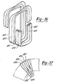
- Figures 36 and 37 illustrate still another alternate low voltage coil structure and a method of forming such a coil.
- the structures and method shown in Figures 36 and 37 are especially well-suited for winding the low voltage coil from pre-insulated conductor because of the limited forming required by such method.
- a pair of parallel bifilar conductors 450 and 452 are wound together.
- Each of the conductors 450 and 452 has a generally rectangular, or possibly square, cross-section and are preferably copper thereby reducing electrical losses and more efficiently using the available space because of the smaller cross-section. It should be noted, however, that it may be desirable for each of the conductors 450 and 452 to be of a different cross-section, one of a square and one of a non-square rectangular cross-section, or each of different rectangular dimensions, for example.
- the bifilar conductors 450 and 452 are wound in a manner so as to lie one inboard of the other in a radial direction, relative to the toroidal transformer, on the inner legs of the low voltage coil. As they are wound, however, the conductors 450 and 452 are turned or rotated 90 degrees in the upper radial portion so as to lie side-by-side in the circumferential direction, relative to the toroidal transformer, on the outer legs. On the lower radial portion, the conductors 450 and 452 are then turned or rotated 90 degrees in the opposite direction, thus returning to their original orientation (one inboard of the other) on the inner legs of the coil.
- Such a construction as shown in Figures 36 and 37, thereby approximates the wedge-shaped configuration of each turn of the above-discussed preferred low voltage coil 40, without the necessity of the substantial forming operations which would tend to damage the pre-insulated conductor.
- a construction may be desirable in applications where such efficient space utilization is not critical. However, through modest forming in conjunction with the turning described above, efficient use of space may be improved.
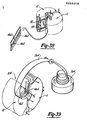
- Figures 38 and 39 illustrate an alternative core wind-in method, employing an alternate core sleeve 460 which includes a plurality of gear teeth 462, preferably stamped or forged therein such that the overall thickness of the core sleeve 460 is not substantially increased over that of its parent material.
- the thickness of core sleeve 460 is preferably greater than that of the core material 264 in order to provide stability during the core wind-in process.
- the alternate core sleeve 460 preferably remains in place in the core insulation tube 30 after completion of the core 20.
- an end of the core material 264 is attached to the core sleeve 460.
- Such attachment may be made in any of a number of ways, such as by spot welding the end of the core material 20 to the outer surface of the core sleeve 460 or by way of lanced tabs thereon similar to the protrusions or tabs 282 shown in Figures 27 and 2e.
- a pinion gear 464 is positioned in the circumferential space or gap 324 between the transformer sections 11 and 12 and drivingly rotated so as to rotate the core sleeve 460 and wind-in the core material 264 in lieu of the endless drive belt 318 of the preferred apparatus shown in Figures.29 and 31 and discussed above.
- Figures 40 and 41 illustrate still another alternate method and apparatus for winding in the core 20, which is perhaps less desirable for use with the thin-gauge amorphous metal core materials than it is for use with the heavier and thicker, grain-ori- ⁇ ented metal materials.
- the inner end of the previously wound and annealed core material 264 is fed through a pair of tensioning rollers 480 and pulled by a drive roller.482 and a spring-loaded back-up roller 483 until a complete loop is formed around the inner walls of the core insulation tube sections 31 and 32.
- a tack weld is made to secure such inner loop to the remainder of the incoming core material 264, and the wind-in process continues until the entire core 20 is formed.
- the inner end of the core material 264 may be secured to a core sleeve 280 as is described above in connection with the preferred wind-in method.
- the core material 264 is supported and rotated on a rotating table 314, similar to that described above, and a pair of conical support rollers 490 are disposed in the gaps between the transformer sections 11 and 12 for vertically supporting the core material 264 during the wind-in process.
Landscapes
- Engineering & Computer Science (AREA)
- Power Engineering (AREA)
- Manufacturing & Machinery (AREA)
- Coils Of Transformers For General Uses (AREA)
- Coils Or Transformers For Communication (AREA)
- Insulating Of Coils (AREA)
- Transformers For Measuring Instruments (AREA)
- Organic Insulating Materials (AREA)
- Liquid Crystal Substances (AREA)
- Apparatus For Making Beverages (AREA)
Abstract
Description
- The invention concerns a method and apparatus for winding wedge-shaped coil-segments of an electrical transformer particularly in respect of toroidal transformers in which the coil is wound in substantial part from a continuous conductor.
- Ideally, an electrical toroidal transformer having a continuously- wound, annular or toroidal core and continuous toroidal low voltage and high voltage windings would provide a transformer of nearly optimum operating efficiency. The continuously wound annular or toroidal core would minimize the effective magnetic path length and the parasitic core losses. Furthermore, the continuous toroidal electrical windings would optimize the use of an annular or toroidal core by providing the smallest effective electrical coil path length. Previously known transformer constructions have not, however, accomplished all of these objectives.
- Various proposals have been made to provide a transformer having a wound, annular core and toroidal windings surrounding the core. For example, the patent to Bastis, et al, U.S. Patent No. 3,430,489, issued September 5, 1967, discloses an air-cooled toroidal transformer in which the core is severed into two segments so that the windings can be positioned onto the core segments before they are joined. A similar technique is shown in the patent to Conner, et al, U.S. Patent No. 3,996,543, issued December 7, 1976. A segmented core is used in Conner, et al, because of the problems associated with winding the primary and secondary windings on a continuous toroidal core using convention winding machines. The present invention is concerned with transformers which are constructed by first forming the windings and assembling them, and thereafter winding core material in the form of a continuous strip, into a toroidal passage defined within and by the windings.
- A process for dipping a pre-formed electrical coil in a liquid insulation bath and curing the insulative coating in an oven is disclosed in a patent issued to Schou, U.S. Patent No. 2,061,388, issued November 17, 1936.
- In the method according to the invention at least one winding is formed from a pre-insulated continuous wire by:
- (a) winding said wire into at least one wedge-shaped segment between a pair of spaced-apart winding forms;
- (b) bonding the turns of wire in said wedge-shaped wegment together;
- (c) removing said bonded wedge-shaped segment; and
- (d) repeating said steps (a), (b) and (c) to wind and bond additional wedge-shaped segments connected to said previously-wound and bonded wedge-shaped segments; whereby a plurality of wound and bonded wedge-shaped segments may be assembled to form said electrical coil for said electrical transformer.
- In the preferred method it is the high voltage coil or winding which is wound into a number of wedge-shaped segments with connecting loops of wire or conductor. Preferably in order to achieve the advantages of the invention, such wedge-shaped segments and connecting loops are wound and formed from a wire or conductor that is continuous over 30 to 50 per cent of the total length of the high voltage coil. At a minimum, each wedge-shaped segment is wound and formed from a continuous wire or conductor.
- The present invention also provides apparatus for forming said winding having a number of wedge-shaped segments on a mandrel, which apparatus is characterised in that a pair of winding forms are spaced apart on the mandrel so as to define a wedge-shaped space therebetween, and in that it further comprises means for winding said wire around said winding mandrel, guide means for feeding said wire onto said winding mandrel between said winding forms as the wire is being wound around said winding mandrel, and bonding means for bonding said wire as wound into said wedge-shaped space between said winding forms, whereby said wire maintains said wedge-shape of said wedge-shaped space after removal from said winding forms.
- Other features and advantages of the invention will become It apparent in the description of the preferred embodiments set forth below.
- Exemplary embodiments of the present invention are illustrated in the accompanying drawings, wherein:
- Figure 1 is a partially cut-away, partially exploded, perspective view of a preferred toroidal electrical transformer according to the preset invention;
- Figure 2 is a partially cut-away top view of the toroidal electrical transformer of Figure 1;
- Figure 3 is a partial cross-sectional view of the toroidal electrical transformer taken along line 3-3 of Figure 2;
- Figure 4 is an exploded perspective view of one section of the preferred core insulation tube of the present invention;
- Figure 4A is a perspective view of an assembled section of the core insulation tube of the present invention and a spreading tool therefor;
- Figure 5 is an exploded perspective view of one section of the preferred high/low insulation barrier of the present invention;
- Figure 6 is a fragmented perspective view of one of the insulation members of the preferred toroidal electrical transformer, illustrating a preferred cooling fluid channel structure;
- Figure 7 is a schematic view illustrating the preferred assembly of the major transformer components prior to installation of the magnetic core;
- Figure 8 is a block diagram, generally illustrating the preferred method of manufacturing a toroidal electrical transformer according to the present invention;
- Figure 9 is an overall view of a preferred low voltage coil forming and winding apparatus used in connection with the present invention;
- Figure 10 is a detail view of the low voltage coil forming portion of the apparatus of Figure 9;
- Figures 11 and 12 are detail views of the low voltage coil forming roller assembly of the apparatus of Figure 9, wherein:
- Figure 11 illustrates the roller position for forming the inner leg of the low voltage coil; and
- Figure 12 illustrates the roller position for forming the outer leg of the low voltage coil;
- Figure 13 is an end view of the low voltage coil forming portion of the apparatus of Figure 9, illustrating various roller and mandrel positions during the coil forming operation;
- Figure 14 is a detail view illustrating a few interleaved turns of two finished low voltage coil lengths;
- Figures 15 and 16 are two variations of the method for applying insulation to the low voltage coil assemblies, wherein:
- Figure 15 illustrates an apparatus for dipping the low voltage coil into a liquid insulation material; and
- Figure 16 illustrates an apparatus for electrostatically applying a powdered insulation material to the low voltage coil;
- Figure 17 is an overall perspective view of an apparatus for winding the high voltage coil and forming a plurality of wedge-shaped segments from a continuous wire;
- Figure 18 is a partially cut-away detail view of the winding and forming portion of the apparatus of Figure 17, with the winding and forming dies in their open position;
- Figure 19 is a partially cut-away view of the winding and forming portion of the apparatus of Figure 17, with the winding and forming dies in their closed position;
- Figure 20 is a top view of the winding and forming portion of the apparatus of Figure 17, illustrating the wire guide assembly therefor;
- Figure 21 through 23 are top views of the winding and forming portion of the apparatus of Figure 17, illustrating the coil segment pressing operation, wherein:
- Figure 21 shows one of such segments after winding and during pressing;
- Figure 22 is similar to Figure 21, but is partially cut-away to show the interlocking structure for one of the split die portions; and
- Figure 23 shows one of such segments in its compressed state during bonding of the wire turns;
- Figure 24 illustrates the insulation piercing structure of the apparatus of Figure 17;
- Figure 25 is a perspective view of an apparatus for pre-winding the core material of the present invention;
- Figure 26 is a schematic representation of the annealing operation of the pre-wound core material of Figure 25;
- Figure 27 is a partially cut-away perspective view of a core sleeve being installed in the core insulation tube of the present invention;
- Figure 28 is a fragmented view showing the ends of the core sleeve of Figure 27 being joined;
- Figure 28A illustrates an arrangement whereby the use of the core sleeve of Figure 28 may be eliminated for a core fabricated from sufficiently thick core material;
- Figure 29 is an overall perspective view of a preferred core wind-in apparatus of the present invention;
- Figure 30 is a schematic view of the major portions of the apparatus of Figure 29;
- Figure 31 is fragmented detail view of the winding belt position at the completion of the core wind-in operation;
- Figure 32 is a side view of an alternate apparatus for winding the low voltage coil of the present invention;
- Figure 33 is a top view of an alternate apparatus for forming the wedge-shaped turns of the low voltage coil;
- Figure 34 is a side view of the apparatus of Figure 33;
- Figure 35 is a side view of an alternate interleaving apparatus for two lengths of low voltage coil;
- Figure 36 is a partially fragmented view of a few representative turns of an alternate low voltage coil structure wound in a generally bifilar arrangement wherein the low voltage coil is wound from a pre-insulated conductor to form approximately wedge-shaped turns of said coil;
- Figure 37 illustrates a few turns of the low voltage coil of Figure 36 as installed on a core insulation tube of the invention;
- Figure 38 illustrates an alternate core sleeve of the present invention;
- Figure 39 illustrates an alternate method for winding in the core material, using the alternate core sleeve of Figure 38;
- Figure 40 is a top view of still another alternate core wind-in apparatus according to the present invention; and
- Figure 41 is a side view of the apparatus of Figure 40.
- Figures 1 through 41 of the drawings depict various preferred and alternate embodiments of the present invention for purposes of illustration only. One skilled in the art will readily recognize from the following discussion that still other alternate embodiments of the structures and methods illustrated herein may be employed without departing from the principles of the invention described herein.
- Figures 1 through 3 illustrate a preferred toroidal electrical transformer 10 including a continuously wound, toroidal or
annular core 20 disposed within acore insulation tube 30. A low voltage coil or winding 40 surrounds thecore insulation tube 30 and is encased by a high/low insulation barrier 50, which. is in turn surrounded by a high voltage coil or winding 60. - The high voltage winding 60 is preferably made up of two
sections sections inserts 70, around which said loops extend, for purposes of minimizing impulse stresses resulting from any non-linear voltage distribution to which the high voltage winding may be subjected, such as those encountered during high voltage impulses caused, for example, by lightning.Such inserts 70 may in some cases be required between all high voltage winding segments as shown in the drawings, or more than one insert may be required between each segment. Theinserts 70 are preferably composed of a synthetic material, such as "MYLAR" or "KAPTON" for example, and are retained in place by thermo-formed cuffs 71 which extend circumferentially under the high voltage winding segments as shown in Figure 2. Similarly, the preferred low voltage winding 40 is also made up of twosections voltage winding sections voltage coil sections voltage winding sections voltage winding sections core insulation tube 30 and the high/low insulation barrier 50 are each formed in two-section pairs 31, 32 and 51, 52, respectively, with each of the sections extending circumferentially through an arc of approximately 165 degrees on each of the two sides of the preferred transformer 10. Thus, thelow voltage coil 40 is preferably disposed within thehigh voltage coil 60, and the two coils preferably encompass approximately 165 degrees of the circumferential length of the toroidal orannular core 20. - The term "continuous" as used herein in connection with the high voltage winding or
coil 60, and thesections voltage coil sections high voltage coil 60, wherein at least each wedge-shaped segment is wound from such a continuous wire or conductor. - With respect to the low voltage winding or
coil 40, and thesections voltage coil sections - The term "continuous", as used with reference to the
magnetic core 20, includes such core structures wound from a single or multifilar group of ribbon-like strips of continuous core material as well as a successive, serially-connected group of core material strips, wound-in successively to form increasingly large diametric regions of thecore 20. - The terms "toroidal" or "annular" as used herein in connection with the high and low voltage coils 60 and 40, respectively, and in connection with the
magnetic core 20, refer to the configuration of a torus generated by the revolutions of any of a number of regular or irregular shapes about an external axis. The various preferred and alternative structures and configurations of the high and low voltage windings or coils 60 and 40, respectively, and of themagnetic core 20 are described in detail below. - Figures 4 and 4A represent detail views of the
section 31 of a preferredcore insulation tube 30. Although thesection 31 is shown in Figures 4 and 4A for purposes of illustration, one skilled in the art will appreciate that thesection 32 is identical to thesection 31. - The core
insulation tube section 31 includes a pair of upper and lower half-sections 33 which are preferably molded from a synthetic material and are identical in configuration but inverted with respect to each other. Thus the four identical half-sections required to form thecore insulation tube 30 may all be molded from a single mold. The half-sections 33 are preferably molded from a high-strength, glass-filled synthetic material, such as polyester, nylon, or epoxy, for example. - The half-
sections 33 of thecore insulation tube 30 each include inner andouter walls base portion 36. One or more interlocking protrusions preferably in the form of teeth ortabs 37 protrude axially from theinner wall 34, with a corresponding number ofcircumferential spaces 38 betweenadjacent teeth 37. The teeth orprotrusions 37 and thespaces 38 are oriented such that when the identical upper and lower half-sections 33 are joined together to form thesection 31, as shown in Figure 4A, theteeth 37 intermesh to prevent relative circumferential displacement of theinner walls 34 of the upper and lower half-sections 33. Theteeth 37 have vertical edges oriented along radius lines passing through the center of the transformer 10, thereby providing for a flush, interference-free engagement of the upper andlower teeth 37. - The axial length or height of each
inner wall 34 and theteeth 37 is preferably greater than that of theouter leg 35, thereby forming anaxial gap 39 around the periphery of thecore insulation tube 30 as is illustrated in Figure 4A. The purpose of theaxial gap 39 will be described in detail below in connection with the core wind-in process illustrated in Figures 29 through 31. Theteeth 37 are preferably of an axial length or height such that thesections voltage coil sections sections 33 may be spread by means of a suitable spreading device such as the wedge-shapedspreader tool 92 shown in Figure 4A, for example. The spreading of the half-sections 33 after insertion into the lowvoltage coil section 41 allows thecore insulation section 31 to substantially conform to the inside of the lowvoltage coil section 41 thus providing sufficient space in the arcuate elongated passage for winding in thecore 20, as will be described later in this discussion. Such spread position may be maintained by providing detents formed on theteeth 37, or by other means known to those skilled in the art. - Figure 5 shows the
preferred section 51 of the high/low insulation barrier 50, for purposes of illustration. One skilled in the art will readily understand thatsection 52 is identical tosection 51. Thesection 51 of the high/low insulation barrier 50 includes a pair of upper and lower half-sections sections 33 of the coreinsulation tube section 31, may be molded from a suitable reinforced synthetic material. A set of inner and outer walls, 55 and 56, respectively, extend axially from each of thebase portions 57 and in the preferred embodiment include opposite-oriented, radially recessedend portions - When the upper and lower half-
sections low voltage coil 41, the respective preferred recessedend portions outer walls 55 and the overlap in a general flush, mating relationship, thereby providing insulation protection to withstand electrical stresses occurring during high impulse voltages associated with thehigh voltage coil 60. The half-sections - The particular cross-sectional shapes of the generally toroidal or annular shaped
core insulation tube 30 and high/low insulation barrier 50 correspond to the the desired cross-sectional shapes of the toroidal or annularmagnetic core 20 and high and low voltage coils 60 and 40, respectively. - Figure 6 illustrates a broken-away portion of the high/
low insulation barrier 50 including a preferred but not necessary internal wall structure of the present invention. The wall structure shown in Figure 6 and the related discussion herein are equally applicable to thecore insulation tube 30. - Transformers of the type disclosed herein frequently employ oil or other fluids, either liquid or gaseous, for cooling their components during operation. Such cooling fluid is typically an electrical grade insulation oil. The high/
low insulation barrier 50 in Figure 6 includes a number ofridges 95 molded into the internal side of theouter wall 56. Theridges 95 may be inclined, spiral, involute, or the like, and form a plurality of coolingfluid branch channels 96 therebetween. Theridges 95 are interrupted short of thebase portions 57 and thereby formcommon header channels 97 at the upper and lower peripheries of theouter wall 56. Thebranch channels 96 and theheader channels 97 act as conduits for the convective flow of the cooling liquid. The configuration of theridges 95, being inclined or spiral, etc., imparts a convectively induced circulating motion to the cooling fluid flow throughout the inside of the high/low insulation barrier 50, as illustrated by the flow arrows in Figure 6. Such circulating motion promotes both cooling of the components and uniform temperature distribution throughout the transformer. - As is shown schematically in Figure 7, the corresponding sections of the above-described components are assembled into two preferred transformer half-portions or
sections preferred transformer portions portions housing 85 shown in Figure 1. Various additional features will become readily apparent from the following description of the methods employed in the manufacture of a toroidal electrical transformer and the components thereof according to the present invention. - Figure 8 illustrates, in block diagram form, an overview of the major operations involved in the preferred method of manufacturing the toroidal electrical transformer 10. Although for purposes of illustration, the reference numerals in Figure 8 and in the following discussion relate to the transformer half-
portion 11, the structure and production methods of the transformer half-portion 12 are preferably identical to those of the transformer half-portion 11. - The low
voltage coil section 41 is preferably wound from continuous conductor stock with each turn being formed into a wedge shape to provide the toroidal or annular configuration. Preferably, each turn is formed with a generally constant cross-sectional area throughout. The formed coil is then coated with insulation, and the insulation is cured to finish thecoil section 41. The above low voltage coil producing steps are described in detail below in connection with Figures 9 through 16 of the drawings. - The
low voltage coil 41 is then positioned onto the exterior of the pre-assembledcore insulation barrier 31 and encased within the upper and lower halves of the high/lowinsulation barrier section 51 as is shown schematically in Figure 7. The sub-assembly is then ready for addition of the highvoltage coil section 61. - The high
voltage coil section 61 is preferably wound from a continuous wire and formed into a number of wedge-shaped bundles or segments. The segments are then compressed, and the individual turns of wire in each segment are bonded together to form a tightly wound continuous coil with a greater number of turns of the wire per unit cross-sectional area of the coil than existed before the segments were compressed. Such increase in the number of turns per unit cross-sectional area of the coil maximizes the use of the volume of the toroidal or annular space and thereby increases the efficiency of the transformer. These operations are described in detail below in connection with Figures 17 through 24. - As is illustrated schematically in Figure 7, the
inserts 70 are located at each end of the highvoltage coil section 61 and between adjacent segments with the cuffs 71 extending into the toroidal openings in the segments. The highvoltage coil section 61 and theinserts 70 are then positioned onto the exterior of the high/lowinsulation barrier section 51 to complete the operation of forming the half-portion 11 prior to the winding in of thecore 20. - The core material, which is of a relatively thin, ribbon-like configuration, is preferably pre-wound into a tight coil and automatically severed at a prescribed length determined by the size of the transformer being produced. The coil is then restrained and annealed to relieve its internal stresses, as is illustrated in Figures 25 and 26. The resultant structure is a pre-wound, coil-shaped
core 20 which is ready for winding into the above-described transformer half-portions - The remaining steps in the production process include forming and installing a core sleeve from a blank of core material, if deemed to be necessary for the particular core material being used (Figures 27 and 28); the winding of the pre-formed, pre-annealed core 20 i---to the arcuate elongated passage through the interdisposed high and low voltage coils 60 and 40, respectively, (Figures 29 through 31); and the finished assembly steps of installing the supporting blocks, electrically connecting the respective sections of the
low voltage coil 40 and thehigh voltage coil 60, and mounting the assembly in a suitable housing structure (see Figure 1). - Figures 9 through 13 illustrate a preferred winding and forming
apparatus 120 for fabricating the lowvoltage coil sections coil feedstock 121, which may be round, square, or other desirable cross-section, is fed from areel 122 onto a formingmandrel 123 having a cross-sectional shape corresponding to the desired cross-sectional shape of the toroidallow voltage coil 40. The formingmandrel 123, which is secured to arotating shaft 124, includes a formingdie plate 125 and an axially-projectingshoulder portion 126 for receiving thefeedstock 121. Thefeedstock 121 is engaged and pressed into the desired cross-sectional . shape by means of aconical pressure roller 127 and a vertically reciprocatingcylindrical pressure roller 128, which cooperate with the formingmandrel 123 to forcibly deform thefeedstock 121 into the desired shape as theshaft 124 rotates. Aconical backing roller 129 provides a counteracting force against the opposite side of the formingmandrel 123 to balance the force exerted by theconical pressure roller 127, thereby providing the lateral stability required for the forming operation. Aguide 131 directs the formed coil onto astorage mandrel 132 that rotates in unison with the formingmandrel 123, thereby producing a continuously wourd coil configuration which is wound around thestorage mandrel 132 as the process continues. - The
cylindrical roller 128 is free-floating between theconical pressure roller 127 and theconical backing roller 129 in the preferred embodiment and is supported vertically by a pair of cylindrical back-uprollers 137. The cylindrical back-uprollers 137 are rotatably attached to theyoke member 138. A pressure piston, which may be a pneumatic or hydraulic device, urges the cylindrical back-uprollers 137 against thecylindrical roller 128, which in turn forcibly engages theconductor feedstock 121 during the forming operation. By supporting thecylindrical roller 128 between theconical rollers conical rollers rollers 137 provides clearance for theconical rollers cylindrical roller 128 oscillates in engagement with the formingmandrel 123 and the conductor feedstock 121. Preferably, the sides of thecylindrical roller 128 are slightly concave, thereby limiting the contact with the conical rollers to only the rim portion of thecylindrical roller 128 in order to minimize scuffing and wear resulting from differences in the surface speed of the rollers. Alternatively, a single cylindrical roller (not shown) may be rotatably supported by a yoke member and may be sized large enough to avoid interference between its axis and theconical rollers 127 .and 129. Such a single cylindrical roller would also have concave sides to minimize scuffing and friction therebetween. In such an arrangement, however,- the cylindrical roller would have to be reciprocable laterally so as to maintain its pressure point between the lines of contact of the conical rollers. - Figures 11, 12, and 13 illustrate schematically the relationship of the forming components during various stages of rotation cf the forming
mandrel 123, and Figure 14 shows a number of wedge-shaped interleaved turns of the formedlow voltage coil 40 as discussed in detail below. In Figure 11, aninner leg 44 of thelow voltage coil 40 is being formed. As may be best seen in Figure 14, theinner leg 44 is wide in the radial direction and thin in the circumferential direction, said directions being relative to the toroidal or electrical transformer 10. Thus, in Figure 11 thecylindrical roller 128 is in following engagement with theedge 130 of the formingdie plate 125 of the formingmandrel 123. Also as is shown in Figure 11, the axial thickness of the formingdie plate 125 is large compared to the overall thickness of the formingmandrel 123 thereby forming a thin cavity in which theconductor feedstock 121 is forced. Thus, thefeedstock 121 is forcibly compressed and deformed into a generally quadrilateral space having a high height-to-width aspect ratio, thereby forming theinner leg 44 of thelow voltage coil 40. - In Figure 12, the forming
mandrel 123 has rotated 180 degrees from the position shown in Figure 11 in order to form anouter leg 43 of thelow voltage coil 40. As may be best seen in Figure 14, the preferredouter leg 43 is generally quadrilateral in cross-section, with a low height-to-width aspect ratio. Accordingly, in Figure 12, the thickness of the formingdie plate 125 is thin compared to the overall thickness of the formingmandrel 123, thereby forming a thicker cavity into which theconductor feedstock 121 is forced. - As the forming
mandrel 123 rotates from its Figure 12 position to its Figure 11 position, as is shown in part in the schematic representation in Figure 13, thecylindrical roller 128 raises and lowers in following engagement with the corners of the formingmandrel 124. Also, the radial excursion of thedie forming plate 125 increases to form the wedge-shapedupper portion 45 and, subsequent to forming theinner portion 44, decreases to form the wedge-shapedlower portion 46. - The winding and forming process described above continues until a predetermined number of low voltage turns have collected on the
storage mandrel 132, at which time theconical pressure roller 127, thecylindrical pressure roller 128, and theconical backing roller 129 are indexed away from the formingmandrel 123 thereby allowing the fabrication of a cross-sectionally unformed terminal portion on the ends of the formed coil. Finally, thefeedstock 121 is automatically severed, the formed coil is removed, and the process is repeated to form another length of low voltage coil. - In forming the preferred
low voltage coil 40, two lengths of coil formed as described above are intertwined or interleaved into a generally double-spiral, or double-helix, configuration as is illustrated in Figure 14 to form one of thecoil sections voltage coil section 41 is connected in series to a corresponding coil length in the lowvoltage coil section 42 upon final assembly of the toroidal transformer 10. Each of such lengths is designed for.one-fourth of the total low voltage. Thus, each of theresultant sections low voltage coil 40, when connected as described above, comprises two parallel toroidal coil lengths, interleaved in a double-helix configuration, each of saidsections voltage coil sections low voltage 120 volt coil section and the fully series-connected winding segments of the entirelength voltage coil 60. - If the
low voltage coil 40 were to be fabricated in a non-interleaved configuration, with only a single half-voltage coil length in eachcoil section high voltage coil 60 being connected in series, an application of a half-voltage load (e.g., 120 volts) to one of such lowvoltage coil sections high voltage coil 60 would be dimensionally far removed from the low voltage coil section being used. If such a non-interleaved low voltage coil configuration is desired, however, a balanced ampere-turn relationship may be obtained by winding thehigh voltage coil 60 into two full voltage (e.g., 7200 volts per eachcoil section 61 or 62) and then simply connecting thecoil sections voltage coil section voltage coil section transformer sections - Although it would be desirable to wind and form the
low voltage coil 40, as described above, from pre-insulated conductor feedstock (e.g., anodized or film-insulated), it may not be possible in some cases to do so by the above-described method without damaging the insulation coating. Therefore, if bare conductor feedstock is used, the formed coil sections should be insulated after forming and winding. Figures 36 and 37, and the corresponding discussion below, illustrates an alternate low voltage coil structure and method of winding that is perhaps better suited for use with pre-insulated conductors. - Figures 15 and 16 illustrate alternative or optional methods of applying insulation to the formed low voltage coil windings either before or after interleaving. In Figure 15, a
tank 140 contains a liquidinsulation coating material 142, into which the coils are dipped and passed by means of aconveyer wire 144 with a series of hanger-type clamps 146 for retaining the formed coils. After the formed coils are dipped in thecoating material 142, they are conveyed through a drying and curingapparatus 148 for solidifying the insulation. An insulation material recovery system, indicated generally byreference numeral 150 may be employed, if desired, to recycle insulation material vapors from thecuring apparatus 148 to thetank 140. - In,Figure 16, an alternate powdered insulation material is electrostatically applied to the formed coils in an
electrostatic spray bath 152. After application of the powdered insulation, the formed coils are cured in a curingoven 154. - Figures 17 through 24 illustrate a preferred apparatus and method for winding the
high voltage coil 60 with a number of wedge-shaped segments preferably being formed and wound from a continuous wire. Figure 17 shows an overall view of a preferred windingapparatus 170, which includes a winding andpressing assembly 172, arotatable storage mandrel 174, and awire guide assembly 176 adapted for feeding and guiding acontinuous wire 178 into the windingapparatus 170. Thepreferred wire 178 is coated with an insulation material composed of a combination of a fully cured dielectric coating overcoated with a so-called "B" stage semi-cured thermosetting adhesive coating that is dry to the touch. The adhesive coating serves to bond the turns together and to enhance the insulating qualities of the insulation,combination. Such insulation material as well as other similar materials are known to those skilled in the art. - As shown in Figures 18 and 19, the winding and
pressing assembly 172 includes an integral windingform 180 and upper andlower portions split winding form 186. The integral and split windingforms mandrel 188, which rotates in unison with therotatable storage mandrel 174. - The upper and
lower portions split winding form 186 are movable into and out of interlocking engagement with a pair ofcavities 190, formed by the windingmandrel 188 and thestorage mandrel 174, by means of upper andlower carriers lower carriers pneumatic cylinders 196, or alternatively by any other suitable mechanical or electrical motion imparting operator known in the art. Each of thecarriers devices 198 for selectively retaining or releasing the upper andlower portions split winding form 186. Thepreferred retaining devices 198 each include aslidable armature 200 which extends to engage, or retracts to release, one of the retainingapertures 202 on each of the upper andlower form portions armatures 200 may be actuated by any suitable means such as an electric solenoid device, or by a hydraulic or pneumatic cylinder, for example. The preferred upper andlower form portions apertures 204 adapted to receive a pair of lockingpins 206 which are extendible from thestorage mandrel 174 to retain the upper andlower forms portions cavities 190. - As may be best seen in Figures 18, 19 and 22, the above-described upper and
lower carriers lower form portions cavities 190 under the force of thecylinders 196, where they are retained by the locking pins 206 and released by thearmatures 200, at which point the upper andlower carriers lower form portions cavities 190, the upper andlower carriers armatures 200 slide into the retainingapertures 202, the locking pins 206 are retracted from the lockingapertures 204, and the upper andlower form portions mandrel 188 by the upper andlower carriers lower form portions - The
wire guide assembly 176, which may be best seen in Figures 18 through 21, includesvertical feed rollers 212,horizontal feed rollers 214, and a set ofguide rollers 216 rotatably mounted on aguide arm 218 which is pivotally secured to ashaft 220. As thewire 178 is wound into the windingapparatus 170 between the wedge-shaped windingforms guide rollers 216 automatically oscillate in a lateral direction to direct thewire 178 onto the windingmandrel 188 in a generally uniform pattern, as shown in Figure 20, thereby minimizing the gaps between wire turns and efficiently using the allotted space for each coil segment. As the winding of aparticular coil segment 222 is nearly completed, an insulation piercer 226 (located near the feed rollers 212) makes a small cut in the insulation, thereby exposing the bare conductor. The winding then continues until the exposed portion of the wire is indexed in a position where it can be contacted by anelectrode 227 after thewire segment 222 is compressed as is described below. Theelectrode 227 is located on the winding mandrel 188 (see Figures 18 and 23), and its purpose is explained below. Theguide arm 218 and theguide rollers 216 pivot to the position shown in Figure 21 to form the continuous loop portion 221 (see Figure 18), with the above-described exposed portion therein, between each of thecoil segments 222 and to allow for the compressing and bonding of the wire in thesegments 222. - Figures 21 through 23 illustrate the preferred apparatus and method for the pressing and bonding of the wire turns of each
coil segment 222. Once the winding of eachcoil segment 222 is completed, and theguide rollers 216 have pivoted into their position as shown in Figure 21, a pair oframs 230 extend to forcibly decrease the spacing between the.integral windingform 180 and thesplit winding form 186 from a distance dl, to a distance d21 as indicated in Figure 21, thereby forcibly compressing the turns of thecoil segment 222. Such compression of thecoil segment 222 further minimizes the space or gaps between the individual turns of wire and thereby maximizes the use of the space around the toroidal transformer 10. - The integral winding
form 180 and thesplit winding form 186 are preferably hinged, as indicated byreference numeral 187, so as to overcompress the wider outboard leg of thecoil segment 222. Such hinged arrangement on the windingforms coil winding segment 227 that are parallel both to each other and to a radial center-line through said segment. Alternatively, the facing surfaces of the windingforms coil segment 222 being parallel, thus eliminating the need for thehinges 187 while accomplishing nearly the same result. - While the
coil segment 222 is held in its compressed state, as illustrated in Figures 21 through 23, the exposed portion of thewire 178 is engaged by theelectrode 227 located on the windingmandrel 188, as is shown in Figure 23. Anotherelectrode 229 makes contact with the previously pierced and exposed portion of thewire 178 in theloop portion 221 on the other side of thecoil segment 222. The windingapparatus 170 then briefly applies a high frequency voltage through thecoil segment 222 which quickly heats the periphery of thewire 178 to a temperature of approximately 175°C and causes the thermo-setting adhesive insulation to bond to itself. Because the high frequency voltage causes only the periphery of thewire 178 to heat up substantially, while leaving the center or core relatively cool, the interior of the wire acts as a heat sink after the voltage is removed. Thus thecoil segment 222 cools quickly and as a result is wound, compressed and bonded into its final wedge-shaped configuration. - Alternatively, a high current (D.C. or low frequency A.C.) may be imposed across the
coil segment 222, causing an essentially uniform temperature elevation of conductor which in turn causes the surface adhesive coating to flow and bond. Although such alternate method results in a somewhat longer cool-down period than the above-described preferred method, this result is mitigated somewhat by the heat sink effect of the windingforms - The upper and
lower carriers lower form portions armatures 200 extend, as shown in Figure 22, thereby allowing theform portions mandrel 188. Finally, therams 230 extend even further to push the windingform 180 and thecoil segment 222 onto thestorage mandrel 174. The windingform 180 is retracted and the winding of the coil segments from thecontinuous wire 178 continues as described above until the required number of segments have been formed to make up a complete highvoltage coil section continuous wire 178 is automatically severed. The previously pierced portions of theloop portions 221 are covered with pieces of insulation, if necessary, upon final assembly. - Figures 25 and 26 illustrate the fabrication and annealing of the core 20, which may be performed independently of the above-described operations. In Figure 25, the ribbon-shaped
stock core material 260 is fed into acore forming apparatus 262, includingtension rollers 263 which tightly wind thecore material 260 onto a spindle 266, thereby forming acore coil 264, preferably in the size and shape of the finally wound-incore 20 in Figure 1. When the build of the core reaches the dimension for the transformer being manufactured, a stack gauge orsensing mechanism 268 causes the winding mechanism to stop and a cutting blade (not shown) to automatically sever thecore material 260. Thecore coil 264 is then secured by a steel bonding strap or by spot welding the finished end to the remainder of the coil to maintain its shape and annealed in anannealing oven 270, as shown schematically in Figure 26, to relieve the internal stresses resulting from the winding operation. - If the thin-gauge amorphous steel is used for core material, the core winding step may not be necessary. In such a case, the amorphous steel may be wound in place directly into the
core insulation tube 30 and annealed in place while a magnetic field is simultaneously being applied by the energized windings, thereby obtaining the optimum magnetic performance due to the core being annealed to its operating position. Even though the annealing temperature of amorphous steel is relatively low (approximately 350°C), the insulation on the electrical coils would have to be selected so that it would be capable of withstanding such temperatures for a short time. - Referring back to Figures 7 and 8, and the related description, the major components are each fabricated as described above and then assembled into two
transformer sections 11 and 12 (see Figure 1), which are joined by means of acore sleeve 280 as is illustrated in Figures 27 and 2Q, The use of acore sleeve 280 will generally be required for magnetic cores fabricated from the typically thin amorphous metals, but may not be required for the thicker conventional silicon steel core material (typically 9 mils to 12 mils in thickness) as described below. Thecore sleeve 280 is formed from a strip of core material with one or more protrusions ortabs 282 cut or lanced and bent outwardly from one end thereof. Thecore sleeve 280 may be slightly thicker than that used for winding the core 20 in order to provide added stability during the wind-in process. Thecore sleeve 280 is inserted into the arcuate elongated passage or tunnel in thecore insulation tube 30, as shown in Figure 27. The ends 284 and 286 are then fixed to each other, with thetabs 282 left in their outwardly-protruding positions, preferably by resistance spot welding as shown in Figure 28. Theend 286 preferably overlaps theend 284, as shown in Figure 28, so as to form a backward- facing step 292 relative to the direction of rotation of thecore sleeve 280 during core wind-in, as indicated bydirection arrow 288. The provision of the backward- facing step 292 helps to minimize the friction and hang-up between thecore sleeve 280 and the coreinsulation tube sections - When finally installed, the
core sleeve 280 acts as a bushing or bearing which is freely rotatable about the inner walls of the coreinsulation tube sections core sleeve 280 is preferred, at least for amorphous metal core materials, in order to allow the core material to be seated against thetabs 282, and to minimize the possibility of the core material snagging or becoming hung-up on thecore insulation tube 30, during the core wind-in operation described below. Furthermore, thecore sleeve 280 helps to keep the transformer sections axially aligned prior to and during the wind-in operation. However, to avoid breaking the welds or otherwise damaging the core sleeve a suitable carrier (not shown) may also by used when transporting the core-less sub-assembly to be sure that thesections reference numeral 290 in Figure 27, may also be used for ease in handling the sub-assembly both before, during and after installation of thecore sleeve 280. - As is mentioned above, a
core sleeve 280 may not be necessary for cores fabricated from the thicker conventional silicon steel. In such a case, as shown in Figure 28A, atang 281 is formed on the initial end of the core material. Thetang 281 is adapted to be received in aslot 283 formed in the core material at a distance from the initial end substantially equal to the circumference of the inner wall of thecore insulation tube 30. As thecore material 280 is initially wound in, thetang 281 is secured in theslot 283 to form an integral core "sleeve", and the wind-in process continues essentially as described below. - Figures 29 through 31 illustrate the preferred apparatus and method for winding the previously annealed
core material 264 into the window or tunnel of thecore insulation tube 30. A preferred wind-inapparatus 310 generally includes a corematerial support assembly 312 having a rotating table 314 for rotating thecore material 264 during wind-in, a support roller orpulley 315 for supporting thecore material 264, acoil support fixture 316 for aligning and supporting thetransformer sections core material 264, and a belt-tensioning mechanism 322 for automatically maintaining proper tension on theendless drive belt 318 during the wind-in operation. The belt-tensioning mechanism 322 may comprise a pneumatic or hydraulic cylinder, for example, with an idler roller or sheave on the outer end of its piston rod for engaging theendless drive belt 318 as shown in Figure 29. The pre-assembledcoreless transformer sections 11 and 12., with thecore sleeve 280 in place, are positioned on the preferred wind-inapparatus 310 with their axis oriented horizontally. Such horizontal axis orientation is preferred so that theendless drive belt 318 may support the weight of the core 20 as it is being wound, thereby aiding in the maintaining of tension on theendless drive belt 318 and in the centering of the core 20 with thetransformer sections transformer sections coil support fixture 316. Various automatic controls known to those skilled in the art are also provided for the various functions described herein. - As was discussed above,
the.transformer sections transformer sections core sleeve 280 in place, are positioned on thecoil support fixture 316, they may be rotated slightly such that theupper gap 324 forms an angle of approximately 25 degrees and thelower gap 326 forms an angle of approximately 5 degrees, thereby allowing sufficient clearance to feed thecore material 264 through theupper gap 324 and wind it in place within thecore insulation tube 30, thereby forming the annularmagnetic core 20. - Once the
transformer sections apparatus 310, the end of thecore material 264 is inserted through theupper gap 324 and restrained by thetabs 282 of the core sleeve 280 (see Figures 27 and 28). As was described in detail above, thecore material 264 is pre-wound and pre-annealed into a configuration substantially identical to that of thefinished core 20. Accordingly, thecore material 264 is fed into and wound in place within thecore insulation tube 30 from the inside, or inner diameter, of the pre-wound, pre-annealed core coil. As a result the finishedpreferred core 20 is a continuous, tightly wound, substantially stress-free structure, with virtually no air gaps, thereby maximizing the magnetic flux flow of thecore 20 and the efficiency of the toroidal electrical transformer 10. - In order to wind-in the
core material 264, theendless belt 318 is fed through theupper gap 324 such that it partially surrounds and engages both thecore sleeve 280 and the end portion of thecore material 264 as is shown in Figure 30. Theendless drive belt 318 may then be reconnected at the joint 320, and the belt-tensioning mechanism 322 may be activated, thereby tensioning theendless drive belt 318 and preparing the apparatus for the wind-in operation. When the wind-inapparatus 310 is started, the rotating table 314 beings to rotate at a speed that is automatically synchronized with the movement of theendless drive belt 318, which drivingly feeds and winds thecore material 264 through theupper gap 324 and around thecore sleeve 280. - A pair of spring loaded conical rollers 330 (only one of which is shown) are preferably provided on opposite sides of the
upper gap 324 and apply a light force on the edges of thecore material 264 to keep the layers properly aligned during winding. Theconical rollers 330 may be driven, if desired, in order to assist theendless drive belt 318 in winding thecore material 264. A conical shape for such rollers is preferred for purposes of matching their surface speed along the line of contact with thecore material 264 with the increasing speed of thecore material 264 as the core is rotated during winding. - As the
core material 264 is wound into thecore insulation tube 30, the diameter of the core 20 increases as the core builds, layer-by-layer. Accordingly, the belt-tensioning mechanism 322 automatically adjusts to allow for the increased core diameter and to maintain the proper level of belt tension. The process continues until thecore 20 is complete, at which time theendless belt 318 leaves thecore insulation tube 30 through thegap 39 between the outer wall portions thereof, as shown in Figure 31. The provision of thegap 39 thus allows thecore insulation tube 30 to be completely filled with thecore material 264 without leaving an unusable annular space for theendless drive belt 318 around the periphery of thecore 20. Once theendless drive belt 318 is removed upon completion of the core 20, thegap 39 may be filled with an insulative transformer cooling fluid, thus achieving dielectric insulation sufficient to withstand voltage stresses between the core and the low voltage windings. - For final assembly of the preferred toroidal electrical transformers 10, the transformer sections or half-
portions voltage coil sections high voltage sections blocks 80, shown in Figure 1, are inserted into the 15 degree circumference gaps and are secured together by suitable fastening means known to those skilled in the art. The assembly is then ready for mounting in a housing or containment structure, such as that indicated byreference numeral 85 in Figure 1, and for evacuating and charging with transformer cooling fluid, which is typically an electrical grade insulation oil. - The present invention, as disclosed above, provides for an electrical transformer, which is suitable for either step-down or step-up applications, and which employs continuously wound high and low voltage coils as well-as a continuous magnetic-core, all of which are arranged in a toroidal or annular configuration. By such a structure and configuration, the toroidal electrical transformer according to the present invention provides for maximum efficiency and optimum use of space, thereby representing a great stride in the advancement of transformer technology. Furthermore, it is believed that the disclosed method and structure for the continuously wound-in core of the present invention allows the greatest use of the efficiency gains to be derived from the use of the thin-gauge amorphous metal core materials rather than the traditional grain-oriented material.
- Although the discussion herein, in connection with the Figures 1 through 31, discloses the structure and method of production for the toroidal electrical transformer 10, alternate structures and methods of producing the various components of such a transformer may be employed without departing from the spirit and scope of the invention. The following discussion, in conjunction with Figures 32 through 41, illustrate a few examples of other alternate embodiments of the present invention.
- Figures 32 through 35 illustrate an alternate method and apparatus for forming the low
voltage coil sections conductor feedstock 121 is fed from thereel 122 by means of a pair oftension rollers 410 onto arotating mandrel 412, driven by amotor 414. After winding the requisite amount of feedstock to form one of the lengths of thecoil section mechanism 416 automatically severs thefeedstock 121. The length of coiled feedstock is then conveyed to the formingpress 420 shown in Figures 33 and 34. - At the forming
press 420, the coil length is slipped onto asupport mandrel 422 and retained by abearing plate 423. Thesupport mandrel 422 is then moved into a position such that each of theturns 424 of the coil length is between a pair of tapered press forms 424. Anupper press plate 426 is then forcibly urged downward, as viewed in Figure 34, to compress theturns 424 of the coil length into the same wedge-shaped configuration as is discussed above in connection with the preferred low voltage coil forming apparatus. - Two of the coil lengths are then inserted into a winding
apparatus 430 for interleaving as is shown schematically in Figure 35. The windingapparatus 430 includes arotatable head 432 which is movable upwardly and downwardly on asupport post 434. Theupper coil length 436 is attached to therotatable head 432 and is turned as it is moved downwardly to interleave theupper coil length 436 with thelower coil length 438 which is fixed to astationary base plate 440. - Figures 36 and 37 illustrate still another alternate low voltage coil structure and a method of forming such a coil. The structures and method shown in Figures 36 and 37 are especially well-suited for winding the low voltage coil from pre-insulated conductor because of the limited forming required by such method. As is perhaps best seen in Figure 36, a pair of parallel
bifilar conductors conductors conductors - The
bifilar conductors conductors conductors conductors - Such a construction, as shown in Figures 36 and 37, thereby approximates the wedge-shaped configuration of each turn of the above-discussed preferred
low voltage coil 40, without the necessity of the substantial forming operations which would tend to damage the pre-insulated conductor. Even though the construction of a coil formed as shown in Figures 36 and 37 only approximates a wedge-shape for its turns, and thus does not make the most efficient use of space in the toroidal electrical transformer, such a construction may be desirable in applications where such efficient space utilization is not critical. However, through modest forming in conjunction with the turning described above, efficient use of space may be improved. - Figures 38 and 39 illustrate an alternative core wind-in method, employing an
alternate core sleeve 460 which includes a plurality ofgear teeth 462, preferably stamped or forged therein such that the overall thickness of thecore sleeve 460 is not substantially increased over that of its parent material. Like thecore sleeve 280, discussed above in connection with the preferred embodiment, the thickness ofcore sleeve 460 is preferably greater than that of thecore material 264 in order to provide stability during the core wind-in process. Also like thepreferred core sleeve 280, thealternate core sleeve 460 preferably remains in place in thecore insulation tube 30 after completion of thecore 20. - To facilitate the wind-in of the core 20, an end of the
core material 264 is attached to thecore sleeve 460. Such attachment may be made in any of a number of ways, such as by spot welding the end of thecore material 20 to the outer surface of thecore sleeve 460 or by way of lanced tabs thereon similar to the protrusions ortabs 282 shown in Figures 27 and 2e. Apinion gear 464 is positioned in the circumferential space orgap 324 between thetransformer sections core sleeve 460 and wind-in thecore material 264 in lieu of theendless drive belt 318 of the preferred apparatus shown in Figures.29 and 31 and discussed above. - Finally, Figures 40 and 41 illustrate still another alternate method and apparatus for winding in the
core 20, which is perhaps less desirable for use with the thin-gauge amorphous metal core materials than it is for use with the heavier and thicker, grain-ori-^ ented metal materials. In such alternate apparatus, the inner end of the previously wound and annealedcore material 264 is fed through a pair of tensioningrollers 480 and pulled by a drive roller.482 and a spring-loaded back-uproller 483 until a complete loop is formed around the inner walls of the coreinsulation tube sections incoming core material 264, and the wind-in process continues until theentire core 20 is formed. Alternatively, the inner end of thecore material 264 may be secured to acore sleeve 280 as is described above in connection with the preferred wind-in method. Thecore material 264 is supported and rotated on a rotating table 314, similar to that described above, and a pair ofconical support rollers 490 are disposed in the gaps between thetransformer sections core material 264 during the wind-in process. - The foregoing discussion discloses and describes merely exemplary methods of the present invention. One skilled in the art will readily recognize from such discussion that various changes, modifications and variations may be made therein without departing from the spirit and scope of the invention as defined in the following claims.
Claims (11)
whereby a plurality of wound and bonded wedge-shaped segments may be assembled to form said electrical coil for said electrical transformer.
Applications Claiming Priority (2)
| Application Number | Priority Date | Filing Date | Title |
|---|---|---|---|
| US33735682A | 1982-01-06 | 1982-01-06 | |
| US337356 | 1982-01-06 |
Related Parent Applications (1)
| Application Number | Title | Priority Date | Filing Date |
|---|---|---|---|
| EP83300004.5 Division | 1983-01-04 |
Publications (1)
| Publication Number | Publication Date |
|---|---|
| EP0225316A1 true EP0225316A1 (en) | 1987-06-10 |
Family
ID=23320236
Family Applications (2)
| Application Number | Title | Priority Date | Filing Date |
|---|---|---|---|
| EP83300004A Expired EP0083567B1 (en) | 1982-01-06 | 1983-01-04 | Toroidal electrical transformer and method of producing same |
| EP87200039A Withdrawn EP0225316A1 (en) | 1982-01-06 | 1983-01-04 | Method and apparatus for winding wedge-shaped segments for an electrical coil of an electrical transformer |
Family Applications Before (1)
| Application Number | Title | Priority Date | Filing Date |
|---|---|---|---|
| EP83300004A Expired EP0083567B1 (en) | 1982-01-06 | 1983-01-04 | Toroidal electrical transformer and method of producing same |
Country Status (10)
| Country | Link |
|---|---|
| EP (2) | EP0083567B1 (en) |
| JP (1) | JPS58123708A (en) |
| AT (1) | ATE35192T1 (en) |
| AU (1) | AU561815B2 (en) |
| BR (1) | BR8300033A (en) |
| CA (1) | CA1192281A (en) |
| DE (1) | DE3377094D1 (en) |
| DK (1) | DK1583A (en) |
| IT (1) | IT8347518A0 (en) |
| MX (1) | MX152825A (en) |
Cited By (4)
| Publication number | Priority date | Publication date | Assignee | Title |
|---|---|---|---|---|
| WO1992010844A1 (en) * | 1990-12-14 | 1992-06-25 | Siemens Aktiengesellschaft | Hermetically sealed high-pressure solenoid coil and method |
| EP0540958A1 (en) * | 1991-11-02 | 1993-05-12 | Asea Brown Boveri Ag | Toroidal inductance |
| EP3385965A1 (en) * | 2017-04-06 | 2018-10-10 | Schneider Electric Industries SAS | Winding head for a toroidal winding machine, toroidal winding machine comprising such a winding head and process |
| CN108847331A (en) * | 2018-07-02 | 2018-11-20 | 河南森源电气股份有限公司 | A kind of transformer and coil block |
Families Citing this family (17)
| Publication number | Priority date | Publication date | Assignee | Title |
|---|---|---|---|---|
| CA1211169A (en) * | 1984-04-03 | 1986-09-09 | Nicolai Alexandrov | Distribution transformer with woundmagnetic circuit |
| FR2566170A1 (en) * | 1984-06-15 | 1985-12-20 | Interaction Sa | Transformer |
| GB2165706B (en) * | 1984-10-12 | 1987-09-09 | Dayle Rigby Smith | Alternating current sensor assembly and method of making same |
| CN1009231B (en) * | 1984-10-17 | 1990-08-15 | 库曼公司 | Improved toroidal transformer and manufacturing equipment thereof and method |
| US4665952A (en) * | 1984-10-17 | 1987-05-19 | Kuhlman Corporation | Apparatus and method for fabricating a low voltage winding for a toroidal transformer |
| MX161871A (en) * | 1985-02-06 | 1991-02-07 | Kuhlman Corp | IMPROVEMENTS TO ELECTROMECHANICAL MACHINE TO MANUFACTURE THE LOW VOLTAGE WINDING FOR A TOROIDAL TRANSFORMER |
| KR860006852A (en) * | 1985-02-06 | 1986-09-15 | 둘루데 도날드 오 | Transient Voltage Protection Device and Method for Toroidal Transformer |
| US4875277A (en) * | 1986-09-12 | 1989-10-24 | Kuhlman Corporation | Formed metal core blocking method |
| US4833436A (en) * | 1986-09-12 | 1989-05-23 | Kuhlman Corporation | Formed metal core blocking |
| GB2197544A (en) * | 1986-11-18 | 1988-05-18 | Frank Charles Mose | Toroidal transformers |
| US5036580A (en) * | 1990-03-14 | 1991-08-06 | E. I. Du Pont De Nemours And Company | Process for manufacturing a polymeric encapsulated transformer |
| NL9002753A (en) * | 1990-12-14 | 1992-07-01 | Philips Nv | INDUCTIVE DEVICE WITH A RING-SHAPED CORE. |
| DE19636073C1 (en) * | 1996-09-05 | 1998-02-05 | Vacuumschmelze Gmbh | Method and device for producing an inductive component |
| US6256865B1 (en) * | 1999-06-07 | 2001-07-10 | General Electric Company | Continuous winding process and apparatus for electrical transformers |
| GB2380615A (en) * | 2001-07-31 | 2003-04-09 | Flight Refueling Ltd | Installing toroidal magnetic couplings |
| US7154368B2 (en) | 2003-10-15 | 2006-12-26 | Actown Electricoil, Inc. | Magnetic core winding method, apparatus, and product produced therefrom |
| US10286190B2 (en) | 2013-12-11 | 2019-05-14 | Cook Medical Technologies Llc | Balloon catheter with dynamic vessel engaging member |
Citations (7)
| Publication number | Priority date | Publication date | Assignee | Title |
|---|---|---|---|---|
| DE221001C (en) * | ||||
| GB191119116A (en) * | 1911-04-11 | 1912-04-11 | William Edward Lake | Improvements in and relating to the Manufacture of Electrical Coils. |
| DE479292C (en) * | 1925-12-03 | 1929-07-15 | Aeg | Process for the production of induction coils, mainly for telephone purposes |
| GB989544A (en) * | 1962-02-08 | 1965-04-22 | Reyrolle A & Co Ltd | Improvements relating to the manufacture of toroidal electrical windings |
| GB1079815A (en) * | 1964-02-03 | 1967-08-16 | Gen Electric | Improvements in electrical coils and methods for producing same |
| US3786353A (en) * | 1972-03-30 | 1974-01-15 | J Pun | Coil forming apparatus method and galvo-motor product |
| FR2309109A1 (en) * | 1975-04-25 | 1976-11-19 | Orega Electro Mecanique | HF eddy current inductor for metal object heating - has over 80 percent efficiency and is adapted to desired magnetic field distribution density of object |
Family Cites Families (5)
| Publication number | Priority date | Publication date | Assignee | Title |
|---|---|---|---|---|
| DE488284C (en) * | 1928-04-08 | 1930-01-03 | Koch & Sterzel Akt Ges | Method for attaching a transformer core which is to be brought between two projections of an insulating body through which the primary conductor passes and which is to be placed around the insulating body |
| US2191393A (en) * | 1937-11-23 | 1940-02-20 | Marien W Humphreys | Transformer |
| US2811699A (en) * | 1954-12-08 | 1957-10-29 | Foxboro Co | Transformer |
| US3060353A (en) * | 1958-05-01 | 1962-10-23 | Honeywell Regulator Co | Protected magnetic core element |
| JPS5513569A (en) * | 1978-07-14 | 1980-01-30 | Nec Corp | Channel system in remote control time division electronic exchange system |
-
1982
- 1982-12-21 CA CA000418171A patent/CA1192281A/en not_active Expired
- 1982-12-22 AU AU91778/82A patent/AU561815B2/en not_active Ceased
-
1983
- 1983-01-04 EP EP83300004A patent/EP0083567B1/en not_active Expired
- 1983-01-04 EP EP87200039A patent/EP0225316A1/en not_active Withdrawn
- 1983-01-04 DE DE8383300004T patent/DE3377094D1/en not_active Expired
- 1983-01-04 AT AT83300004T patent/ATE35192T1/en active
- 1983-01-05 BR BR8300033A patent/BR8300033A/en unknown
- 1983-01-05 DK DK1583A patent/DK1583A/en not_active Application Discontinuation
- 1983-01-05 MX MX195820A patent/MX152825A/en unknown
- 1983-01-06 JP JP58000732A patent/JPS58123708A/en active Pending
- 1983-01-06 IT IT8347518A patent/IT8347518A0/en unknown
Patent Citations (7)
| Publication number | Priority date | Publication date | Assignee | Title |
|---|---|---|---|---|
| DE221001C (en) * | ||||
| GB191119116A (en) * | 1911-04-11 | 1912-04-11 | William Edward Lake | Improvements in and relating to the Manufacture of Electrical Coils. |
| DE479292C (en) * | 1925-12-03 | 1929-07-15 | Aeg | Process for the production of induction coils, mainly for telephone purposes |
| GB989544A (en) * | 1962-02-08 | 1965-04-22 | Reyrolle A & Co Ltd | Improvements relating to the manufacture of toroidal electrical windings |
| GB1079815A (en) * | 1964-02-03 | 1967-08-16 | Gen Electric | Improvements in electrical coils and methods for producing same |
| US3786353A (en) * | 1972-03-30 | 1974-01-15 | J Pun | Coil forming apparatus method and galvo-motor product |
| FR2309109A1 (en) * | 1975-04-25 | 1976-11-19 | Orega Electro Mecanique | HF eddy current inductor for metal object heating - has over 80 percent efficiency and is adapted to desired magnetic field distribution density of object |
Cited By (8)
| Publication number | Priority date | Publication date | Assignee | Title |
|---|---|---|---|---|
| WO1992010844A1 (en) * | 1990-12-14 | 1992-06-25 | Siemens Aktiengesellschaft | Hermetically sealed high-pressure solenoid coil and method |
| EP0540958A1 (en) * | 1991-11-02 | 1993-05-12 | Asea Brown Boveri Ag | Toroidal inductance |
| EP3385965A1 (en) * | 2017-04-06 | 2018-10-10 | Schneider Electric Industries SAS | Winding head for a toroidal winding machine, toroidal winding machine comprising such a winding head and process |
| FR3064991A1 (en) * | 2017-04-06 | 2018-10-12 | Schneider Electric Industries Sas | WINDING HEAD FOR A TOROIDAL WINDING MACHINE, TOROIDAL WINDING MACHINE COMPRISING SUCH A WINDING HEAD AND METHOD |
| CN108695057A (en) * | 2017-04-06 | 2018-10-23 | 施耐德电器工业公司 | For the coiling head of loop wire winder, loop wire winder and method |
| US10882714B2 (en) | 2017-04-06 | 2021-01-05 | Schneider Electric Industries Sas | Winding head for a torroidal winding machine, torroidal winding machine comprising such a winding head and method |
| CN108847331A (en) * | 2018-07-02 | 2018-11-20 | 河南森源电气股份有限公司 | A kind of transformer and coil block |
| CN108847331B (en) * | 2018-07-02 | 2024-01-19 | 河南森源电气股份有限公司 | Transformer and coil assembly |
Also Published As
| Publication number | Publication date |
|---|---|
| JPS58123708A (en) | 1983-07-23 |
| MX152825A (en) | 1986-06-17 |
| BR8300033A (en) | 1983-09-13 |
| AU9177882A (en) | 1983-07-14 |
| CA1192281A (en) | 1985-08-20 |
| EP0083567A1 (en) | 1983-07-13 |
| IT8347518A0 (en) | 1983-01-06 |
| AU561815B2 (en) | 1987-05-21 |
| DE3377094D1 (en) | 1988-07-21 |
| ATE35192T1 (en) | 1988-07-15 |
| DK1583A (en) | 1983-07-07 |
| DK1583D0 (en) | 1983-01-05 |
| EP0083567B1 (en) | 1988-06-15 |
Similar Documents
| Publication | Publication Date | Title |
|---|---|---|
| US4779812A (en) | Toroidal electrical transformer and method of producing same | |
| EP0083567B1 (en) | Toroidal electrical transformer and method of producing same | |
| US4131988A (en) | Method of manufacturing a dynamoelectric field member | |
| US4446393A (en) | Dynamoelectric field assembly and winding therefor | |
| US5113573A (en) | Stator manufacturing method | |
| US9071116B2 (en) | Apparatus for installing stator winding conductors | |
| US5566443A (en) | Methods of making power distribution transformers | |
| JP2009524255A (en) | Induction device and manufacturing method thereof | |
| EP0310813A1 (en) | Butt-lap-step core joint | |
| US7557686B2 (en) | Coils for electrical machines | |
| US4592133A (en) | Method of constructing an electrical transformer | |
| MXPA02004839A (en) | High temperature superconducting racetrack coil. | |
| US4312387A (en) | Apparatus for making dynamoelectric field member | |
| US4721935A (en) | Bobbins coils with terminal housing | |
| US6836204B2 (en) | Electric motor winding insulation method and apparatus | |
| US5515597A (en) | Method for assembling a current transformer | |
| US4835841A (en) | Method of making a coil assembly | |
| US4730178A (en) | Bobbins coils with terminal housing | |
| US6145774A (en) | Method and apparatus for manufacturing toroidal cores | |
| US6792673B2 (en) | Apparatus for forming a hollow cylindrical dynamo-electric machine stator core | |
| CA1236964A (en) | Toroidal electrical transformer and method of producing same | |
| CA1220827A (en) | Toroidal electrical transformer and method of producing same | |
| US4771257A (en) | Ballast transformer with bobbins coils | |
| CA1177870A (en) | Field winding and field assembly for dynamoelectric machine and method | |
| JP2012119452A (en) | Manufacturing method for reactor coil |
Legal Events
| Date | Code | Title | Description |
|---|---|---|---|
| PUAI | Public reference made under article 153(3) epc to a published international application that has entered the european phase |
Free format text: ORIGINAL CODE: 0009012 |
|
| AC | Divisional application: reference to earlier application |
Ref document number: 83567 Country of ref document: EP |
|
| AK | Designated contracting states |
Kind code of ref document: A1 Designated state(s): AT BE CH DE FR GB IT LI LU NL SE |
|
| 17P | Request for examination filed |
Effective date: 19871203 |
|
| 17Q | First examination report despatched |
Effective date: 19900125 |
|
| STAA | Information on the status of an ep patent application or granted ep patent |
Free format text: STATUS: THE APPLICATION IS DEEMED TO BE WITHDRAWN |
|
| 18D | Application deemed to be withdrawn |
Effective date: 19910312 |
|
| RIN1 | Information on inventor provided before grant (corrected) |
Inventor name: AISHTON, THOMAS HOOVLER Inventor name: RAFFERTY, JAMES FRED Inventor name: CURTIS, JOE ELMER, JR. Inventor name: WIEDO, RICHARD WAYNE Inventor name: RICHERSON, JAMES DONALD Inventor name: MACEMON, HERBERT JENNINGS Inventor name: FISHER, JOHN LAVERNE |