EP0540958A1 - Toroidal inductance - Google Patents
Toroidal inductance Download PDFInfo
- Publication number
- EP0540958A1 EP0540958A1 EP92118169A EP92118169A EP0540958A1 EP 0540958 A1 EP0540958 A1 EP 0540958A1 EP 92118169 A EP92118169 A EP 92118169A EP 92118169 A EP92118169 A EP 92118169A EP 0540958 A1 EP0540958 A1 EP 0540958A1
- Authority
- EP
- European Patent Office
- Prior art keywords
- partial
- partial windings
- winding
- toroidal
- windings
- Prior art date
- Legal status (The legal status is an assumption and is not a legal conclusion. Google has not performed a legal analysis and makes no representation as to the accuracy of the status listed.)
- Granted
Links
Images


Classifications
-
- H—ELECTRICITY
- H01—ELECTRIC ELEMENTS
- H01F—MAGNETS; INDUCTANCES; TRANSFORMERS; SELECTION OF MATERIALS FOR THEIR MAGNETIC PROPERTIES
- H01F27/00—Details of transformers or inductances, in general
- H01F27/28—Coils; Windings; Conductive connections
- H01F27/2895—Windings disposed upon ring cores
-
- H—ELECTRICITY
- H01—ELECTRIC ELEMENTS
- H01F—MAGNETS; INDUCTANCES; TRANSFORMERS; SELECTION OF MATERIALS FOR THEIR MAGNETIC PROPERTIES
- H01F37/00—Fixed inductances not covered by group H01F17/00
- H01F37/005—Fixed inductances not covered by group H01F17/00 without magnetic core
Landscapes
- Engineering & Computer Science (AREA)
- Power Engineering (AREA)
- Coils Of Transformers For General Uses (AREA)
Abstract
Description
Bei der Erfindung wird ausgegangen von einer Toroiddrossel nach dem Oberbegriff der Patentansprüche 1 und 6.The invention is based on a toroidal throttle according to the preamble of
Mit dem Oberbegriff nimmt die Erfindung auf einen Stand der Technik Bezug, wie er aus der DE-PS 970 447 bekannt ist. Dort wird die Wicklung einer Toroiddrossel abwechselnd aus 2 Teilen zusammengesetzt, von denen ein Teil eine halbe und das 2. Teil eine anderthalbfache Windung bildet. Die beiden Wicklungsteile aus blankem Kupferband werden durch Hartlöten oder Schweissen miteinander verbunden. Zur Einfassung dienen ringförmige Ober- und Unterteile aus Keramik.With the preamble, the invention relates to a prior art, as is known from DE-PS 970 447. There, the winding of a toroidal choke is alternately composed of two parts, one part of which forms half a turn and the second part one and a half times. The two winding parts made of bare copper tape are connected to each other by brazing or welding. Ring-shaped ceramic upper and lower parts are used for the border.
Dieser Drosselaufbau erfordert ein relativ grosses Volumen. Im einem Kurzschlussfall sind die Stabilität und gegenseitige Abstützung der Wicklungsteile unbefriedigend.This throttle structure requires a relatively large volume. In the event of a short circuit, the stability and mutual support of the winding parts are unsatisfactory.
Aus der DE-OS 2 658 774 ist eine Kommutierungsdrossel für Stromrichteranlagen aus verdrillten Litzendrähten bekannt, bei der die nicht segmentierten Windungen der Spule aus vielen Leitersträngen bestehen, welche schlauchförmig miteinander verflochten sind. Der schlauchförmige Leiter ist im Querschnitt in die Form eines Rechteckes zusammengepresst. Mehrere schlauchförmige oder rechteckige Leiter können konzentrisch zueinander angeordnet sein. Aus der Schweizer Firmenzeitschrift: Brown Boveri Mitt. 12 (1978), S. 777 - 785, ist eine toroidförmige Luft-Drosselspule bekannt, die eine mittlere Induktivität aufweist und mit einem stark oberschwingungsbehafteten Strom belastbar ist. Derartige Drosseln werden als Umschwing- und Löschdrosseln in Leistungsstromrichtern von Nahverkehrsfahrzeugen eingesetzt.From DE-OS 2 658 774 a commutation choke for converter systems made of twisted stranded wires is known, in which the non-segmented turns of the coil consist of many conductor strands which are interwoven in a tubular manner. The tubular conductor is pressed together in the shape of a rectangle in cross section. Several tubular or rectangular conductors can be arranged concentrically to one another. From the Swiss company magazine: Brown Boveri Mitt. 12 (1978), pp. 777-785, a toroidal air choke coil is known which has a medium inductance and can be loaded with a current which is highly harmonic. Such chokes are used as swinging and quenching chokes in power converters of mass transit vehicles.
Für Kurzschlussströme in der Grössenordnung von 100 kA - 140 kA, wie sie in Hochleistungsstromrichtern infolge von Durchzündungen auftreten können, ist eine derartige Drossel nicht geeignet. Derartige Kurzschlussströme können z. B. auftreten, wenn in einer Brückenschaltung 2 zur gleichen Phase gehörende Halbleiter ungewollt bzw. fehlerhaft gleichzeitig zünden und damit den Zwischenkreiskondensator eines Umrichters mit Gleichspannungszwischenkreis kurzschliessen.Such a choke is not suitable for short-circuit currents of the order of 100 kA - 140 kA, as can occur in high-performance converters due to ignition. Such short-circuit currents can, for. B. occur when in a bridge circuit 2 belonging to the same phase unintentionally or incorrectly ignite simultaneously and thus short-circuit the intermediate circuit capacitor of a converter with DC intermediate circuit.
Die Erfindung, wie sie in den Patentansprüchen 1 und 6 definiert ist, löst die Aufgabe, eine Toroiddrossel der eingangs genannten Art derart weiterzuentwickeln, dass sie für Ströme von ≧ 100 kA einsetzbar ist und dabei ein minimales Volumen und kleine Verluste aufweist.The invention, as defined in
Ein Vorteil der Erfindung besteht darin, dass die Segmentdrossel aus einer Vielzahl von Segmenten eines Toroids bzw. Ringwulstes nach dem Zusammenbau der Windungen in Serie oder parallel geschaltet werden kann. Es lassen sich relativ formstabile Segmente hoher Stromtragfähigkeit verwenden, die nicht wickelbar sein müssen. Damit lässt sich eine hohe mechanische Festigkeit der Toroiddrossel erreichen. Die Toroiddrossel lässt sich einfach zusammenbauen, bei Gewährleistung einer hohen Kurzschlussfestigkeit.An advantage of the invention is that the segment choke can be connected in series or in parallel from a plurality of segments of a toroid or annular bead after the windings have been assembled. Relatively dimensionally stable segments of high current carrying capacity can be used, which do not have to be able to be wound. A high mechanical strength of the toroidal choke can thus be achieved. The toroidal choke is easy to assemble, while ensuring a high short-circuit strength.
Ein vorgegebenes Einbauvolumen lässt sich besser ausnutzen, wobei die Geometrie der Toroiddrossel sehr genau reproduzierbar ist. Die Anzahl der Windungen und damit die Induktivität der Toroiddrossel lassen sich leicht verändern bzw. einstellen.A given installation volume can be better used, whereby the geometry of the toroidal choke can be reproduced very precisely. The number of turns and thus the inductance of the toroidal choke can be easily changed or set.
Bei Verwendung einer Druckbandage bzw. eines peripheren Stahlringes und von seitlichen Druckplatten um die Toroiddrossel lässt sich das für die Segmente verwendete Kupfer bis zum Mehrfachen seiner Fliessgrenze beanspruchen.When using a pressure bandage or a peripheral steel ring and side pressure plates around the toroidal throttle, the copper used for the segments can be stressed up to several times its yield point.
Für die segmentierte Toroiddrossel lässt sich ein hoher Füllfaktor mit grosser Durchtrittsfläche für das Magnetfeld bei minimalem Streufluss erreichen.For the segmented toroidal choke, a high fill factor with a large passage area for the magnetic field can be achieved with minimal leakage flux.
Ein modularer Drosselaufbau ist durch die Wahl von mehr oder weniger Windungen bzw. radial versetzt angeordneten Windungen möglich.A modular choke structure is possible by choosing more or fewer turns or radially offset turns.
Die Drosseln können aussen rechteckig ausgebildet sein. Natürliche oder eine Flüssigkeitskühlung mit Zwangsumlauf, z. B. Ölkühlung, sind möglich.The chokes can be rectangular on the outside. Natural or liquid cooling with forced circulation, e.g. B. oil cooling are possible.
Die Erfindung wird nachstehend anhand von Ausführungsbeispielen erläutert. Es zeigen:
- Fig. 1
- einen Ausschnitt einer perspektivisch dargestellten Toroiddrossel aus vorgefertigten Teilwicklungen,
- Fig. 2
- einen modularen Drosselaufbau im Ausschnitt mit radial versetzt angeordneten Teilwicklungen,
- Fig. 3
- eine am Aussenumfang rechteckig begrenzte Toroiddrossel im Ausschnitt,
- Fig. 4
- eine Teilwicklung einer Toroiddrossel mit gewinkelten Verbindungselementen,
- Fig. 5
- ein Wicklungselement mit Mehrfachwindung,
- Fig. 6
- eine Winkelprofilwindung,
- Fig. 7a und 7b
- ein Wicklungselement aus Litze,
- Fig. 8
- eine Segmentdrossel in Draufsicht,
- Fig. 9
- einen senkrechten Schnitt durch die Segmentdrossel gemäss Fig. 8 mit Druckbandage und Spannplatten,
- Fig. 10
- ein Segment der Segmentdrossel gemäss Fig. 8 in perspektivischer Darstellung,
- Fig. 11
- eine Isolierfolie der Segmentdrossel gemäss Fig. 8 und
- Fig. 12
- einen Ausschnitt einer Teilwicklung in flächenhafter Ausbildung.
- Fig. 1
- a section of a toroidal choke made of prefabricated partial windings, shown in perspective,
- Fig. 2
- a modular choke structure in the cutout with radially staggered partial windings,
- Fig. 3
- a toroidal throttle with a rectangular border on the outer circumference,
- Fig. 4
- a partial winding of a toroidal choke with angled connecting elements,
- Fig. 5
- a winding element with multiple turns,
- Fig. 6
- an angle profile turn,
- 7a and 7b
- a winding element made of stranded wire,
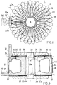
- Fig. 8
- a segment choke in plan view,
- Fig. 9
- 8 a vertical section through the segment throttle according to FIG. 8 with pressure bandage and clamping plates,
- Fig. 10
- 8 is a perspective illustration of a segment of the segment throttle according to FIG. 8,
- Fig. 11
- an insulating film of the segment choke according to FIGS. 8 and
- Fig. 12
- a section of a partial winding in extensive training.
In Fig. 1 ist mit (1) eine ausschnittsweise dargestellte Toroiddrossel bezeichnet, die aus mehreren U-förmigen Wicklungselementen bzw. segmentierten Teilwicklungen (2) aufgebaut ist. Die Teilwicklungen (2) sind ringförmig um eine zentrale, zylinderförmige Aussparung (6) angeordnet und weisen je einen unteren Schenkel (2a) und einen oberen Schenkel (2b) auf. Am Innenrand (4) weisen die Teilwicklungen (2) eine Breite a auf, die kleiner als eine Breite b an ihrem Aussenrand (5) ist. Die beiden Schenkel (2a, 2b) besitzen nahe dem Innenrand (4) eine Höhe c, die grösser als ihre Höhe d am Aussenrand (5) ist. Die Breiten a und b sind so bemessen, dass das verfügbare Volumen für die Toroiddrossel (1) gut ausgenutzt wird. Die zugehörigen Höhen c und d sind so bemessen, dass eine Stromquerschnittsfläche durch jede Teilwicklung (2) gleich ist bzw. nicht mehr als 30 %, vorzugsweise nicht mehr als 10 % von einer mittleren bzw. Soll-Stromquerschnittsfläche abweicht. Am Aussenrand (5) ist der obere Schenkel (2a) einer Teilwicklung (2) jeweils mit dem Aussenrand (5) des unteren Schenkels (2a) einer benachbarten Teilwicklung (2) mittels eines elektrischen Verbindungselementes (3) aus Kupfer z. B. durch Löten elektrisch verbunden. Durch derartige elektrische Verbindungselemente (3) werden die einzelnen Teilwicklungen (2) zu einer einzigen toroidalen Windung verbunden bzw. in Reihe geschaltet. Die Toroiddrossel (1) weist 360/β Teilwicklungen auf, wobei β einen in Grad gemessenen Segmentteilungswinkel bezeichnet.In Fig. 1, (1) denotes a partial toroidal choke, which is constructed from a plurality of U-shaped winding elements or segmented partial windings (2). The partial windings (2) are arranged in a ring around a central, cylindrical recess (6) and each have a lower leg (2a) and an upper leg (2b). At the inner edge (4), the partial windings (2) have a width a that is smaller than a width b on their outer edge (5). The two legs (2a, 2b) have a height c near the inner edge (4) which is greater than their height d on the outer edge (5). The widths a and b are dimensioned so that the available volume for the toroidal choke (1) is used well. The associated heights c and d are dimensioned such that a current cross-sectional area through each partial winding (2) is the same or does not deviate from an average or desired current cross-sectional area by more than 30%, preferably not more than 10%. On the outer edge (5) of the upper leg (2a) of a partial winding (2) each with the outer edge (5) of the lower leg (2a) of an adjacent partial winding (2) by means of an electrical connecting element (3) made of copper z. B. electrically connected by soldering. By Such electrical connecting elements (3) connect the individual partial windings (2) to form a single toroidal turn or connect them in series. The toroidal choke (1) has 360 / β partial windings, where β denotes a segment pitch angle measured in degrees.
Fig. 2 zeigt ausschnittsweise um eine zentrale Aussparung (6) mehrere kreisförmig angeordnete, separate segmentierte Teilwicklungen, wobei zueinander benachbarte Teilwicklungen (7 - 9) in radialer Richtung eine unterschiedliche Länge (1) aufweisen. Durch eine derartige Staffelung lässt sich eine hohe Elementdichte bzw. Windungszahl der Toroiddrossel (1) erreichen. Auf diese Weise kann man bei einem grossen Leiterquerschnitt einen hohen Füllfaktor erhalten.Fig. 2 shows a section around a central recess (6) of several circularly arranged, separate segmented partial windings, with adjacent partial windings (7-9) having a different length (1) in the radial direction. Such a staggering enables a high element density or number of turns of the toroidal choke (1) to be achieved. In this way, a high fill factor can be obtained with a large conductor cross section.
Fig. 3 zeigt ausschnittsweise eine Toroiddrossel (1) mit mehreren Teilwicklungen (10), die in radialer Richtung unterschiedliche Länge und am Aussenrand rechteckige Begrenzungen längs zueinander senkrechter Flächen (11, 12) aufweisen. Auf diese Weise lässt sich die Toroiddrossel (1) an ein vorgegebenes Volumen anpassen. Es versteht sich, dass die Aussenbegrenzung auch z. B. 5eckig, 6eckig usw. gewählt werden könnte.Fig. 3 shows a detail of a toroidal choke (1) with a plurality of partial windings (10) which have different lengths in the radial direction and rectangular boundaries along the perpendicular surfaces (11, 12) on the outer edge. In this way, the toroidal throttle (1) can be adapted to a predetermined volume. It goes without saying that the external boundary also z. B. 5-sided, 6-sided, etc. could be selected.
Fig. 4 zeigt eine U-förmige Teilwicklung (13) mit 2 symmetrischen, gewinkelten Verbindungselementen (13a, 13b), die einen Innenwinkel (α) im Bereich von 90° - 150°, vorzugsweise im Bereich von 100° - 130° zwischen sich einschliessen. Derartige Teilwicklungen (13) können z. B. aus Aluminium oder Kupfer bestehen, als plane Blechschnitte hergestellt und erforderlichenfalls mehrlagig eingesetzt werden.Fig. 4 shows a U-shaped partial winding (13) with 2 symmetrical, angled connecting elements (13a, 13b), which have an inside angle (α) in the range of 90 ° - 150 °, preferably in the range of 100 ° - 130 ° lock in. Such partial windings (13) can, for. B. made of aluminum or copper, made as flat sheet metal cuts and used in multiple layers if necessary.
Fig. 5 zeigt eine Teilwicklung bzw. ein Wicklungselement (14) mit mehreren serpentinartig übereinander angeordneten Windungen, die mittels elektrisch isolierender Distanzstücke bzw. Isolatoren (15) gegenseitig isoliert sind. Die Bezugsziffer (16) bezeichnet einen Anschlussbereich und die Bezugsziffer (17) ein nach aussen umgelegtes und isoliertes Anschlussende.Fig. 5 shows a partial winding or a winding element (14) with several serpentine windings arranged one above the other, which are mutually insulated by means of electrically insulating spacers or insulators (15). The reference number (16) denotes one Connection area and the reference number (17) an externally folded and insulated connection end.
Fig. 6 zeigt eine Teilwicklung (18) in einem Winkelprofil mit abgeschrägten inneren Ecken (18a) und vergrösserten Aussenflächen, die durch Abbiegen aus einem Blechschnitt gewonnen sind. Mit (19) sind Verbindungsbereiche für eine nicht dargestellte Schraubverbindung bezeichnet. Mit ähnlicher Geometrie können auch massive Teilwicklungen (18) z. B. gegossen, gepresst oder tiefgezogen hergestellt sein.Fig. 6 shows a partial winding (18) in an angle profile with chamfered inner corners (18a) and enlarged outer surfaces, which are obtained by bending from a sheet metal cut. (19) denotes connection areas for a screw connection, not shown. With similar geometry, massive partial windings (18) z. B. cast, pressed or deep drawn.
Fig. 7a zeigt eine Teilwicklung (20) aus Litze, die mit einem Wärmeleitharz zu einem kompakten, formbeständigen Element vergossen ist. Mit (21) ist ein Verbindungsprofil bezeichnet. Fig. 7b zeigt eine Schnittansicht längs einer Linie A-A in Fig. 7a. Statt aus Litze kann eine derartige Teilwicklung (20) auch aus einzelnen Blechstreifen durch Verklebung hergestellt sein, wobei die Blechstreifen verröbelt, d. h. verdrillt sind, so dass äussere Blechstreifen zyklisch nach innen und innere nach aussen kommen. Damit wird eine kleine Stromverdrängung erreicht.Fig. 7a shows a partial winding (20) made of stranded wire, which is cast with a thermal resin to form a compact, dimensionally stable element. With (21) a connection profile is designated. Fig. 7b shows a sectional view along a line A-A in Fig. 7a. Instead of stranded wire, such a partial winding (20) can also be produced from individual sheet metal strips by gluing, the sheet metal strips crumpling, i.e. H. are twisted so that the outer sheet metal strips come cyclically inwards and the inner ones outwards. A small current displacement is thus achieved.
Fig. 8 zeigt eine Toroiddrossel (1) mit mehreren jeweils durch Isolierfolien bzw. Isolierschichten (23) getrennten Wicklungssegmenten bzw. Teilwicklungen (22), die kreisförmig um die zentrale Aussparung (6) angeordnet und in ihrer Geometrie besser in Fig. 10 zu erkennen sind. Mit β ist wieder der Segmentteilungswinkel bezeichnet. Am Anfang und Ende der aus 360°/β° Teilwicklungen zusammengesetzten Gesamtwicklung sind 2 separat ausgeführte Stromanschlusselemente (30) bzw. (31) angebracht, die besser in Fig. 9 zu erkennen sind.8 shows a toroidal choke (1) with a plurality of winding segments or partial windings (22), each separated by insulating foils or insulating layers (23), which are arranged in a circle around the central recess (6) and whose geometry can be better seen in FIG. 10 are. The segment pitch angle is again designated with β. At the beginning and end of the overall winding composed of 360 ° / β ° partial windings, 2 separately designed power connection elements (30) and (31) are attached, which can be seen better in FIG. 9.
Das schraffiert dargestellte und nach oben herausgeführte Stromanschlusselement (31) bildet zusammen mit dem gepunktet dargestellten und waagerecht herausgeführten Stromanschlusselement (30) ein Segment, das jedoch, abweichend von den übrigen Segmenten (22), keinen Aussensteg (40) aufweist. Auf Grund der Verschränkung des Segmentes (22) sind die beiden Stromanschlusselemente (30, 31) übereinander angeordnet und, wie auch die anderen Segmente (22), durch eine besser aus Fig. 11 ersichtliche Isolierfolie (23) elektrisch gegenseitig isoliert. Die Isolierfolie (23) ist im in radialer Richtung gesehen äusseren Bereich geschlitzt, so dass sie dort einen oberen und unteren Isolierfolienabschnitt (23a, 23b) aufweist, welche Abschnitte in Fig. 8 aus Gründen besserer Übersichtlichkeit nur im Bereich der Stromanschlusselemente (30, 31) ausgezogen bzw. gepunktet dargestellt sind. Das Stromanschlusselement (30) bildet z. B. den Anfang der Gesamtwicklung und das Stromanschlusselement (31), das z. B. auch waagerecht herausgeführt sein könnte, dessen Ende.The hatched power connection element (31), which is led out upwards, forms a segment together with the power connection element (30), which is shown in dotted lines and is carried out horizontally, but which, unlike the other segments (22), does not Has outer web (40). Due to the interlacing of the segment (22), the two power connection elements (30, 31) are arranged one above the other and, like the other segments (22), are electrically insulated from one another by an insulating film (23) that can be seen better in FIG. 11. The insulating film (23) is slotted in the outer area as seen in the radial direction, so that there it has an upper and lower insulating film section (23a, 23b), which sections in FIG. 8 are only in the area of the power connection elements (30, 31 for reasons of clarity ) are shown in solid lines or dotted lines. The power connector (30) forms z. B. the beginning of the overall winding and the power connector (31), the z. B. could also be led out horizontally, the end.
Fig. 9 zeigt die Toroiddrossel (1) gemäss Fig. 8 in einem senkrechten Querschnitt durch deren Zentrum und zusätzlich einen zentralen Spannbolzen (28) in der Aussparung (6), obere und untere Isolierplatten (25), eine obere scheibenförmige Spannplatte (26), eine untere scheibenförmige Spannplatte (27) und eine elektrisch isoliert angebrachte Druckbandage (29) um den mittleren Teil des Torus, d. h. um einen Aussenrand (41) der Teilwicklungen (22). Die aus Stahl oder aus einem Glasfasermaterial bestehende hochfeste Spannkonstruktion ist so ausgelegt, dass sie den Grossteil der bei einer Stossstrombelastung aufretenden Expansionskräfte der Wicklung aufnehmen kann. (Bei Teilwicklungen aus einfachem Blechschnitt wären die Isolierplatten (25) mit radialen Nuten versehen.)FIG. 9 shows the toroidal choke (1) according to FIG. 8 in a vertical cross section through its center and additionally a central clamping bolt (28) in the recess (6), upper and lower insulating plates (25), an upper disk-shaped clamping plate (26) , a lower disc-shaped clamping plate (27) and an electrically insulated pressure bandage (29) around the middle part of the torus, d. H. around an outer edge (41) of the partial windings (22). The high-strength tensioning structure, made of steel or a glass fiber material, is designed in such a way that it can absorb the majority of the expansion forces of the winding that arise during a surge current load. (In the case of partial windings from a simple sheet metal cut, the insulating plates (25) would be provided with radial grooves.)
Gemäss einer bevorzugten Ausführungsform der Erfindung ist der zentrale Spannbolzen (28) mit scheibenförmigen Spannplatten (26, 27) aus Stahl durch Gewinde verbunden. Der Spannbolzen (28) weist in seinem Inneren einen zentralen Hohlraum bzw. Kühlmittelkanal (28a) auf. Gegenüber den Teilwicklungen (22) ist er durch Isolierringe (24) elektrisch isoliert.According to a preferred embodiment of the invention, the central clamping bolt (28) is connected to steel disc-shaped clamping plates (26, 27) by thread. The clamping bolt (28) has a central cavity or coolant channel (28a) in its interior. It is electrically insulated from the partial windings (22) by insulating rings (24).
Zur Kühlung durch ein Kühlmittel, vorzugsweise Öl, können in einer Teilwicklung (2) ein Kühlmittel-Einströmkanal (34) und ein Kühlmittel-Ausströmkanal (35) vorgesehen sein. Die eingetragenen Pfeile zeigen die Strömungsrichtung des Kühlmittels an. Alternativ dazu kann ein Kühlmittel durch strichpunktiert dargestellte schlitzförmige Öffnungen bzw. Kühlmittel-Einströmkanäle (32) in den Innenraum der Toroiddrossel (1) und von da durch Kühlmittel-Ausströmkanäle (33) und den Kühlmittelkanal (28a) im Inneren des Spannbolzens (28) nach aussen gelangen. Es versteht sich, dass die abzuführende Stromwärme alternativ oder zusätzlich auch mittels nicht dargestellter Kühlrippen an die Umgebung abgeführt werden kann. Mit (39) sind Übergangsstellen zu einer benachbarten, dahinterliegenden Teilwicklung (22) gekennzeichnet.For cooling by a coolant, preferably oil, a coolant inflow channel (34) and a coolant outflow channel (35) can be provided in a partial winding (2). The arrows show the direction of flow of the coolant. As an alternative, coolant can be drawn into the interior of the toroidal throttle (1) through slot-shaped openings or coolant inflow channels (32), and from there through coolant outflow channels (33) and the coolant channel (28a) inside the clamping bolt (28) get outside. It goes without saying that the current heat to be dissipated can alternatively or additionally also be dissipated to the surroundings by means of cooling fins (not shown). With (39) transition points to an adjacent, partial winding (22) lying behind are identified.
Fig. 10 zeigt ein Segment bzw. eine Teilwicklung (22) der Toroiddrossel (1) gemäss Fig. 8 aus einer massiven Windung in einer perspektivischen Ansicht im Detail. Die Teilwicklung (22) weist ein 1. bzw. Anfangsverbindungsstück (36) und ein 2. bzw. Endverbindungsstück (37) mit einer seitlichen, senkrechten Druckanlagefläche (37') und einer waagerechten Anlagefläche (37'') auf, die durch eine Aussparung (38) voneinander beabstandet sind. In diese Aussparung (38) wird beim Zusammenbau der Toroiddrossel (1) der obere Isolierfolienabschnitt (23a) eingeschoben. Der übrige Teil der Isolierfolie (23) dient zur elektrischen Isolierung einer Teilwicklung (22) von der benachbarten, vgl. Fig. 8 und 11. Beim Zusammenbau der Toroiddrossel (1) kommt die in Fig. 8 nicht zu sehende, hintere Druckanlagefläche des Anfangsverbindungsstückes (36) einer Teilwicklung (22) zur Anlage an die Druckanlagefläche (37') der benachbarten Teilwicklung. Durch den Anpressdruck wird eine elektrische Verbindung gewährleistet. Vorzugsweise wird jedoch von der oberen Stirnseite her durch eine hochenergetische Schweissung z. B. mittels eines Elektronen- oder Laserstrahls eine nicht dargestellte Schweissnaht erzeugt, welche eine noch bessere elektrische Verbindung gewährleistet.FIG. 10 shows a segment or a partial winding (22) of the toroidal choke (1) according to FIG. 8 from a solid winding in a perspective view in detail. The partial winding (22) has a 1st or initial connection piece (36) and a 2nd or end connection piece (37) with a lateral, vertical pressure contact surface (37 ') and a horizontal contact surface (37'') through a recess (38) are spaced apart. The upper insulating film section (23a) is pushed into this recess (38) during assembly of the toroidal choke (1). The remaining part of the insulating film (23) serves for the electrical insulation of a partial winding (22) from the neighboring one, cf. 8 and 11. When the toroidal choke (1) is assembled, the rear pressure contact surface of the initial connecting piece (36) of a partial winding (22), which cannot be seen in FIG. 8, comes to rest against the pressure contact surface (37 ') of the adjacent partial winding. An electrical connection is guaranteed by the contact pressure. Preferably, however, from the upper end face by a high-energy welding z. B. by means of an electron or laser beam, not shown Weld seam created, which ensures an even better electrical connection.
Wichtig ist, dass Anfangs- und Endverbindungsstücke (36, 37) zueinander passen bzw. komplementär zueinander ausgebildet sind, so dass bei der Anlage benachbarter Teilwicklungen (22) ein flächenhafter Kontakt gewährleistet ist. Relativ dicke Teilwicklungen (22) können in der gewünschten, gespreizten Form durch Giessen hergestellt werden. Flache Teilwicklungen (22) lassen sich aus einer ringförmigen Scheibe durch Auftrennen längs einer von innen nach aussen führenden Schnittlinie z. B. mittels eines Laserstrahls und durch nachfolgendes Aufbiegen oder Spreizen herstellen. Benachbarte Teilwicklungen (22) werden dann längs dieser Schnittlinien verlötet oder vorzugsweise verschweisst, um eine Gesamtwicklung zu erhalten.It is important that the start and end connecting pieces (36, 37) match one another or are designed to be complementary to one another, so that area contact is ensured when adjacent partial windings (22) are applied. Relatively thick partial windings (22) can be produced in the desired, spread shape by casting. Flat partial windings (22) can be made from an annular disk by cutting along a cutting line leading from the inside outwards, for. B. by means of a laser beam and subsequent bending or spreading. Adjacent partial windings (22) are then soldered or preferably welded along these cutting lines in order to obtain an overall winding.
Fig. 12 zeigt in einem Ausschnitt eine Teilwicklung (39) mit flächiger Ausbildung und vergrösserten Aussenflächen zur Verringerung von Hochfrequenzverlusten. Ein Pfeil (B) zeigt in Richtung der nicht dargestellten Verbindungsstelle.Fig. 12 shows a section of a partial winding (39) with a flat design and enlarged outer surfaces to reduce high-frequency losses. An arrow (B) points in the direction of the connection point, not shown.
Bei Blechschnitten können die Verbindungselemente weichgelötet, hartgelötet oder geschweisst werden. Für massiv ausgeführte Teilwicklungen eignen sich Press- und Schraubverbindungen. Dabei werden die Teilwicklungen (2) der Reihe nach radial in einen nicht dargestellten Wicklungskörper eingeschoben und die Kontaktstellen z. B. mittels Schrauben fixiert.In sheet metal cuts, the connecting elements can be soft-soldered, hard-soldered or welded. Press and screw connections are suitable for solid partial windings. The partial windings (2) are inserted one after the other radially into a winding body, not shown, and the contact points z. B. fixed with screws.
(Nur für die Prüfungstelle bestimmt; nicht Teil der Anmeldung)(Only intended for the examination center; not part of the registration)
- 11
- ToroiddrosselToroidal choke
- 2, 7-10, 13, 18, 22, 392, 7-10, 13, 18, 22, 39
- Teilwicklungen, SegmentePartial windings, segments
- 2a2a
- untere Schenkel von 2lower leg of 2
- 2b2 B
- obere Schenkel von 2upper leg of 2
- 33rd
- elektrisches Verbindungselementelectrical connector
- 44th
- Innenrand von 2Inner edge of 2
- 55
- Aussenrand von 2Outer edge of 2
- 66
- AussparungRecess
- 11, 1211, 12
- rechteckige Aussenbegrenzung, zueinander senkrechte Flächenrectangular outer boundary, surfaces perpendicular to each other
- 13a, 13b13a, 13b
- Verbindungselemente von 13Fasteners from 13
- 1414
- WicklungselementWinding element
- 1515
- Isolation, isolierende DistanzstückeIsolation, insulating spacers
- 1616
- AnschlussbereichConnection area
- 1717th
- isoliertes Anschlussendeinsulated connector end
- 18a18a
- abgeschrägte Ecken von 18bevelled corners of 18
- 1919th
- VerbindungsbereichConnection area
- 2020th
- Teilwicklung aus LitzePartial winding from stranded wire
- 2121
- VerbindungsprofilConnection profile
- 2323
- Isolierschicht, -folieInsulating layer, foil
- 23a23a
- oberer Isolierfolienabschnittupper insulating film section
- 23b23b
- unterer Isolierfolienabschnittlower insulating film section
- 2424th
- IsolierringInsulating ring
- 2525th
- IsolierplatteInsulating plate
- 2626
- obere Spannplatteupper clamping plate
- 2727
- untere Spannplattelower clamping plate
- 2828
- SpannbolzenClamping bolt
- 28a28a
- Hohlraum in 28, KühlmittelkanalCavity in 28, coolant channel
- 2929
- DruckbandagePressure bandage
- 30, 3130, 31
- StromanschlusselementePower connection elements
- 32, 3432, 34
- Kühlmittel-EinströmkanäleCoolant inflow channels
- 33, 3533, 35
- Kühlmittel-AusströmkanäleCoolant outflow channels
- 3636
- 1. bzw. Anfangsverbindungsstück1. or initial connector
- 3737
- 2. bzw. Endverbindungsstück2. or end connector
- 37'37 '
- Druckanlagefläche von 37Print area of 37
- 37''37 ''
- Anlagefläche von 37Investment area of 37
- 3838
- Aussparung für 23Recess for 23
- 3939
- Übergangsstelle zur benachbarten TeilwicklungTransition point to the neighboring partial winding
- 4040
- AussenstegOutside footbridge
- 4141
- Aussenrand von 40 bzw. 22Outside edge of 40 or 22
- A-AA-A
- Schnittcut
- a, ba, b
- Breite von 2Width of 2
- BB
- Pfeilarrow
- c, dc, d
- Höhe von 2aHeight of 2a
- ll
- Länge von 2Length of 2
- αα
- Winkelangle
- ββ
- SegmentierungswinkelSegmentation angle
Claims (10)
Applications Claiming Priority (2)
| Application Number | Priority Date | Filing Date | Title |
|---|---|---|---|
| DE4136176A DE4136176A1 (en) | 1991-11-02 | 1991-11-02 | Toroid thrush |
| DE4136176 | 1991-11-02 |
Publications (2)
| Publication Number | Publication Date |
|---|---|
| EP0540958A1 true EP0540958A1 (en) | 1993-05-12 |
| EP0540958B1 EP0540958B1 (en) | 1996-04-17 |
Family
ID=6443986
Family Applications (1)
| Application Number | Title | Priority Date | Filing Date |
|---|---|---|---|
| EP92118169A Expired - Lifetime EP0540958B1 (en) | 1991-11-02 | 1992-10-23 | Toroidal inductance |
Country Status (3)
| Country | Link |
|---|---|
| EP (1) | EP0540958B1 (en) |
| JP (1) | JPH05283252A (en) |
| DE (2) | DE4136176A1 (en) |
Cited By (4)
| Publication number | Priority date | Publication date | Assignee | Title |
|---|---|---|---|---|
| EP0669629A1 (en) * | 1994-02-25 | 1995-08-30 | Alcatel N.V. | Toroidal transformer |
| US6787599B1 (en) | 1998-05-19 | 2004-09-07 | Ashland-Südchemie-Kernfest GmbH | Alkyl resin emulsions and utilization of the same |
| EP1772877A1 (en) * | 2005-06-02 | 2007-04-11 | STS Spezial-Transformatoren-Stockach GmbH & Co. KG | MF transformer with improved heat dissipation |
| EP2495742A1 (en) * | 2011-02-25 | 2012-09-05 | Sekels Gmbh | High-voltage resistant electricity-compensated interference suppression choke |
Families Citing this family (2)
| Publication number | Priority date | Publication date | Assignee | Title |
|---|---|---|---|---|
| EP2109867A4 (en) * | 2007-01-11 | 2014-12-24 | Keyeye Comm | Wideband planar transformer |
| DE102014005118A1 (en) * | 2014-04-08 | 2015-10-08 | Rosenberger Hochfrequenztechnik Gmbh & Co. Kg | suppression choke |
Citations (7)
| Publication number | Priority date | Publication date | Assignee | Title |
|---|---|---|---|---|
| CH231434A (en) * | 1941-11-04 | 1944-03-15 | Licentia Gmbh | Arrangement for the operation of converters in which a circuit break occurs mechanically. |
| DE937184C (en) * | 1937-12-16 | 1955-12-29 | Siemens Ag | Switching throttle |
| DE1071220B (en) * | 1959-12-17 | Siemens-Schuckertwerke Aktiengesellschaft, Berlin Und Erlangen | Heavy-current choke coil with a ring-shaped iron core, in particular switching choke coil for contact converters | |
| DE1115829B (en) * | 1959-01-16 | 1961-10-26 | Siemens Ag | Heavy current choke coil |
| DE2658774A1 (en) * | 1976-12-24 | 1978-06-29 | Bbc Brown Boveri & Cie | Commutation choke coil for rectifiers - with strands of wire braided to form hose and each strand occupying any position over one turn |
| DE3029650C2 (en) * | 1979-08-06 | 1984-04-26 | Institut elektrosvarki imeni E.O. Patona Akademii Nauk Ukrainskoj SSR, Kiev | Toroidal transformer for resistance butt welding |
| EP0225316A1 (en) * | 1982-01-06 | 1987-06-10 | Kuhlman Corporation | Method and apparatus for winding wedge-shaped segments for an electrical coil of an electrical transformer |
Family Cites Families (3)
| Publication number | Priority date | Publication date | Assignee | Title |
|---|---|---|---|---|
| DE970447C (en) * | 1951-04-14 | 1958-09-18 | Siemens Ag | Choke coil |
| DE1638610C3 (en) * | 1967-09-28 | 1974-02-21 | Siemens Ag, 1000 Berlin U. 8000 Muenchen | Air choke ring coil with variable inductance |
| SU1410118A1 (en) * | 1986-12-30 | 1988-07-15 | Предприятие П/Я А-7866 | Electromagnetic device |
-
1991
- 1991-11-02 DE DE4136176A patent/DE4136176A1/en not_active Withdrawn
-
1992
- 1992-10-23 EP EP92118169A patent/EP0540958B1/en not_active Expired - Lifetime
- 1992-10-23 DE DE59206030T patent/DE59206030D1/en not_active Expired - Fee Related
- 1992-11-02 JP JP4294149A patent/JPH05283252A/en active Pending
Patent Citations (7)
| Publication number | Priority date | Publication date | Assignee | Title |
|---|---|---|---|---|
| DE1071220B (en) * | 1959-12-17 | Siemens-Schuckertwerke Aktiengesellschaft, Berlin Und Erlangen | Heavy-current choke coil with a ring-shaped iron core, in particular switching choke coil for contact converters | |
| DE937184C (en) * | 1937-12-16 | 1955-12-29 | Siemens Ag | Switching throttle |
| CH231434A (en) * | 1941-11-04 | 1944-03-15 | Licentia Gmbh | Arrangement for the operation of converters in which a circuit break occurs mechanically. |
| DE1115829B (en) * | 1959-01-16 | 1961-10-26 | Siemens Ag | Heavy current choke coil |
| DE2658774A1 (en) * | 1976-12-24 | 1978-06-29 | Bbc Brown Boveri & Cie | Commutation choke coil for rectifiers - with strands of wire braided to form hose and each strand occupying any position over one turn |
| DE3029650C2 (en) * | 1979-08-06 | 1984-04-26 | Institut elektrosvarki imeni E.O. Patona Akademii Nauk Ukrainskoj SSR, Kiev | Toroidal transformer for resistance butt welding |
| EP0225316A1 (en) * | 1982-01-06 | 1987-06-10 | Kuhlman Corporation | Method and apparatus for winding wedge-shaped segments for an electrical coil of an electrical transformer |
Cited By (4)
| Publication number | Priority date | Publication date | Assignee | Title |
|---|---|---|---|---|
| EP0669629A1 (en) * | 1994-02-25 | 1995-08-30 | Alcatel N.V. | Toroidal transformer |
| US6787599B1 (en) | 1998-05-19 | 2004-09-07 | Ashland-Südchemie-Kernfest GmbH | Alkyl resin emulsions and utilization of the same |
| EP1772877A1 (en) * | 2005-06-02 | 2007-04-11 | STS Spezial-Transformatoren-Stockach GmbH & Co. KG | MF transformer with improved heat dissipation |
| EP2495742A1 (en) * | 2011-02-25 | 2012-09-05 | Sekels Gmbh | High-voltage resistant electricity-compensated interference suppression choke |
Also Published As
| Publication number | Publication date |
|---|---|
| DE59206030D1 (en) | 1996-05-23 |
| EP0540958B1 (en) | 1996-04-17 |
| DE4136176A1 (en) | 1993-05-06 |
| JPH05283252A (en) | 1993-10-29 |
Similar Documents
| Publication | Publication Date | Title |
|---|---|---|
| DE3101217C2 (en) | Winding for a dry-type transformer with spacer arrangement | |
| DE112017002471T5 (en) | Liquid cooled magnetic element | |
| DE69825047T2 (en) | FLAT MAGNETIC COMPONENT WITH TRANSVERSAL WINDING PATTERN | |
| EP0540958B1 (en) | Toroidal inductance | |
| DE3590224T1 (en) | Power transformer for high speed integrated circuits | |
| EP1722997B1 (en) | Magnetic pole for magnetic levitation vehicles | |
| EP1722998B1 (en) | Magnetic pole for magnetic levitation vehicles | |
| DE4022243A1 (en) | Disc type transformers - has primary and secondary windings set at intervals to ensure that main part of energy passes through windings | |
| EP2079604B1 (en) | Magnet pole for magnetically levitated vehicles | |
| EP0049382B1 (en) | Winding arrangement for transformers with a square cross-sectional core area | |
| EP1501106A1 (en) | Ferrite core for inductive element | |
| DE2344403C3 (en) | Ballast for fluorescent lamps, choke coil or similar inductive device | |
| DE1293334B (en) | High voltage shunt reactor without iron cores | |
| EP0583644B1 (en) | Choke | |
| CH643679A5 (en) | High-current inductor coil | |
| EP3510607B1 (en) | Core for an electrical induction device | |
| DE1239773B (en) | Folded windings for transformers, choke coils and similar induction devices are printed on a band-shaped carrier made of insulating material | |
| DE3918187A1 (en) | Iron core for electromagnetic appliances | |
| EP2330603A1 (en) | Transformer with tape coil | |
| DE2627314C2 (en) | Winding for transformers | |
| WO2000016350A2 (en) | High temperature superconducting transformer | |
| DE3105356A1 (en) | Radially laminated iron core for inductor coils | |
| DE19738946C2 (en) | Choke coil without core | |
| DE2232511C3 (en) | Single or multi-layer high-current winding for transformers | |
| DE2425899B2 (en) | Winding arrangement for transformers with a rectangular core cross-section |
Legal Events
| Date | Code | Title | Description |
|---|---|---|---|
| PUAI | Public reference made under article 153(3) epc to a published international application that has entered the european phase |
Free format text: ORIGINAL CODE: 0009012 |
|
| AK | Designated contracting states |
Kind code of ref document: A1 Designated state(s): DE FR GB IT |
|
| 17P | Request for examination filed |
Effective date: 19931009 |
|
| 17Q | First examination report despatched |
Effective date: 19941222 |
|
| GRAH | Despatch of communication of intention to grant a patent |
Free format text: ORIGINAL CODE: EPIDOS IGRA |
|
| GRAA | (expected) grant |
Free format text: ORIGINAL CODE: 0009210 |
|
| AK | Designated contracting states |
Kind code of ref document: B1 Designated state(s): DE FR GB IT |
|
| REF | Corresponds to: |
Ref document number: 59206030 Country of ref document: DE Date of ref document: 19960523 |
|
| ITF | It: translation for a ep patent filed |
Owner name: DE DOMINICIS & MAYER S.R.L. |
|
| ET | Fr: translation filed | ||
| GBT | Gb: translation of ep patent filed (gb section 77(6)(a)/1977) |
Effective date: 19960628 |
|
| PLBE | No opposition filed within time limit |
Free format text: ORIGINAL CODE: 0009261 |
|
| STAA | Information on the status of an ep patent application or granted ep patent |
Free format text: STATUS: NO OPPOSITION FILED WITHIN TIME LIMIT |
|
| 26N | No opposition filed | ||
| REG | Reference to a national code |
Ref country code: GB Ref legal event code: 732E |
|
| REG | Reference to a national code |
Ref country code: FR Ref legal event code: TP |
|
| REG | Reference to a national code |
Ref country code: GB Ref legal event code: 732E |
|
| REG | Reference to a national code |
Ref country code: FR Ref legal event code: TP |
|
| REG | Reference to a national code |
Ref country code: GB Ref legal event code: IF02 |
|
| PGFP | Annual fee paid to national office [announced via postgrant information from national office to epo] |
Ref country code: GB Payment date: 20020923 Year of fee payment: 11 |
|
| PGFP | Annual fee paid to national office [announced via postgrant information from national office to epo] |
Ref country code: DE Payment date: 20020925 Year of fee payment: 11 |
|
| PGFP | Annual fee paid to national office [announced via postgrant information from national office to epo] |
Ref country code: FR Payment date: 20020926 Year of fee payment: 11 |
|
| PG25 | Lapsed in a contracting state [announced via postgrant information from national office to epo] |
Ref country code: GB Free format text: LAPSE BECAUSE OF NON-PAYMENT OF DUE FEES Effective date: 20031023 |
|
| PG25 | Lapsed in a contracting state [announced via postgrant information from national office to epo] |
Ref country code: DE Free format text: LAPSE BECAUSE OF NON-PAYMENT OF DUE FEES Effective date: 20040501 |
|
| GBPC | Gb: european patent ceased through non-payment of renewal fee |
Effective date: 20031023 |
|
| PG25 | Lapsed in a contracting state [announced via postgrant information from national office to epo] |
Ref country code: FR Free format text: LAPSE BECAUSE OF NON-PAYMENT OF DUE FEES Effective date: 20040630 |
|
| REG | Reference to a national code |
Ref country code: FR Ref legal event code: ST |
|
| PG25 | Lapsed in a contracting state [announced via postgrant information from national office to epo] |
Ref country code: IT Free format text: LAPSE BECAUSE OF NON-PAYMENT OF DUE FEES;WARNING: LAPSES OF ITALIAN PATENTS WITH EFFECTIVE DATE BEFORE 2007 MAY HAVE OCCURRED AT ANY TIME BEFORE 2007. THE CORRECT EFFECTIVE DATE MAY BE DIFFERENT FROM THE ONE RECORDED. Effective date: 20051023 |