EP0224597B1 - Nmr imaging apparatus - Google Patents
Nmr imaging apparatus Download PDFInfo
- Publication number
- EP0224597B1 EP0224597B1 EP86903595A EP86903595A EP0224597B1 EP 0224597 B1 EP0224597 B1 EP 0224597B1 EP 86903595 A EP86903595 A EP 86903595A EP 86903595 A EP86903595 A EP 86903595A EP 0224597 B1 EP0224597 B1 EP 0224597B1
- Authority
- EP
- European Patent Office
- Prior art keywords
- data
- slice
- memory
- converter
- raw data
- Prior art date
- Legal status (The legal status is an assumption and is not a legal conclusion. Google has not performed a legal analysis and makes no representation as to the accuracy of the status listed.)
- Expired - Lifetime
Links
Images


Classifications
-
- G—PHYSICS
- G01—MEASURING; TESTING
- G01R—MEASURING ELECTRIC VARIABLES; MEASURING MAGNETIC VARIABLES
- G01R33/00—Arrangements or instruments for measuring magnetic variables
- G01R33/20—Arrangements or instruments for measuring magnetic variables involving magnetic resonance
- G01R33/44—Arrangements or instruments for measuring magnetic variables involving magnetic resonance using nuclear magnetic resonance [NMR]
- G01R33/48—NMR imaging systems
- G01R33/483—NMR imaging systems with selection of signals or spectra from particular regions of the volume, e.g. in vivo spectroscopy
- G01R33/4833—NMR imaging systems with selection of signals or spectra from particular regions of the volume, e.g. in vivo spectroscopy using spatially selective excitation of the volume of interest, e.g. selecting non-orthogonal or inclined slices
- G01R33/4835—NMR imaging systems with selection of signals or spectra from particular regions of the volume, e.g. in vivo spectroscopy using spatially selective excitation of the volume of interest, e.g. selecting non-orthogonal or inclined slices of multiple slices
Definitions
- the present invention relates to an NMR imaging apparatus which is provided with an improved data acquiring device and which is useful for enhancement of the speed of reconstruction of an image.
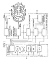
- a conventional NMR imaging apparatus is, as shown in Fig. 4, composed of a static magnetic field coil 2 which is urged by a power source and driver 1 for generating a uniform and stable static magnetic field; a probe head (RF coil) 4 which is urged by the power source and driver 1 for generating an RF pulse, and which detects an NMR signal of an object to be examined and supplies it to a preamplifier and detector 3; a gradient magnetic field coil 5 which is urged by the power source and driver 1 for generating linear gradient magnetic fields in the three directions of x, y and z which overlap the static magnetic field; an A/D converter 14 for converting an output signal of the preamplifier and detector 3 into digital data; and a computer system 6 for controlling the power source and driver 1 and the preamplifier and detector 3 and for processing the digital data supplied from the A/D converter 14.
- the computer system 6 is composed of a central processing unit (CPU) 7, a sequence controller 8, an image display (CRT) 9, a memory (DISK) 10, an array processor (AP) 11 provided with a high-speed memory, an input/output device (I/O) 12, a system bus 13 for connecting these members 7 through 12 to each other, and an A/D converter 14 connected to the I/O 12.
- CPU central processing unit
- sequence controller 8 an image display
- DISK memory
- AP array processor
- I/O input/output device
- system bus 13 for connecting these members 7 through 12 to each other
- A/D converter 14 connected to the I/O 12.
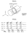
- Fig. 5 schematically shows the relationship between a slice and a view with respect to an object to be examined in the case of acquiring data by a multislice multiecho method (hereinunder an image at the same slice which has a different echo time will be defined as a slice in a broad sense), for example, by the Fourier method by means of such a conventional NMR imaging apparatus.
- the reference numeral 15 represents an object to be examined, and the symbol m represents the number of slices and n the number of views.
- k items of sample data are acquired in one measurement, and such measurement is repeated j times per view in order to obtain the average measured data.
- the operation of the NMR imaging apparatus is as follows.
- the number m of slices is typically 32 and the number j of measurements for averaging is typically 8, but hereinunder it is assumed that the number m of slices is 2, the number n of views 256, the number of items of data 256, and the number j of measurements 2, for the purpose of simplifying the explanation.
- the sequence controller 6 drives the power source and driver 1 at a constant timing on the basis of a command from the CPU 7, the probe head 4 is energized and the current of the gradient magnetic filed coil 5 is turned on and off, as is required for measurement of an NMR signal. It goes without saying that a uniform and static magnetic field has been generated in advance by the static magnetic field coil 2. After the base band of an NMR signal received by the probe head 4 is converted into an audio frequency by the preamplifier and detector 3, the NMR signal is supplied to the A/D converter 14.
- the pulse sequence at this time is carried out in such a manner as is indicated by (a), (b), (c) and (d) in Fig. 6.
- (a), (b), (c) and (d) in Fig. 6 represent the timing for energizing the probe head, and the timings for applying gradient magnetic field in the directions of x, y and z, respectively.
- an NMR signal such as a free induction decay signal (FID signal) indicated by (e) in Fig. 6 is detected.
- FID signal free induction decay signal
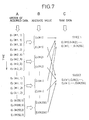
- NMR signals E m (#n, j) are acquired in the order of detection as shown in the column A of Fig. 7, and are stored in the DISK 10 in that order.
- the measured value of an NMR signal Em (#n, j) is composed of k items of sample data.
- the data stored in the DISK 10 are arranged in such a manner that the data measured at a first time at one view are arranged in the order of slices, and the data measured at a second time in the same view are next arranged in the order of slices, and such arrangement is repeated for every view. Therefore, measured data are very complicated with respect to a slice, and the data on the same slice are not collected at the same place.
- the CPU 7 calculates ⁇ E1(#1, 1) + E1(#1, 2) ⁇ /2 to obtain the average value of the data E1 (#1, 1) on the slice 1 measured at first time at a view 1 and the data E1(#1, 2) on the slice 1 measured at a second time at the view 1.
- the average value E1(#1) obtained is re-stored in the DISK 10 as a raw data on the slice 1 at the view 1.
- the CPU 7 executes a similar averaging calculation about all the data on each slice at all the views, and all the average values obtained are subsequently re-stored in the DISK 10.
- the averaged raw data E1(#1), E2(#1), ...E1(#256), E2(#256) are re-stored in the DISK 10 in the order shown in the column B of Fig. 7. In this state, the arrangement of the data is still complicated with respect to a slice.
- the CPU 7 picks up the data E1(#1), E1(#2), ...E1(#256) on the slice 1, for example, from the data stored in this state, as shown in the column C of Fig. 6, and the AP 11 reconstructs the image of the slice 1 on the basis of the collected data.
- the reconstructed image is displayed on the CRT 9.
- the CPU 7 and the AP 11 execute a similar processing on the data E2(#1), E2(#2), ...E2(#256).
- Such a conventional NMR imaging apparatus is disadvantageous in that since measured data are stored in a large-capacity memory in the order of acquisition in a complicated state with respect to a slice, and an image is reconstructed by picking up raw data on the corresponding slice from data stored in such a state, a heavy load is applied to the CPU 7 or the AP 11, so that the speed of reconstruction of an image is lowered.
- an object of the present invention to provide an NMR imaging apparatus which is provided with an improved data acquiring device and which is useful for enhancement of the speed of reconstruction of an image.
- An NMR imaging apparatus is characterized in that a raw data memory 18 which is provided for storing raw data for the maximum number of slices that can be acquired in one scanning separately from the memory of a computer system, and an address converter 19 for converting the addresses of the measured data supplied subsequently in accordance with the sequence of the multislice multiecho method and for storing the measured data in the raw data memory 18 in the arrangement different from the order of acquisition are disposed in a data acquiring device, so that a data block for each slice is formed in the raw data memory.
- Fig. 1 shows the structure of an embodiment of the present invention.
- the reference numeral 16 represents a data acquiring device including the A/D converter 14, and is provided with an averager 17 for averaging the output data of the A/D converter 14, a raw data memory 18 to which the output data of the averager 17 are supplied, and an address converter 19 for supplying an address signal to the averager 17 and the raw data memory 18.
- the address converter 19 converts the addresses of the output data of the A/D converter 14 before storing them in the raw data memory 18, so that the data which are supplied in a complicated order with respect to a slice are stored in each slice area which is provided in the raw data memory 18 in accordance with the slice numbers of the respective data.
- the A/D converter 14, the averager 17 and the address converter 19 are controlled by the sequence controller 8.
- the data of the raw data memory 18 are transferred to the DISK 10 through the I/O 12.
- the sequence controller 8 drives the power source and driver 1 under the control of the CPU 7 in the same way as in the prior art. That is, the following steps (a) to (e) are executed.
- NMR signals indicated by (a) in Fig. 2A are generated by the above-described operation, and are subsequently detected by the probe head 4.
- the detected NMR signals are converted into digital data by the A/D converter 14 and supplied to the averager 17 in the form of a train of data indicated by (b) in Fig. 2A, namely, E1(#1, 1), E2(#1, 1), E1(#1, 2), E2(#1, 2)....
- the averager 17 outputs a first measured data as it is and writes it into the data memory 18, but when the averager 17 fetches a second or later measured data, it reads the preceding measured data from the raw data memory 18 and outputs the average value of the preceding measured data and the data fetched at that time. Such operation of the averager 17 is executed under the control of the sequence controller 8.
- the address for writing and reading measured data is supplied from the address converter 19.
- the data E1(#1, 1) and E2(#1, 1) are subsequently input to the averager 17 in the steps (a) and (b), they are output as they are, and are stored in the address for data E1(#1) in a slice 1 data area and in the address for data E2(#1) in a slice 2 data area, respectively, as shown in Fig. 2B, on the base of the addresses assigned by the address converter 19.
- the respective preceding data E1(#1, 1) and E2(#1, 1) are input from the respective area synchronously with the input of the respective data E1(#1, 2) and E2(#1, 2), and ⁇ E1(#1, 1) + E1(#1, 2) ⁇ /2 and ⁇ E2(#1, 1) + E2(#1, 2) ⁇ /2 are calculated to obtain the respective average values.
- the results of calculation are output and these output data are re-stored in the address for data E1(#1) in the slice 1 data area and in the address for data E2(#1) in the slice 2 data area, respectively, on the basis of the addresses assigned by the address converter 19.
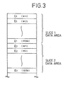
- the raw data memory 18 contains the data E1(#1), E1(#2), ..., E1(#256) in the slice 1 data area, and E2(#1), E2(#2), ..., E2(#256) in the slice 2 data area after one scanning, as shown in Fig. 3.
- data on each slice which are necessary for reconstruction of an image are stored collectively in the area corresponding to the respective slice in the raw data memory 18.
- the raw data memory 18 need not have an area for storing the data measured a plurality of times so long as it is provided with a capacity for storing data for one scanning.
- the data in the raw data memory 18 are transferred to and stored in the DISK 10 while maintaining the arrangement in which data are collected for each slice.
- the AP 11 reads the data necessary for reconstruction of the image from the area in which the data on the desired slice are stored, and conducts a predetermined processing. Since the data necessary for reconstruction of the image are collected in an area for each slice, it is possible to read the data with high efficiency, thereby enabling the image to be reconstructed with a high speed.
- the present invention does not limit the number of views, the number of slices, nor the order of data acquisition to that of this embodiment.
Landscapes
- Physics & Mathematics (AREA)
- Optics & Photonics (AREA)
- Spectroscopy & Molecular Physics (AREA)
- High Energy & Nuclear Physics (AREA)
- Condensed Matter Physics & Semiconductors (AREA)
- General Physics & Mathematics (AREA)
- Magnetic Resonance Imaging Apparatus (AREA)
- Controls And Circuits For Display Device (AREA)
- Image Analysis (AREA)
- Medical Treatment And Welfare Office Work (AREA)
- Image Processing (AREA)
Applications Claiming Priority (2)
| Application Number | Priority Date | Filing Date | Title |
|---|---|---|---|
| JP60128896A JPS61286741A (ja) | 1985-06-13 | 1985-06-13 | Nmrイメ−ジング装置 |
| JP128896/85 | 1985-06-13 |
Publications (3)
| Publication Number | Publication Date |
|---|---|
| EP0224597A1 EP0224597A1 (en) | 1987-06-10 |
| EP0224597A4 EP0224597A4 (en) | 1989-12-28 |
| EP0224597B1 true EP0224597B1 (en) | 1992-12-02 |
Family
ID=14996028
Family Applications (1)
| Application Number | Title | Priority Date | Filing Date |
|---|---|---|---|
| EP86903595A Expired - Lifetime EP0224597B1 (en) | 1985-06-13 | 1986-06-12 | Nmr imaging apparatus |
Country Status (5)
| Country | Link |
|---|---|
| US (1) | US4733187A (enExample) |
| EP (1) | EP0224597B1 (enExample) |
| JP (1) | JPS61286741A (enExample) |
| DE (1) | DE3687218T2 (enExample) |
| WO (1) | WO1986007460A1 (enExample) |
Families Citing this family (4)
| Publication number | Priority date | Publication date | Assignee | Title |
|---|---|---|---|---|
| US5377679A (en) * | 1988-10-27 | 1995-01-03 | Kabushiki Kaisha Toshiba | Magnetic resonance imaging system |
| US5406203A (en) * | 1992-08-10 | 1995-04-11 | The Trustees Of Columbia University In The City Of New York | Methods of multislice acquisition for magnetic resonance imaging |
| JP2713530B2 (ja) * | 1992-08-21 | 1998-02-16 | 株式会社日立製作所 | A/d変換データ処理装置 |
| US9323654B2 (en) | 2013-07-17 | 2016-04-26 | Infineon Technologies Ag | Memory access using address bit permutation |
Family Cites Families (13)
| Publication number | Priority date | Publication date | Assignee | Title |
|---|---|---|---|---|
| US4034191A (en) * | 1974-08-05 | 1977-07-05 | Varian Associates, Inc. | Spectrometer means employing linear synthesized RF excitation |
| JPS589969B2 (ja) * | 1976-05-14 | 1983-02-23 | 日立造船株式会社 | 直接デ−タ転送におけるアドレス制御回路 |
| JPS5322873A (en) * | 1976-08-16 | 1978-03-02 | Hitachi Ltd | Vertical type catalyst-packed apparatus |
| JPS5477042A (en) * | 1977-12-02 | 1979-06-20 | Hitachi Ltd | Data switching input equipment |
| US4355282A (en) * | 1979-08-03 | 1982-10-19 | Picker International Limited | Nuclear magnetic resonance systems |
| DE3370280D1 (en) * | 1982-12-27 | 1987-04-23 | Toshiba Kk | Superposed image display device |
| US4521733A (en) * | 1983-05-23 | 1985-06-04 | General Electric Company | NMR Imaging of the transverse relaxation time using multiple spin echo sequences |
| EP0132337A3 (en) * | 1983-07-21 | 1986-12-30 | The Regents Of The University Of California | Apparatus and method for reducing aliasing in sagittal or coronal nmr imaging |
| JPS6029684A (ja) * | 1983-07-27 | 1985-02-15 | Yokogawa Hokushin Electric Corp | 核磁気共鳴による検査方法及び検査装置 |
| US4573014A (en) * | 1983-11-09 | 1986-02-25 | Duke University | NMR Imaging method and apparatus |
| JPS60190846A (ja) * | 1984-03-10 | 1985-09-28 | Jeol Ltd | 核磁気共鳴装置 |
| US4665365A (en) * | 1985-01-07 | 1987-05-12 | General Electric Company | Method for reversing residual transverse magnetization due to phase-encoding magnetic field gradients |
| JPH0629684A (ja) * | 1992-07-08 | 1994-02-04 | Fujitsu Ltd | シールド筐体 |
-
1985
- 1985-06-13 JP JP60128896A patent/JPS61286741A/ja active Granted
-
1986
- 1986-06-12 DE DE8686903595T patent/DE3687218T2/de not_active Expired - Fee Related
- 1986-06-12 US US07/023,558 patent/US4733187A/en not_active Expired - Fee Related
- 1986-06-12 EP EP86903595A patent/EP0224597B1/en not_active Expired - Lifetime
- 1986-06-12 WO PCT/JP1986/000294 patent/WO1986007460A1/ja not_active Ceased
Also Published As
| Publication number | Publication date |
|---|---|
| EP0224597A1 (en) | 1987-06-10 |
| WO1986007460A1 (fr) | 1986-12-18 |
| JPH0316856B2 (enExample) | 1991-03-06 |
| EP0224597A4 (en) | 1989-12-28 |
| JPS61286741A (ja) | 1986-12-17 |
| DE3687218D1 (de) | 1993-01-14 |
| US4733187A (en) | 1988-03-22 |
| DE3687218T2 (de) | 1993-04-01 |
Similar Documents
| Publication | Publication Date | Title |
|---|---|---|
| US6268730B1 (en) | Multi-slab multi-window cardiac MR imaging | |
| US6144874A (en) | Respiratory gating method for MR imaging | |
| US4521733A (en) | NMR Imaging of the transverse relaxation time using multiple spin echo sequences | |
| EP1113288B1 (en) | Respiratory displacement and velocity measurement using navigator MRI echo signals | |
| US5912557A (en) | Centric phase encoding order for 3D NMR data acquisition | |
| US6294913B1 (en) | Compensation of variations in polarizing magnetic field during magnetic resonance imaging | |
| US6144200A (en) | Acquisition of segmented MRI cardiac data using an EPI pulse sequence | |
| EP1102082B1 (en) | Method and apparatus for reducing image artifacts caused by magnet vibration in an MR imaging system | |
| US6043659A (en) | Magnetic resonance imaging system with non-linear preamplification | |
| EP0224597B1 (en) | Nmr imaging apparatus | |
| US6377831B1 (en) | Real-time MR image subtraction and reconstruction | |
| US4786871A (en) | NMR imaging method and apparatus | |
| US4786872A (en) | NMR imaging method and apparatus | |
| US6278273B1 (en) | MR fluoroscopy with reverse-centric view acquisition | |
| SU1702271A1 (ru) | Способ ЯМР-томографии | |
| US6097977A (en) | Method for controlling data acquisition and image reconstruction during continuous MR imaging | |
| US6008648A (en) | Method for producing physical gradient waveforms in magnetic resonance imaging | |
| SU1644009A1 (ru) | ЯМР - томограф | |
| JP4391214B2 (ja) | 磁気共鳴イメージング装置 | |
| JP2523470B2 (ja) | 核磁気共鳴イメ−ジング方式 | |
| WO1987003464A1 (fr) | Procede d'imagerie par resonance magnetique nucleaire | |
| JP3112926B2 (ja) | 磁気共鳴映像装置 | |
| JPH045951A (ja) | 磁気共鳴イメージング撮影によるデータ収集方法 | |
| US11815583B2 (en) | Echo-spacing shuffling for echo-planar-imaging | |
| JPH08266502A (ja) | Mrイメージング装置 |
Legal Events
| Date | Code | Title | Description |
|---|---|---|---|
| PUAI | Public reference made under article 153(3) epc to a published international application that has entered the european phase |
Free format text: ORIGINAL CODE: 0009012 |
|
| AK | Designated contracting states |
Kind code of ref document: A1 Designated state(s): DE FR GB NL |
|
| 17P | Request for examination filed |
Effective date: 19870616 |
|
| A4 | Supplementary search report drawn up and despatched |
Effective date: 19891228 |
|
| 17Q | First examination report despatched |
Effective date: 19920429 |
|
| GRAA | (expected) grant |
Free format text: ORIGINAL CODE: 0009210 |
|
| AK | Designated contracting states |
Kind code of ref document: B1 Designated state(s): DE FR GB NL |
|
| REF | Corresponds to: |
Ref document number: 3687218 Country of ref document: DE Date of ref document: 19930114 |
|
| ET | Fr: translation filed | ||
| PLBE | No opposition filed within time limit |
Free format text: ORIGINAL CODE: 0009261 |
|
| STAA | Information on the status of an ep patent application or granted ep patent |
Free format text: STATUS: NO OPPOSITION FILED WITHIN TIME LIMIT |
|
| 26N | No opposition filed | ||
| PGFP | Annual fee paid to national office [announced via postgrant information from national office to epo] |
Ref country code: FR Payment date: 19970521 Year of fee payment: 12 |
|
| PGFP | Annual fee paid to national office [announced via postgrant information from national office to epo] |
Ref country code: DE Payment date: 19970522 Year of fee payment: 12 |
|
| PGFP | Annual fee paid to national office [announced via postgrant information from national office to epo] |
Ref country code: NL Payment date: 19970523 Year of fee payment: 12 |
|
| PGFP | Annual fee paid to national office [announced via postgrant information from national office to epo] |
Ref country code: GB Payment date: 19970527 Year of fee payment: 12 |
|
| PG25 | Lapsed in a contracting state [announced via postgrant information from national office to epo] |
Ref country code: GB Free format text: LAPSE BECAUSE OF NON-PAYMENT OF DUE FEES Effective date: 19980612 |
|
| PG25 | Lapsed in a contracting state [announced via postgrant information from national office to epo] |
Ref country code: NL Free format text: LAPSE BECAUSE OF NON-PAYMENT OF DUE FEES Effective date: 19990101 |
|
| GBPC | Gb: european patent ceased through non-payment of renewal fee |
Effective date: 19980612 |
|
| PG25 | Lapsed in a contracting state [announced via postgrant information from national office to epo] |
Ref country code: FR Free format text: LAPSE BECAUSE OF NON-PAYMENT OF DUE FEES Effective date: 19990226 |
|
| NLV4 | Nl: lapsed or anulled due to non-payment of the annual fee |
Effective date: 19990101 |
|
| PG25 | Lapsed in a contracting state [announced via postgrant information from national office to epo] |
Ref country code: DE Free format text: LAPSE BECAUSE OF NON-PAYMENT OF DUE FEES Effective date: 19990401 |
|
| REG | Reference to a national code |
Ref country code: FR Ref legal event code: ST |