EP0224095A2 - Plastic grating, especially one made of recycled plastic - Google Patents
Plastic grating, especially one made of recycled plastic Download PDFInfo
- Publication number
- EP0224095A2 EP0224095A2 EP86115462A EP86115462A EP0224095A2 EP 0224095 A2 EP0224095 A2 EP 0224095A2 EP 86115462 A EP86115462 A EP 86115462A EP 86115462 A EP86115462 A EP 86115462A EP 0224095 A2 EP0224095 A2 EP 0224095A2
- Authority
- EP
- European Patent Office
- Prior art keywords
- grid plate
- grid
- wall
- connecting webs
- plate according
- Prior art date
- Legal status (The legal status is an assumption and is not a legal conclusion. Google has not performed a legal analysis and makes no representation as to the accuracy of the status listed.)
- Granted
Links
Images

Classifications
-
- E—FIXED CONSTRUCTIONS
- E01—CONSTRUCTION OF ROADS, RAILWAYS, OR BRIDGES
- E01C—CONSTRUCTION OF, OR SURFACES FOR, ROADS, SPORTS GROUNDS, OR THE LIKE; MACHINES OR AUXILIARY TOOLS FOR CONSTRUCTION OR REPAIR
- E01C9/00—Special pavings; Pavings for special parts of roads or airfields
- E01C9/08—Temporary pavings
- E01C9/086—Temporary pavings made of concrete, wood, bitumen, rubber or synthetic material or a combination thereof
-
- E—FIXED CONSTRUCTIONS
- E01—CONSTRUCTION OF ROADS, RAILWAYS, OR BRIDGES
- E01C—CONSTRUCTION OF, OR SURFACES FOR, ROADS, SPORTS GROUNDS, OR THE LIKE; MACHINES OR AUXILIARY TOOLS FOR CONSTRUCTION OR REPAIR
- E01C5/00—Pavings made of prefabricated single units
- E01C5/20—Pavings made of prefabricated single units made of units of plastics, e.g. concrete with plastics, linoleum
-
- E—FIXED CONSTRUCTIONS
- E01—CONSTRUCTION OF ROADS, RAILWAYS, OR BRIDGES
- E01C—CONSTRUCTION OF, OR SURFACES FOR, ROADS, SPORTS GROUNDS, OR THE LIKE; MACHINES OR AUXILIARY TOOLS FOR CONSTRUCTION OR REPAIR
- E01C9/00—Special pavings; Pavings for special parts of roads or airfields
- E01C9/10—Steel gratings ; Gratings made of material other than steel
-
- E—FIXED CONSTRUCTIONS
- E02—HYDRAULIC ENGINEERING; FOUNDATIONS; SOIL SHIFTING
- E02D—FOUNDATIONS; EXCAVATIONS; EMBANKMENTS; UNDERGROUND OR UNDERWATER STRUCTURES
- E02D17/00—Excavations; Bordering of excavations; Making embankments
- E02D17/20—Securing of slopes or inclines
- E02D17/205—Securing of slopes or inclines with modular blocks, e.g. pre-fabricated
-
- E—FIXED CONSTRUCTIONS
- E01—CONSTRUCTION OF ROADS, RAILWAYS, OR BRIDGES
- E01C—CONSTRUCTION OF, OR SURFACES FOR, ROADS, SPORTS GROUNDS, OR THE LIKE; MACHINES OR AUXILIARY TOOLS FOR CONSTRUCTION OR REPAIR
- E01C2201/00—Paving elements
- E01C2201/12—Paving elements vertically interlocking
-
- Y—GENERAL TAGGING OF NEW TECHNOLOGICAL DEVELOPMENTS; GENERAL TAGGING OF CROSS-SECTIONAL TECHNOLOGIES SPANNING OVER SEVERAL SECTIONS OF THE IPC; TECHNICAL SUBJECTS COVERED BY FORMER USPC CROSS-REFERENCE ART COLLECTIONS [XRACs] AND DIGESTS
- Y10—TECHNICAL SUBJECTS COVERED BY FORMER USPC
- Y10T—TECHNICAL SUBJECTS COVERED BY FORMER US CLASSIFICATION
- Y10T428/00—Stock material or miscellaneous articles
- Y10T428/16—Two dimensionally sectional layer
Definitions
- the invention relates to a grid plate according to the preamble of claim 1.
- Grid plates made of plastic are already known several times.
- the connection to the adjacent, already laid grid plate consists of tongue and groove.
- the groove can become clogged with long-term storage or improper laying with earth, which makes professional, fast laying considerably more difficult. If stronger horizontal forces occur, a permanent shift of the tongue and groove cannot be ruled out.
- the installed grid panels detach from the composite and form a source of danger.
- the object of the invention is to create a grid plate that can be easily installed, can be locked with the adjacent plate during the installation process and can be easily unlocked again if necessary, which excludes clogging of the locking parts during the installation process and which is simple and inexpensive due to its special design is in the making.
- the connecting webs arranged on a side wall in the upper area of the grid plate serve for mutual anchoring, and are angled at the free end in a hook shape towards the top of the grid plate, while a wall opening in the same position is provided for each connecting web in the opposite side wall of the grid plate.
- the connecting webs of the grid plate to be installed can thus be inserted into the wall openings of the other, already installed grid plate, in such a way that the latter is brought into an inclined position of approximately 30 ° to 45 °. Only in this inclined position can the connecting webs be inserted into the wall openings without touching the floor.
- the hook-shaped bend of the connecting webs can point towards the top of the grid plate.
- the wall openings can be rectangular and the dimensions of the cross section of the plug-in connecting web can be adapted, whereby the mold is significantly simplified.
- the length of the connecting webs up to the hook-shaped bend can be such that the grid plates have a freedom of movement of about 15 mm from or to one another. This makes it possible to compensate for shrinkage and warping after demoulding the grid plates. It is also possible to place the grid plates in a flat circle bow to lay.
- the side wall with the connecting webs can have a continuous cover strip, as a result of which the gap between two adjacent grid plates is covered.
- connecting webs can be arranged directly below the cover strip and molded onto it.
- the connecting webs are much shorter in the free length and, with the same cross section, have a significantly higher moment of resistance to forces acting on them. In addition, they are not so easy to break out of the wall.
- the side wall in the area of the wall openings can be stepped down from the top of the lattice slat, the first step being designed as an abutment for the hook-shaped angled ends of the connecting webs.
- the second stage in connection with the cover strip can cover the gap between adjacent grid plates.
- the wall openings can be laid in the second step side.
- the connecting bars are embedded through the four sides of the wall openings.
- the upper side is covered by the wall part serving as an abutment, the left and the right side by the wall part running parallel to it and the lower side by the wall piece directed towards it. Get the connecting bars this provides particularly good support and guidance, and at the same time the wall openings are well covered.
- the connecting webs with the wall openings and the ribbing on the underside can be arranged such that the grid plate can be divided into two halves. This makes it possible to produce rectangular as well as square grid plates with a single mold.
- the square grid plates are needed as starting pieces when laying in a staggered form. Narrow banquets, e.g. B. at freeway entrances.
- the grid plates are shaken into the soft surface (loose sand).
- the cavities on the underside of the grid plate fill with soil.
- the free ends of the connecting webs can also be angled laterally or downward in the manner of a hook, in which case the grid plate has to be moved laterally for locking without exceeding the scope of the invention.
- the top 2 of the grid plate 1 has a rough non-slip surface, which is penetrated by openings 3.
- the openings 3 allow grass to grow over the floor area 4 covered with lattice battens.
- a ribbing 6 is provided on the underside 5, which gives the grid plate 1 the necessary stiffening and is used for anchoring in the floor.
- connecting webs 8 are arranged, which are angled at the free ends 9 in a hook shape in the direction of the upper side 2. In order to avoid material accumulation in this area, the connecting webs 8 are designed in a U shape lo.
- the connecting webs 8 are also formed on a continuous cover strip 11 which extends over the entire length of the grid plate 1.
- the opposite side wall 12 is stepped towards the bottom 5 and has 8 wall openings 13 in the same position as the connecting webs.
- the wall openings 13 match the cross section of the connecting webs 8.
- the gradation of the side wall 12 is carried out in such a way that the first step results in an abutment 15 for the hook-shaped angled ends 9 of the connecting webs 8.
- the step side 16 parallel to the upper side 2 is covered by the cover strip 11. However, it also serves for lateral guidance and support of the connecting webs 8, which also rest on the lower surface 17 of the wall openings 13 when the grid plates 1 are laid.
- the end faces 18 of the grid plate 1 are smooth.
- a connection to the adjacent grid plate 1 is not necessary here because the grid plates are laid offset to one another.
- the ribbing 6 in the middle of the grid plate is designed such that the grid plate 1 can be divided.
- the half panels serve as end pieces if the grid panels are installed offset.
- the connecting webs 8 can be dimensioned in length so that the grid plates 1 have a freedom of movement of about 15 mm from or to each other. This makes it easy to compensate for shrinkage and discarding of the grid plates 1.
- FIG. 3 shows laid grid plates 1 in the pulled-apart state, while FIG. 4 shows grid plates in the normal, pushed-together state. This game has the further advantage that the grid plates 1 can also be laid in a flat circular arc.
- FIG. 5 shows the laying of grid plates 1.
- the grid plate side with the openings through the wall 13 in a Schräwolf of 3 0 ° is brought to 45 °, whereupon the connecting webs 8 easily into the wall openings 13 have it introduced.
- the hook-shaped angled end 9 of the connecting webs 8 locks and lies against the abutment 15. If laid grid plates are to be dismantled again, the locking can be done by Lift the grid plate 1 again slightly and it can be removed from the wall openings with the connecting webs 8.
Abstract
Die Erfindung betrifft eine Gitterplatte aus Kunstsoff, insbesondere aus Recycling - Kunststoff mit einer rauhen rutschhemmenden Oberseite und einer rippenverstärkten Unterseite. Die einzelnen Gitterplatten werden miteinander durch eine verriegelbare, jedoch wieder lösbare Steckverbindung gehalten. Die Gitterplatten dienen als Befestigungselement für Parkplätze, Straßenbankette, Straßenböschungen u.a.The invention relates to a grid plate made of plastic, in particular made from recycled plastic, with a rough non-slip top and a rib-reinforced bottom. The individual grid plates are held together by a lockable but releasable plug connection. The grid plates serve as a fastening element for parking lots, street banquets, road embankments etc.
Description
Die Erfindung betrifft eine Gitterplatte nach dem Oberbegriff des Anspruchs 1.
Gitterplatten aus Kunststoff sind bereits mehrfach bekannt. Die Verbindung zur benachbarten, bereits verlegten Gitterplatte besteht in einem Falle aus Feder und Nut. Abgesehen davon, daß sich dieselben nach der Entformung beim Abkühlen Über die gesamte Länge verwerfen und nicht mehr einfach ineinanderschiebbar sind, kann sich die Nut bei längerer Lagerung oder unsachgemäßem Verlegen mit Erde zusetzen, wodurch ein fachgemäßes schnelles Verlegen erheblich erschwert wird. Bei Auftreten von stärkeren Horizontalkräften ist ein Verschieben von Feder und Nut auf die Dauer nicht auszuschließen. Die verlegten Gitterplatten lösen sich aus dem Verbund und bilden eine Gefahrenquelle.The invention relates to a grid plate according to the preamble of claim 1.
Grid plates made of plastic are already known several times. In one case, the connection to the adjacent, already laid grid plate consists of tongue and groove. In addition to the fact that they warp over the entire length after removal from the mold when cooling and can no longer be easily pushed into one another, the groove can become clogged with long-term storage or improper laying with earth, which makes professional, fast laying considerably more difficult. If stronger horizontal forces occur, a permanent shift of the tongue and groove cannot be ruled out. The installed grid panels detach from the composite and form a source of danger.
Bei einer anderen bekannten Gitterplatte sind zum gegenseitigen Verbinden glatte, aus der Gitterplatte herausragende Stege vorgesehen, die in entsprechende Ausnehmungen der Gegenseite eingreifen. Die Gitterplatten werden beim Verlegen auf den vorbereiteten Boden gelegt und mit den Stegen in die Ausnehmungen der Gegenplatte geschoben. Dabei gelangt auch Erde in die Ausnehmungen, die sich dadurch zusetzen und das Ineinanderschieben der Gitterplatten erschweren. Oft muß bei diesem Vorgang mit Hammerschlägen nachgeholfen werben. Auch bei diesen Platten läßt sich ein Lösen des Eingriffes durch Horizontalkräfte nicht vermeiden, insbesondere dann, wenn schmale Bankette, wie z. B. an Autobahnauffahrten befestigt werden sollen.In another known grid plate, smooth webs which protrude from the grid plate are provided for mutual connection and engage in corresponding recesses on the opposite side. The grid plates are placed on the prepared floor during installation and pushed into the recesses of the counter plate with the webs. Earth also gets into the recesses, which become clogged and make it difficult to push the grid plates together. Often you have to advertise with hammer blows during this process. These plates can also be loosened Do not avoid grip by horizontal forces, especially when narrow banquets, such as. B. to be attached to freeway entrances.
Aufgabe der Erfindung ist es, eine Gitterplatte zu erstellen, die sich leicht verlegen läßt, sich beim Verlegungsvorgang mit der benachbarten Platte verriegelt und bei Bedarf sich wieder einfach entriegeln läßt, die ein Zusetzen der Verriegelungsteile beim Verlegungsvorgang ausschließt und die durch besondere Formgestaltung einfach und billig in der Herstellung ist.The object of the invention is to create a grid plate that can be easily installed, can be locked with the adjacent plate during the installation process and can be easily unlocked again if necessary, which excludes clogging of the locking parts during the installation process and which is simple and inexpensive due to its special design is in the making.
Diese Aufgabe wird durch den kennzeichnenden Teil des Anspruchs 1 gelöst.
Zur gegenseitigen Verankerung dienen die an einer Seitenwandung im oberen Bereich der Gitterplatte angeordneten Verbindungsstege, die am freien Ende hakenförmig in Richtung zur Oberseite der Gitterplatte abgewinkelt sind, während in der gegenüberliegenden Seitenwandung der Gitterplatte für jeden Verbindungssteg ein Wanddurchbruch in gleicher Position vorgesehen ist. Die Verbindungsstege der zu verlegenden Gitterplatte sind also in die Wanddurchbrüche der anderen, bereits verlegten Gitterplatte einsteckbar, derart, indem dieselbe in eine Schräglage von etwa 30° bis 45° gebracht wird. Nur in dieser Schräglage lassen sich die Verbindungsstege in die Wanddurchbrüche einführen, ohne daß hierbei der Boden berührt wird. Erst nach dem Einführen wird die Gitterplatte in die Verlegungsebene geschwenkt und setzt sich auf dem Boden auf, wobei die Verbindungsstege in den WanddurchbrUchen verriegelt werden. Diese so verriegelte Steckverbindung läßt sich bei einer etwaigen Demontage wieder einfach und leicht lösen, indem diejenige Gitterplatte, die zuletzt verlegt wurde, wieder in die Schräglage angehoben wird, worauf diese durch einfaches Herausziehen wieder abnehmbar ist. Da die Gitterplatten im allgemeinen im Verbund, d.h., versetzt gegeneinander verlegt werden, sind die anderen beideh Seitenwandungen, die nicht zur gegenseitigen Verriegelung dienen, glatt gehalten. Dadurch lassen sich die Formkosten wesentlich verringern und die Produktion der Gitterplatte wird einfacher und billiger. Durch günstige Formgestaltung wird außerdem erreicht, daß auch für die Wanddurchbrüche keine Einlege- oder Ziehkeile benötigt werden und daß sich die Gitterplatte aus der Preßform leicht entfernen läßt.This object is solved by the characterizing part of claim 1.
The connecting webs arranged on a side wall in the upper area of the grid plate serve for mutual anchoring, and are angled at the free end in a hook shape towards the top of the grid plate, while a wall opening in the same position is provided for each connecting web in the opposite side wall of the grid plate. The connecting webs of the grid plate to be installed can thus be inserted into the wall openings of the other, already installed grid plate, in such a way that the latter is brought into an inclined position of approximately 30 ° to 45 °. Only in this inclined position can the connecting webs be inserted into the wall openings without touching the floor. Only after inserting the grid plate is pivoted into the installation level and sits on the floor, the connecting webs are locked in the wall openings. This plug-in connection locked in this way can be easily and easily released again in the event of any disassembly by lifting the grid plate that was last laid back into the inclined position, whereupon this is done by is easy to remove again. Since the lattice panels are generally laid in a composite manner, ie offset from one another, the other two side walls, which are not used for interlocking, are kept smooth. As a result, the molding costs can be significantly reduced and the production of the grid plate becomes easier and cheaper. By favorable shaping is achieved, moreover, that for the W anddurchbrüche no inlay or draw keys are needed and that the grid plate can from the die easily removed.
Nach einem weiteren Merkmal der Erfindung kann die hakenförmige Abwinkelung der Verbindungsstege in Richtung zur Oberseite der Gitterplatte weisen. Dies hat den Vorteil, daß die neu zu verlegende Gitterplatte nur in Schrägstellung bei angehobener Wanddurchbruchseite mit den Verbindungsstegen in die Wanddurchbrüche eingeführt werden kann und daß nach anschließendem Herunterklappen der Gitterplatte in die Verlegungsebene der Haken bzw. die Haken in die Verriegelungswand scharnierartig eingreifen.According to a further feature of the invention, the hook-shaped bend of the connecting webs can point towards the top of the grid plate. This has the advantage that the new grid plate to be installed can only be inserted into the wall openings with the connecting webs in the inclined position with the wall breakthrough side raised, and that after the grid plate has subsequently been folded down, the hook or the hooks engage in the locking wall in a hinge-like manner.
In vorteilhafter Weise können die wanddurchbrüche rechteckförmig ausgebildet und in den Abmessungen dem Querschnitt des einsteckbaren Verbindungssteges angepaßt sein, wodurch die Preßform wesentlich vereinfacht wird.Advantageously, the wall openings can be rectangular and the dimensions of the cross section of the plug-in connecting web can be adapted, whereby the mold is significantly simplified.
Des weiteren können die verbindungsstege bis zur hakenförmigen Abwinkelung in der Länge so bemessen sein, daß den Gitterplatten eine Verschiebefreiheit von etwa 15 mm von- bzw. zueinander gegeben ist. Dadurch lassen sich Schrumpfen und Verwerfen nach der Entformung der Gitterplatten kompensieren. Auch ist damit die Möglichkeit gegeben, die Gitterplatten auch in einem flachen Kreisbogen zu verlegen.Furthermore, the length of the connecting webs up to the hook-shaped bend can be such that the grid plates have a freedom of movement of about 15 mm from or to one another. This makes it possible to compensate for shrinkage and warping after demoulding the grid plates. It is also possible to place the grid plates in a flat circle bow to lay.
Ferner kann die Seitenwandung mit den Verbindungsstegen eine durchgehende Abdeckleiste aufweisen, wodurch der Spalt zwischen zwei benachbarten Gitterplatten abgedeckt wird.Furthermore, the side wall with the connecting webs can have a continuous cover strip, as a result of which the gap between two adjacent grid plates is covered.
Darüber hinaus können die Verbindungsstege unmittelbar unterhalb der Abdeckleiste angeordnet und an dieselbe angeformt sein. Dadurch sind die Verbindungsstege in der freien Länge wesentlich kürzer und haben bei gleichem Querschnitt ein wesentlich höheres Widerstandsmoment gegen auf diese einwirkende Kräfte. Außerdem lassen sich dieselben nicht so leicht aus der Wand herausbrechen.In addition, the connecting webs can be arranged directly below the cover strip and molded onto it. As a result, the connecting webs are much shorter in the free length and, with the same cross section, have a significantly higher moment of resistance to forces acting on them. In addition, they are not so easy to break out of the wall.
In vorteilhafter Weise kann die Seitenwandüng im Bereich der Wanddurchbrüche von der Oberseite der Gitterolatte ausgehend nach unten stufenförmig abgesetzt sein, wobei die erste Stufe als Widerlager für die hakenförmig abgewinkelten Enden der Verbindungsstege ausgebildet ist. Diese Merkmale bewirken eine weitere Vereinfachung der Preßform.Advantageously, the side wall in the area of the wall openings can be stepped down from the top of the lattice slat, the first step being designed as an abutment for the hook-shaped angled ends of the connecting webs. These features further simplify the mold.
Ferner kann die zweite Stufe in Verbindung mit der Abdeckleiste den Spalt zwischen benachbarten Gitterplatten abdecken.Furthermore, the second stage in connection with the cover strip can cover the gap between adjacent grid plates.
Des weiteren können die Wanddurchbrüche in die zweite Stufenseite hineinverlegt sein. Die Verbindungsstege werden hierbei durch die vier Seiten der WanddurchbrUche ringsherum eingebettet. Die Oberseite wird durch das als Widerlager dienende Wandteil abgedeckt, die linke und die rechte Seite durch das parallel dazu verlaufende Wandungsteil und die untere Seite durch das zu dieser gerichtete Wandungsstück. Die Verbindungsstege erhalten dadurch eine besonders gute AbstUtzung und Führung, wobei gleichzeitig die WanddurchbrUche gut abgedeckt sind.Furthermore, the wall openings can be laid in the second step side. The connecting bars are embedded through the four sides of the wall openings. The upper side is covered by the wall part serving as an abutment, the left and the right side by the wall part running parallel to it and the lower side by the wall piece directed towards it. Get the connecting bars this provides particularly good support and guidance, and at the same time the wall openings are well covered.
Schließlich können die Verbindungsstege,mit den Wanddurchbrüchen sowie die unterseitige Verrippung derart angeordnet sein, daß die Gitterplatte in zwei Hälften teilbar ist. Dadurch ist es möglich, mit einer einzigen Preßform rechteckige als auch quadratische Gitterplatten herzustellen. Die quadratischen Gitterplatten werden als Anfangsstücke beim Verlegen in zueinander versetzter Form benötigt. Ebenso können damit auch schmale Bankette,wie z. B. bei Autobahnauffahrten, befestigt werden.Finally, the connecting webs with the wall openings and the ribbing on the underside can be arranged such that the grid plate can be divided into two halves. This makes it possible to produce rectangular as well as square grid plates with a single mold. The square grid plates are needed as starting pieces when laying in a staggered form. Narrow banquets, e.g. B. at freeway entrances.
Nach dem Verlegen werden die Gitterplatten in den weichen Untergrund (loser Sand) eingerüttelt. Dabei füllen sich die Hohlräume an der Unterseite der Gitterplatte mit Erdreich.After laying, the grid plates are shaken into the soft surface (loose sand). The cavities on the underside of the grid plate fill with soil.
Selbstverständlich können die freien Enden der Verbindungsstege auch seitlich oder nach unten hakenförmig abgewinkelt sein, wobei im ersteren Falle die Gitterplatte seitlich zur Verriegelung verschoben werden muß, ohne daß der Rahmen der Erfindung überschritten wird.Of course, the free ends of the connecting webs can also be angled laterally or downward in the manner of a hook, in which case the grid plate has to be moved laterally for locking without exceeding the scope of the invention.
Anhand eines Ausführungsbeispieles, das in der Zeichnung dargestellt ist, soll die Erfindung näher erläutert werden.The invention will be explained in more detail using an exemplary embodiment which is shown in the drawing.
Es zeigen:
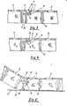
- Fig. 1 einen Querschnitt der Gitterplatte gemäß der Erfindung,
- Fig. 2 eine Teilansicht von oben,
- Fig. 3 einen Teilquerschnitt durch verriegelte Gitterplatten im auseinandergezogenen Zustand,
- Fig. 4 einen Teilquerschnitt durch verriegelte Gitterplatten im normalen Verlegungszustand,
- Fig. 5 einen Querschnitt durch Gitterplatten, die das Einstecken der Verbindungsstege in eine bereits verlegte Gitterplatte veranschaulicht.
- 1 shows a cross section of the grid plate according to the invention,
- 2 is a partial view from above,
- 3 shows a partial cross section through locked grid plates in the pulled-apart state,
- 4 shows a partial cross section through locked grid plates in the normal laying state,
- Fig. 5 shows a cross section through grid plates, which illustrates the insertion of the connecting webs in an already laid grid plate.
Wie aus den Fig. zu erkennen ist, weist die Oberseite 2 der Gitterplatte 1 eine rauhe rutschhemmende Oberfläche auf, die von Durchbrüchen 3 durchbrochen ist. Die Durchbrüche 3 erlauben einen Grasbewuchs der mit Gitternlatten abgedeckten Bodenfläche 4 . An der Unterseite 5 ist eine Verrippung 6 vorgesehen, die der Gitterplatte 1 die notwendige Versteifung gibt und zur Verankerung im Boden dient. An einer Seitenwandung 7 sind Verbindungsstege 8 angeordnet, die an den freien Enden 9 hakenförmig in Richtung zur Oberseite 2 abgewinkelt sind. Um eine Materialanhäufig in diesem Bereich zu vermeiden sind die Verbindungsstege 8 in U-Form lo ausgebildet. Die Verbindungsstege 8 sind außerdem an einer durchgehenden Abdeckleiste 11 angeformt, die sich über die Gesamtlänge der Gitterplatte 1 erstreckt. Die gegenüberliegende Seitenwandung 12 ist zur Unterseite 5 hin stufenförmig abgesetzt und weist in gleicher Position wie die Verbindungsstege 8 Wanddurchbrüche 13 auf. Die Wanddurchbrüche 13 stimmen mit dem Querschnitt der Verbindugsstege 8 überein. Die Abstufung der Seitenwand 12 ist derart ausgeführt, daß die erste Stufe ein widerlager 15 für die hakenförmig abgewinkelten Enden 9 der Verbindungsstege 8 ergibt Die zur Oberseite 2 parallele Stufenseite 16 wird von der Abdeckleiste 11 abgedeckt. Sie dient aber auch zur seitlichen Führung und Abstützung der Verbindungsstege 8, die außerdem bei verlegten Gitterplatten 1 auf der unteren Fläche 17 der Wanddurchbrüche 13 aufliegen. Die Stirnseiten 18 der Gitterplatte 1 sind glatt ausgeführt. Hier ist eine Verbindung mit der benachbarten Gitterplatte 1 nicht erforderlich, weil die Gitterplatten versetzt zueinander verlegt werden. Wie in Fig. 2 zu ersehen ist, ist die Verrippung 6 in der Mitte der Gitterplatte derart gestaltet, daß die Gitterplatte 1 geteilt werden kann. Die halben Platten dienen als Endstücke, wenn die Gitterplatten versetzt verlegt werden.As can be seen from the Fig., The
Die Verbindungsstege 8 können in der Länge so bemessen sein, daß die Gitterplatten 1 eine Verschiebefreiheit von etwa 15 mm von- bzw. zueinander haben. Damit lassen sich Schrumpfen und Verwerfen der Gitterplatten 1 leicht kompensieren. Die Fig. 3 zeigt verlegte Gitterplatten 1 im auseinandergezogen Zustand, während die Fig. 4 Gitterplatten im normalen, zusammengeschobenen Zustand zeigt. Dieses Spiel hat den weiteren Vorteil, daß sich die Gitterplatten 1 auch in einem flachen Kreisbogen verlegen lassen.The connecting
Die Fig. 5 zeigt das Verlegen von Gitterplatten 1. Zum Einstecken der Verbindungsstege 8 in die wanddurchbrüche 13, wird die Gitterplattenseite mit den Wanddurchbrüchen 13 in eine Schrästellung von 30° bis 45° gebracht, worauf sich die Verbindungsstege 8 leicht in die Wanddurchbrüche 13 einführen lassen. Nach dem Herunterschwenken der Gitterplatte 1 von der schrägen in die Verlegungsebene bzw. auf die Bodenfläche 4, verriegelt sich das hakenförmig abgewinkelte Ende 9 der Verbindungsstege 8 und legen sich gegen die Widerlager 15. Sollen verlegte Gitterplatten wieder demontiert werden, so läßt sich die Verriegelung durch Anheben der Gitterplatte 1 wieder leicht lösen und sie kann mit den Verbindungsstegen 8 aus den Wanddurchbrüchen herausgenommen werden.FIG. 5 shows the laying of grid plates 1. For insertion of the connecting
Claims (10)
Applications Claiming Priority (2)
| Application Number | Priority Date | Filing Date | Title |
|---|---|---|---|
| AT0341385A AT388950B (en) | 1985-11-22 | 1985-11-22 | PLASTIC PLATE, ESPECIALLY RECYCLED PLASTIC |
| AT3413/85 | 1985-11-22 |
Publications (3)
| Publication Number | Publication Date |
|---|---|
| EP0224095A2 true EP0224095A2 (en) | 1987-06-03 |
| EP0224095A3 EP0224095A3 (en) | 1988-03-09 |
| EP0224095B1 EP0224095B1 (en) | 1990-10-10 |
Family
ID=3550158
Family Applications (1)
| Application Number | Title | Priority Date | Filing Date |
|---|---|---|---|
| EP86115462A Expired - Lifetime EP0224095B1 (en) | 1985-11-22 | 1986-11-05 | Plastic grating, especially one made of recycled plastic |
Country Status (4)
| Country | Link |
|---|---|
| US (1) | US4826351A (en) |
| EP (1) | EP0224095B1 (en) |
| AT (1) | AT388950B (en) |
| DE (1) | DE3674884D1 (en) |
Cited By (10)
| Publication number | Priority date | Publication date | Assignee | Title |
|---|---|---|---|---|
| DE3837124A1 (en) * | 1988-11-02 | 1989-06-29 | Spiess Kunststoff Recycling | Apertured slab made of plastic, in particular recycled plastic, which can be laid on either side |
| EP0401146A1 (en) * | 1989-06-01 | 1990-12-05 | Pont-A-Mousson S.A. | Fastening means for joining two parts of a traffic area |
| WO1991013208A1 (en) * | 1990-03-02 | 1991-09-05 | Terraplas Limited | Cover for an area of ground |
| WO1992010611A1 (en) * | 1990-12-12 | 1992-06-25 | Sk-Fastening Ltd Oy | Method and mould for casting pavement slabs |
| FR2727139A1 (en) * | 1994-11-23 | 1996-05-24 | Deshayes Dominique | Ground slabs for surrounding and protecting vegetation in urban areas |
| FR2757189A1 (en) * | 1996-12-16 | 1998-06-19 | Reval Plastique | Self-stabilising paved surface of synthetic material |
| WO2003023145A1 (en) | 2001-09-13 | 2003-03-20 | Jerzy Kalisiak | Hexagonal paving panel |
| DE102007035390A1 (en) * | 2007-07-26 | 2009-01-29 | Conradi + Kaiser Gmbh | Floor covering element, floor covering grid and arrangement of floor covering grids, as well as production method of a floor covering grating |
| CN101487218B (en) * | 2009-02-05 | 2010-08-25 | 王强 | Simple road and bridge laying apparatus |
| EP2657401A1 (en) * | 2012-04-26 | 2013-10-30 | Daniel Broghammer | Laying plate |
Families Citing this family (47)
| Publication number | Priority date | Publication date | Assignee | Title |
|---|---|---|---|---|
| US4917532A (en) * | 1985-11-22 | 1990-04-17 | Dr. Spiess Kunstoff-Recycling Gmbh Co. | Grid plate |
| IL89005A (en) * | 1989-01-19 | 1991-11-21 | Polygal | Lightweight construction panels with interconnectable edges |
| US4973505A (en) * | 1989-05-30 | 1990-11-27 | William Bielous | Reversible mat |
| US5098218A (en) * | 1990-07-09 | 1992-03-24 | Bull Dog Construction Co., Inc. | Method and article of manufacture for removable pavement for underground utility placement |
| US5446937A (en) * | 1992-09-08 | 1995-09-05 | Pemko Manufacturing Company | Modular ramp system |
| US5409325A (en) * | 1994-02-10 | 1995-04-25 | Wu; Ming-Hsin | Vinyl walkway paver |
| US5833386A (en) * | 1995-10-25 | 1998-11-10 | Teletek Industries, Inc. | Modular roll-out portable floor and walkway |
| EP0956115A1 (en) * | 1996-10-18 | 1999-11-17 | Variform OY | Protective structure |
| US6032428A (en) * | 1997-10-27 | 2000-03-07 | Ameritech Plastics Incorporated (A Delaware Corporation) | Modular roll-out portable floor for ice surfaces |
| CA2312527A1 (en) * | 2000-06-27 | 2001-12-27 | Lloyd Knafelc | Apparatus for roadways, and the like |
| GB0105803D0 (en) * | 2001-03-09 | 2001-04-25 | Scullion Michael F | Portable outdoor flooring assembly |
| US20030093964A1 (en) * | 2001-10-16 | 2003-05-22 | Bushey Richard D. | Floor grid system |
| DE50110407D1 (en) | 2001-11-02 | 2006-08-17 | Markus Wohler | Slatted frame and fixing mechanism |
| US6802159B1 (en) | 2002-05-31 | 2004-10-12 | Snap Lock Industries, Inc. | Roll-up floor tile system and the method |
| CA2389879A1 (en) * | 2002-06-18 | 2003-12-18 | Lawrence P. Serre | Playstone paver |
| US20050108968A1 (en) * | 2003-06-24 | 2005-05-26 | Sport Court International, Inc. | Arch-ribbed tile system |
| US20070044412A1 (en) * | 2003-06-24 | 2007-03-01 | Forster Cheryl M | Interlocking floorboard tile system and method of manufacture |
| US7748177B2 (en) | 2004-02-25 | 2010-07-06 | Connor Sport Court International, Inc. | Modular tile with controlled deflection |
| US7849642B2 (en) | 2004-03-12 | 2010-12-14 | Connor Sport Court International, Inc. | Tile with wide coupling configuration and method for the same |
| US20070277453A1 (en) * | 2004-10-01 | 2007-12-06 | Trageser Andrew B | Matting for carrying heavy loads over soft soil foundations |
| US8397466B2 (en) * | 2004-10-06 | 2013-03-19 | Connor Sport Court International, Llc | Tile with multiple-level surface |
| US8407951B2 (en) * | 2004-10-06 | 2013-04-02 | Connor Sport Court International, Llc | Modular synthetic floor tile configured for enhanced performance |
| US20090235605A1 (en) * | 2004-10-06 | 2009-09-24 | Thayne Haney | Method of Making A Modular Synthetic Floor Tile Configured For Enhanced Performance |
| US7108454B2 (en) * | 2004-10-12 | 2006-09-19 | Airfield Systems, L.L.C. | Subsurface drainage system and drain structure therefor |
| US20060137268A1 (en) * | 2004-10-18 | 2006-06-29 | Trageser Andrew B | Continuous matting surface |
| USD656250S1 (en) | 2005-03-11 | 2012-03-20 | Connor Sport Court International, Llc | Tile with wide mouth coupling |
| WO2006116450A2 (en) * | 2005-04-22 | 2006-11-02 | Connor Sport Court International, Inc. | Synthetic support base for modular flooring |
| US7587865B2 (en) * | 2005-06-02 | 2009-09-15 | Moller Jr Jorgen J | Modular floor tile with multi level support system |
| US7958681B2 (en) * | 2005-06-02 | 2011-06-14 | Moller Jr Jorgen J | Modular floor tile with nonslip insert system |
| US7571572B2 (en) * | 2005-06-02 | 2009-08-11 | Moller Jr Jorgen J | Modular floor tile system with sliding lock |
| US8099915B2 (en) * | 2005-06-02 | 2012-01-24 | Snapsports Company | Modular floor tile with resilient support members |
| US7300224B2 (en) * | 2005-10-05 | 2007-11-27 | Slater William B | Support grid platform for supporting vehicles over ecologically sensitive terrain |
| US7634876B2 (en) * | 2006-12-08 | 2009-12-22 | Moller Jr Jorgen J | Modular floor locator apparatus |
| US7955025B2 (en) * | 2007-10-02 | 2011-06-07 | Fieldturf Tarkett Inc. | Tile for synthetic grass system |
| JP2010232089A (en) * | 2009-03-27 | 2010-10-14 | Sanyo Electric Co Ltd | Sealed cell |
| GB2475914B (en) * | 2009-12-07 | 2014-03-26 | Kee Safety Ltd | Tread module for a walkway or stairway with severable sub-module portions |
| US8881482B2 (en) | 2010-01-22 | 2014-11-11 | Connor Sport Court International, Llc | Modular flooring system |
| CN102231998B (en) * | 2010-01-22 | 2015-09-09 | 康纳尔运动场国际有限责任公司 | Modular sub-flooring system |
| US8505256B2 (en) * | 2010-01-29 | 2013-08-13 | Connor Sport Court International, Llc | Synthetic floor tile having partially-compliant support structure |
| GB201414866D0 (en) * | 2014-08-21 | 2014-10-08 | Else Robert A | Support component |
| CA2912534C (en) * | 2014-12-02 | 2019-10-22 | Kenneth Szekely | Heatable pathway system for traffic |
| JP6479542B2 (en) * | 2015-04-09 | 2019-03-06 | アルインコ株式会社 | Temporary floorboard equipment |
| US9617698B1 (en) | 2015-12-29 | 2017-04-11 | Stiles Manufacturing, LLC | Permeable paver and modular light system |
| US9909264B1 (en) * | 2015-12-29 | 2018-03-06 | Stiles Manufacturing, LLC | Reconfigurable one piece water permeable paver |
| US9670624B1 (en) * | 2015-12-29 | 2017-06-06 | Stiles Manufacturing, LLC | Double walled earth grabbing water permeable modular paver |
| US9909266B1 (en) * | 2015-12-29 | 2018-03-06 | Stiles Manufacturing, LLC | Reflective and directional water permeable paver system |
| CN108642995A (en) * | 2018-04-18 | 2018-10-12 | 江苏扬天飞龙金属结构制造有限公司 | Combined steel grating easy to install |
Citations (6)
| Publication number | Priority date | Publication date | Assignee | Title |
|---|---|---|---|---|
| DE804960C (en) * | 1949-09-23 | 1951-05-04 | Curt Neubauer | Rods pressed from wood waste or other fillers for floors and other uses |
| US3836075A (en) * | 1972-09-05 | 1974-09-17 | J Botbol | Cleated emergency track |
| US4226064A (en) * | 1977-02-02 | 1980-10-07 | Hans Kraayenhof | Flooring comprising adjoining plastics elements |
| DE2940236A1 (en) * | 1979-07-16 | 1981-01-29 | Weidmann H Ag | FLOORING PANEL |
| EP0117707A2 (en) * | 1983-02-23 | 1984-09-05 | Richard A. Morrison | Mat module with ramp strip |
| DE3327867A1 (en) * | 1983-08-02 | 1985-02-14 | Erich 8151 Neukolbing Weichenrieder sen. | Covering plate which can be assembled to form a plane covering, in particular a hall floor |
Family Cites Families (8)
| Publication number | Priority date | Publication date | Assignee | Title |
|---|---|---|---|---|
| US1509659A (en) * | 1922-04-03 | 1924-09-23 | Milo V Luchich | Paving blocks |
| US2918151A (en) * | 1956-02-15 | 1959-12-22 | Donald S Kennedy | Self-sustaining building unit and wall |
| GB1381324A (en) * | 1972-04-06 | 1975-01-22 | Nayler Petroseals Ltd | Interlockable panels |
| AT325091B (en) * | 1973-01-26 | 1975-10-10 | Staerk Erwin | COUPLING FOR CONTINUOUS SUB-FIELDS |
| AT325093B (en) * | 1973-01-26 | 1975-10-10 | Staerk Erwin | FOOTLAY |
| US4167599A (en) * | 1977-08-16 | 1979-09-11 | Esko Nissinen | Mat and units thereof |
| CH631764A5 (en) * | 1978-07-20 | 1982-08-31 | Kueng Peter Sportfoerderung Ag | Base plate for a covering element for producing a sports ground |
| FR2504400B1 (en) * | 1981-04-23 | 1985-07-12 | See Jacques | PLATES FOR THE CONSTRUCTION OF SPORTS MATS AND PARTICULARLY SKI SLOPES |
-
1985
- 1985-11-22 AT AT0341385A patent/AT388950B/en not_active IP Right Cessation
-
1986
- 1986-11-05 DE DE8686115462T patent/DE3674884D1/en not_active Expired - Lifetime
- 1986-11-05 EP EP86115462A patent/EP0224095B1/en not_active Expired - Lifetime
-
1987
- 1987-11-02 US US07/115,979 patent/US4826351A/en not_active Expired - Fee Related
Patent Citations (6)
| Publication number | Priority date | Publication date | Assignee | Title |
|---|---|---|---|---|
| DE804960C (en) * | 1949-09-23 | 1951-05-04 | Curt Neubauer | Rods pressed from wood waste or other fillers for floors and other uses |
| US3836075A (en) * | 1972-09-05 | 1974-09-17 | J Botbol | Cleated emergency track |
| US4226064A (en) * | 1977-02-02 | 1980-10-07 | Hans Kraayenhof | Flooring comprising adjoining plastics elements |
| DE2940236A1 (en) * | 1979-07-16 | 1981-01-29 | Weidmann H Ag | FLOORING PANEL |
| EP0117707A2 (en) * | 1983-02-23 | 1984-09-05 | Richard A. Morrison | Mat module with ramp strip |
| DE3327867A1 (en) * | 1983-08-02 | 1985-02-14 | Erich 8151 Neukolbing Weichenrieder sen. | Covering plate which can be assembled to form a plane covering, in particular a hall floor |
Cited By (12)
| Publication number | Priority date | Publication date | Assignee | Title |
|---|---|---|---|---|
| DE3837124A1 (en) * | 1988-11-02 | 1989-06-29 | Spiess Kunststoff Recycling | Apertured slab made of plastic, in particular recycled plastic, which can be laid on either side |
| EP0401146A1 (en) * | 1989-06-01 | 1990-12-05 | Pont-A-Mousson S.A. | Fastening means for joining two parts of a traffic area |
| FR2647823A1 (en) * | 1989-06-01 | 1990-12-07 | Pont A Mousson | CONNECTING MEANS FOR JOINING TWO ROOM PARTS |
| WO1991013208A1 (en) * | 1990-03-02 | 1991-09-05 | Terraplas Limited | Cover for an area of ground |
| US5364204A (en) * | 1990-03-02 | 1994-11-15 | Terraplas Limited | Cover for an area of ground |
| WO1992010611A1 (en) * | 1990-12-12 | 1992-06-25 | Sk-Fastening Ltd Oy | Method and mould for casting pavement slabs |
| FR2727139A1 (en) * | 1994-11-23 | 1996-05-24 | Deshayes Dominique | Ground slabs for surrounding and protecting vegetation in urban areas |
| FR2757189A1 (en) * | 1996-12-16 | 1998-06-19 | Reval Plastique | Self-stabilising paved surface of synthetic material |
| WO2003023145A1 (en) | 2001-09-13 | 2003-03-20 | Jerzy Kalisiak | Hexagonal paving panel |
| DE102007035390A1 (en) * | 2007-07-26 | 2009-01-29 | Conradi + Kaiser Gmbh | Floor covering element, floor covering grid and arrangement of floor covering grids, as well as production method of a floor covering grating |
| CN101487218B (en) * | 2009-02-05 | 2010-08-25 | 王强 | Simple road and bridge laying apparatus |
| EP2657401A1 (en) * | 2012-04-26 | 2013-10-30 | Daniel Broghammer | Laying plate |
Also Published As
| Publication number | Publication date |
|---|---|
| US4826351A (en) | 1989-05-02 |
| DE3674884D1 (en) | 1990-11-15 |
| EP0224095B1 (en) | 1990-10-10 |
| ATA341385A (en) | 1989-02-15 |
| AT388950B (en) | 1989-09-25 |
| EP0224095A3 (en) | 1988-03-09 |
Similar Documents
| Publication | Publication Date | Title |
|---|---|---|
| EP0224095A2 (en) | Plastic grating, especially one made of recycled plastic | |
| EP0615566B1 (en) | Set of paving stones, process and device for producing the same | |
| DE2754105C2 (en) | Guideway section for toy vehicles | |
| DE3825446C2 (en) | Barrier to limit lanes, sidewalks or construction sites | |
| EP0816564A2 (en) | Reinforcement for traffic areas with paving elements or slabs | |
| WO2000009808A1 (en) | Paving stone | |
| EP0371917A1 (en) | Capping frame for a drainage channel | |
| DE60101794T2 (en) | ADDITIONAL DEVICE FOR A MODULAR ELEMENT FOR CAVES AND FLOOR STRUCTURES | |
| DE3435909A1 (en) | Lawn stone | |
| DE69530226T2 (en) | INSULATING COMPONENT OR BLOCK. | |
| DE2543829A1 (en) | Fixed length variable width gratings - produced by moulding or casting large width subdivided by partitions or inserts | |
| DE3012855C2 (en) | Bar grating with rectangular grate elements made of plastic | |
| DE7733234U1 (en) | COMPOSITE SILO | |
| DE2219931A1 (en) | FOOT COVERING FOR TENTS, CARAVAN Awnings, etc. | |
| DE1953695A1 (en) | Plastic drawer | |
| EP0007006A1 (en) | Grating for forming duckboards or footscrapers | |
| EP0679763B1 (en) | Paving element | |
| EP0570717A1 (en) | Reinforcing element for connection | |
| DE3641747A1 (en) | Ceramic facade panels, extrusion die for their production and facades produced from panels of this type | |
| DE2425432C3 (en) | Non-load-bearing building partition | |
| DE1934352C3 (en) | Attachment for processes in streets, squares or the like | |
| EP0410035B1 (en) | Box for several drawers | |
| DE2334046C3 (en) | Mold for the production of molded concrete parts with at least one cavity running in the longitudinal direction | |
| EP0033135A1 (en) | Drain or drainage channel with a coverplate of elastic material | |
| EP0498948A1 (en) | Seat and/or step for spectator seating structures |
Legal Events
| Date | Code | Title | Description |
|---|---|---|---|
| PUAI | Public reference made under article 153(3) epc to a published international application that has entered the european phase |
Free format text: ORIGINAL CODE: 0009012 |
|
| AK | Designated contracting states |
Kind code of ref document: A2 Designated state(s): BE CH DE FR GB LI LU NL |
|
| 17P | Request for examination filed |
Effective date: 19870526 |
|
| RAP1 | Party data changed (applicant data changed or rights of an application transferred) |
Owner name: C.F. SPIESS & SOHN KUNSTSTOFFWERK GMBH & CO |
|
| RBV | Designated contracting states (corrected) |
Designated state(s): BE CH DE FR GB LI NL |
|
| RAP1 | Party data changed (applicant data changed or rights of an application transferred) |
Owner name: DR. SPIESS KUNSTSTOFF-RECYCLING GMBH & CO. |
|
| PUAL | Search report despatched |
Free format text: ORIGINAL CODE: 0009013 |
|
| AK | Designated contracting states |
Kind code of ref document: A3 Designated state(s): BE CH DE FR GB LI NL |
|
| 17Q | First examination report despatched |
Effective date: 19890714 |
|
| GRAA | (expected) grant |
Free format text: ORIGINAL CODE: 0009210 |
|
| AK | Designated contracting states |
Kind code of ref document: B1 Designated state(s): BE CH DE FR GB LI NL |
|
| PG25 | Lapsed in a contracting state [announced via postgrant information from national office to epo] |
Ref country code: NL Effective date: 19901010 Ref country code: GB Effective date: 19901010 Ref country code: FR Effective date: 19901010 Ref country code: BE Effective date: 19901010 |
|
| REF | Corresponds to: |
Ref document number: 3674884 Country of ref document: DE Date of ref document: 19901115 |
|
| PG25 | Lapsed in a contracting state [announced via postgrant information from national office to epo] |
Ref country code: LI Effective date: 19901130 Ref country code: CH Effective date: 19901130 |
|
| PG25 | Lapsed in a contracting state [announced via postgrant information from national office to epo] |
Ref country code: DE Effective date: 19901208 |
|
| EN | Fr: translation not filed | ||
| NLV1 | Nl: lapsed or annulled due to failure to fulfill the requirements of art. 29p and 29m of the patents act | ||
| GBV | Gb: ep patent (uk) treated as always having been void in accordance with gb section 77(7)/1977 [no translation filed] | ||
| REG | Reference to a national code |
Ref country code: CH Ref legal event code: PL |
|
| PLBE | No opposition filed within time limit |
Free format text: ORIGINAL CODE: 0009261 |
|
| STAA | Information on the status of an ep patent application or granted ep patent |
Free format text: STATUS: NO OPPOSITION FILED WITHIN TIME LIMIT |
|
| 26N | No opposition filed |