EP0223215B1 - Vorrichtung zum Selektieren und Zuführen von Bandmaterial - Google Patents
Vorrichtung zum Selektieren und Zuführen von Bandmaterial Download PDFInfo
- Publication number
- EP0223215B1 EP0223215B1 EP86115866A EP86115866A EP0223215B1 EP 0223215 B1 EP0223215 B1 EP 0223215B1 EP 86115866 A EP86115866 A EP 86115866A EP 86115866 A EP86115866 A EP 86115866A EP 0223215 B1 EP0223215 B1 EP 0223215B1
- Authority
- EP
- European Patent Office
- Prior art keywords
- web
- draw
- feeding means
- guide unit
- feeding
- Prior art date
- Legal status (The legal status is an assumption and is not a legal conclusion. Google has not performed a legal analysis and makes no representation as to the accuracy of the status listed.)
- Expired - Lifetime
Links
- 239000000463 material Substances 0.000 title claims abstract description 18
- 230000003313 weakening effect Effects 0.000 claims description 3
- 230000001737 promoting effect Effects 0.000 claims description 2
- 230000037431 insertion Effects 0.000 claims 1
- 238000003780 insertion Methods 0.000 claims 1
- 238000004806 packaging method and process Methods 0.000 abstract description 13
- 239000011888 foil Substances 0.000 description 11
- 229920006302 stretch film Polymers 0.000 description 5
- 230000002093 peripheral effect Effects 0.000 description 2
- 238000011144 upstream manufacturing Methods 0.000 description 2
- 238000010276 construction Methods 0.000 description 1
- 235000013305 food Nutrition 0.000 description 1
- 230000005484 gravity Effects 0.000 description 1
- 230000004048 modification Effects 0.000 description 1
- 238000012986 modification Methods 0.000 description 1
Images


Classifications
-
- B—PERFORMING OPERATIONS; TRANSPORTING
- B65—CONVEYING; PACKING; STORING; HANDLING THIN OR FILAMENTARY MATERIAL
- B65B—MACHINES, APPARATUS OR DEVICES FOR, OR METHODS OF, PACKAGING ARTICLES OR MATERIALS; UNPACKING
- B65B41/00—Supplying or feeding container-forming sheets or wrapping material
- B65B41/12—Feeding webs from rolls
- B65B41/16—Feeding webs from rolls by rollers
-
- Y—GENERAL TAGGING OF NEW TECHNOLOGICAL DEVELOPMENTS; GENERAL TAGGING OF CROSS-SECTIONAL TECHNOLOGIES SPANNING OVER SEVERAL SECTIONS OF THE IPC; TECHNICAL SUBJECTS COVERED BY FORMER USPC CROSS-REFERENCE ART COLLECTIONS [XRACs] AND DIGESTS
- Y10—TECHNICAL SUBJECTS COVERED BY FORMER USPC
- Y10T—TECHNICAL SUBJECTS COVERED BY FORMER US CLASSIFICATION
- Y10T225/00—Severing by tearing or breaking
- Y10T225/30—Breaking or tearing apparatus
- Y10T225/307—Combined with preliminary weakener or with nonbreaking cutter
- Y10T225/321—Preliminary weakener
-
- Y—GENERAL TAGGING OF NEW TECHNOLOGICAL DEVELOPMENTS; GENERAL TAGGING OF CROSS-SECTIONAL TECHNOLOGIES SPANNING OVER SEVERAL SECTIONS OF THE IPC; TECHNICAL SUBJECTS COVERED BY FORMER USPC CROSS-REFERENCE ART COLLECTIONS [XRACs] AND DIGESTS
- Y10—TECHNICAL SUBJECTS COVERED BY FORMER USPC
- Y10T—TECHNICAL SUBJECTS COVERED BY FORMER US CLASSIFICATION
- Y10T225/00—Severing by tearing or breaking
- Y10T225/30—Breaking or tearing apparatus
- Y10T225/35—Work-parting pullers [bursters]
-
- Y—GENERAL TAGGING OF NEW TECHNOLOGICAL DEVELOPMENTS; GENERAL TAGGING OF CROSS-SECTIONAL TECHNOLOGIES SPANNING OVER SEVERAL SECTIONS OF THE IPC; TECHNICAL SUBJECTS COVERED BY FORMER USPC CROSS-REFERENCE ART COLLECTIONS [XRACs] AND DIGESTS
- Y10—TECHNICAL SUBJECTS COVERED BY FORMER USPC
- Y10T—TECHNICAL SUBJECTS COVERED BY FORMER US CLASSIFICATION
- Y10T83/00—Cutting
- Y10T83/889—Tool with either work holder or means to hold work supply
- Y10T83/896—Rotatable wound package supply
- Y10T83/902—Plural supply sources
Definitions
- the present invention relates to an apparatus for selecting and feeding web material, which is particularly adapted for being used in the machines for packaging products into sheets of any flexible material, obtained by transversal cutting of a continuous web unreeled from a supply bobbin.
- the invention relates to automatic machines for packaging, by using sheets of stretch film, of products arranged in trays, such as for example food products.
- These machines are capable of packaging products having different sizes, and for this purpose they require stretch film of different widths.
- the object of the present invention is to provide an apparatus for selecting and feeding web material, such as stretch film, from a plurality of supply bobbins of web material presenting different characteristics, to a web utilizing machine, such as a packaging machine, in which the operation of changeover of the web, depending upon the size of the product being packaged, is fully automatic.
- a web utilizing machine such as a packaging machine
- an apparatus for selecting and feeding web material from one of at least two supplies to a web-utilizing station comprising a selecting and dispensing device which draws the web from one of said supplies and can be operatively connected with web feeding means which feed the selected web to the web-utilizing station.
- Said selecting and dispensing device is mounted on supporting means movable with respect to the web feeding means of the utilizing station, and on the supporting means there are mounted two web draw-and-guide units which can be brought into operative alignment with the web feeding means.
- an apparatus for selecting and feeding web material from one of at least two supplies of web material to a web-utilizing machine comprising an selecting and dispensing device which is adapted to selectively draw the web from one of the said supplies and is capable of being operatively connected with web feeding means which feed the selected web to the web-utilizing machine, said selecting and dis- .
- pensing device 'comprising supporting means movable towards and away with respect to the web feeding means, on said supporting means there being mounted at least two web draw-and-guide units which can be selectively brought into operative alignment with the said web feeding means, characterized by the fact that each draw-and-guide unit comprises superposed draw wheels which are kinematically connected so as to consent the feeding of said web material pinched between them, while on the feeding means there is provided a driving wheel which, upon operative engagement of the draw-and-guide unit with the said feeding means, transmits the drive to said superposed draw wheels, in such a manner as to allow unidirectional forward movement of said web material from said supply to the utilizing machine.
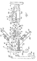
- reference letter T indicates the conveyor feeding means cyclically positioning sheets of a foil web F1, F2, F3 at the packaging station P of a packaging machine said conveyor means T comprising superimposed belts 101, 201 the active runs of which are arranged side by side so as to grip the longitudinal edges of the said web and fold them in a pleated manner whereby the web is clamped firmly betweem them, while being suitably stretched in a transverse direction.
- the belts are suitably spaced apart so as to facilitate the web coming from the draw-and-guide means A1, A2, A3 to enter therebetween.
- the upper wheels R1 are freely rotatable and the lower wheels R2 are keyed to a common shaft which is connected to the driving means for the conveyor means T through a clutch and brake unit (not shown).
- the rings R1 and R2 are in engagement with the foil sheet to be fed to the packaging station of the machine.
- the details of the conveyor feeding means T are not disclosed herein, since they are known for example from US Patent No. 3 662 513.
- the conveyor feeding means of the present invention are modified as follows:
- the shafts 1 and 2 around which the upper belts 101 of the conveyor means T are passed at the lead-in or entry portion of the said conveyor means, are supported at their ends by a pair of parallel plates 3 (only one is visible in Figure 1), which plates 3 are mounted pivotably on shaft 2 and are urged downwardly by gravity or by any suitable elastic or spring means 4.
- At least one of said plates 3 presents a suitably rounded or chamfered edge 103 at its lower front angle, and a rounded recess 203 at an intermediate position of its lower side. The function of the just described plates 3 will be discussed later.
- the selecting and dispensing device Upstream of the conveyor feeding means T there is arranged the selecting and dispensing device, which comprises a slide 7 movable on horizontal guide rods 8 which are perpendicular to the shafts 1 and 2 and are secured to the frame of the packaging machine. Parallel to said rods 8 there is arranged a worm screw 9 which can be rotated in either direction through suitable driving means (not shown). The screw 9 cooperates with a screwnut 12 secured to the slide 7 and which is moved in rectilinear direction, in response to the clockwise or anticlockwise rotation of the screw 9, toward and away with respect to the said conveyor means T.
- a shaft 13 which is arranged parallel to the shafts 1 and 2 of the conveyor means T, said shaft 13 being connected to means (not shown) for promoting its rotation in both directions.
- the shaft 13 can be rotated and locked at predetermined angular positions, so as to act as an indexing device.
- a pair of similar and oppositely arranged plates 18 (only one being shown in Figure 1) are secured perpendicularly to shaft 13.
- the plates 18 are provided, integrally or by suitable attachment means, with pairs of oppositely arranged extensions 118, 218, 318 which are suitably angularly spaced with respect to each other, for example of 45°.
- Said extensions 118, 218, 318 carry the respective draw-and-guide units A1, A2, A3 for the different foil webs F1, F2, F3 unreeled from respective rolls B1, B2 B3 which are mounted on the frame of the packaging machine. Since the web draw-and-guide units A1, A2, A3 are identical to each other, only one of them will be now described (see particularly Figures 1 and 2).
- Each draw-and-guide unit comprises a pair of parallel shafts 19, 20 journalled at their ends on the extensions 118 and having keyed thereto respectively, two small draw wheels 21, 22 of the same diameter and spaced from each other.
- Applied on said wheels 21, 22 are auxiliary draw wheels 121, 122 mounted on the shafts 23, 24 which are supported by parallel plates 25, pivoted at 26 to said plates 18 and provided with scews 27 for connection to said extensions 118.
- scews 27 By loosening the scews 27 said plates 25 can be lifted from said extensions 118 so that the wheels 121, 122 are lifted from the wheels 21, 22 and the leading edge of the foil web F1 to be handled by the unit can be inserted therebetween.
- the shafts 23, 24 are connected by a toothed belt 28 and toothed pulleys 29, 129 having the same diameter.
- These toothed wheels are dimensioned so that the wheels 21, 22 and 121, 122 will rotate with the same peripheral speed.
- the toothed wheel 31 is preferably of the unidirectional type so as to permit the shafts 20, 24, - 23, 19 to rotate only in one direction thus ensuring the proper positioning of the leading edge of the foil web between the draw wheels.
- the pair of superimposed flat-shaped guides 32, 132 through which the foil web is passed and which present a comb-like configuration at both their front and rear portion.
- the rear comb-like portion extends in part upstream of the pair of wheels 22, 122 while the front comb-like portion extends in such a manner so as to enable said guides 32, 132 to exert their guiding action on the foil web while the same is pinched between the conveyor means T, as it will be seen after.
- the rear ends of the said guides 32, 132 are located at a short distance from a transverse counterknife 33 secured to the plates 25 and provided with a longitudinal bottom groove 34, said counterknife being arranged in such a manner that the film running between the pairs of draw wheels 21, 121 and 22, 122 will slide against said grooved bottom.
- rollers 35, 135, 235 supported by the frame of the machine, will guide foil webs F1, F2, F3 presenting different characteristics unreeled from the supply rolls B1, B2, B3, while further rollers 36 and 136 mounted, respectively, coaxially to shaft 13 and on plates 18 are suitably arranged in order to prevent the contact of the foil webs between one another upon angular movement of the selecting and dispensing device whenever changing the film being supplied.
- a roller 37 is provided, which is mounted in cantilever fashion on the outer side of at least one of the extensions 118 (218,318) of each draw-and-guide unit, and which is arranged on the same imaginary vertical plane containing the plates 3 provided with the recess 203 on its lower side.
- the apparatus When at rest, the apparatus is in the condition shown in Figure 1, with the slide 7 at the maximum distance from the feeding means T.
- this condition under control of automatic devices detecting the size of the item to be packaged, or under selective command of the operator, there is automatically selected and prearranged for feeding to the conveyor means T the particular web F1, or F2, or F3 having the required dimensional or other characteristics.
- the desired draw-and-guide unit A1 or A2 or A3 is positioned horizontally.
- the driving means for rotating the screw 9 are actuated, and the slide 7 is caused to move to the right as clearly illustrated in the sequence of Figures 1, 2, 3 and 4.
- the roller 37 engages the bottom side of the plate (or plates) 3 and lifts said plates 3 thus moving apart or opening the initial section of the conveyor means T, R1, R2.
- the leading edge of the foil web F1 can be therefore introduced thereinto while being held fast within the guide means 32, 132.
- the roller 37 reaches the recess 203 ( Figure 4)
- the plates 3 will be lowered, the belts 101, 201 of the conveyor means 7 will close again and the rings R1, R2 will grip the leading edge of the web F1 at the portions which are left free by the comb-like configuration of the guides 32, 132.
- the unidirectional toothed wheels 31 reaches and meshes with a toothed wheel 38 connected to drive means (not shown) which are energized in combination with the conveyor means T, R1, R2.
- the active runs of the belts 101, 201 of the said conveyor means T move rightwards, in the same direction in which the web is moved by the draw wheels 21, 121 and 22, 122 and by the rings R1, R2.
- the linear speed of the belts of the conveyor means T is slightly higher than the peripheral speed of the draw wheels so as to keep the foil web in a suitably stretched condition.
- a notched knife 39 is temporarily lifted so as to penetrate into the groove 34 and to transversally weaken (as known in the art) the said film. Thereafter, when the weakening line has moved downstream of the wheels provided with the rings R1, R2, these wheels and the preceding draw wheels 21, 121, 22, 122 are stopped so that the web F1 will be severed along said weakening line due to the longitudinal tension applied thereto by the belts 101, 201 of the conveyor means T, which will continue to operate to introduce properly the cut off sheet of web into the packaging station P of the machine.
Landscapes
- Engineering & Computer Science (AREA)
- Mechanical Engineering (AREA)
- Auxiliary Devices For And Details Of Packaging Control (AREA)
- Basic Packing Technique (AREA)
- Replacement Of Web Rolls (AREA)
- Advancing Webs (AREA)
- Containers And Plastic Fillers For Packaging (AREA)
- Sewing Machines And Sewing (AREA)
Claims (7)
Priority Applications (1)
| Application Number | Priority Date | Filing Date | Title |
|---|---|---|---|
| AT86115866T ATE49391T1 (de) | 1985-11-19 | 1986-11-14 | Vorrichtung zum selektieren und zufuehren von bandmaterial. |
Applications Claiming Priority (2)
| Application Number | Priority Date | Filing Date | Title |
|---|---|---|---|
| IT1260185 | 1985-11-19 | ||
| IT12601/85A IT1188062B (it) | 1985-11-19 | 1985-11-19 | Distributore per l alimentazione automatica di film di diverse caratteristiche ad una macchina confezionatrice |
Publications (2)
| Publication Number | Publication Date |
|---|---|
| EP0223215A1 EP0223215A1 (de) | 1987-05-27 |
| EP0223215B1 true EP0223215B1 (de) | 1990-01-10 |
Family
ID=11142075
Family Applications (1)
| Application Number | Title | Priority Date | Filing Date |
|---|---|---|---|
| EP86115866A Expired - Lifetime EP0223215B1 (de) | 1985-11-19 | 1986-11-14 | Vorrichtung zum Selektieren und Zuführen von Bandmaterial |
Country Status (7)
| Country | Link |
|---|---|
| US (1) | US4825622A (de) |
| EP (1) | EP0223215B1 (de) |
| JP (1) | JPH0645368B2 (de) |
| AT (1) | ATE49391T1 (de) |
| CA (1) | CA1280775C (de) |
| DE (1) | DE3668153D1 (de) |
| IT (1) | IT1188062B (de) |
Families Citing this family (21)
| Publication number | Priority date | Publication date | Assignee | Title |
|---|---|---|---|---|
| US5312031A (en) * | 1991-07-08 | 1994-05-17 | Nigrelli Systems Inc. | Sheet feeder |
| US5134835A (en) * | 1991-11-04 | 1992-08-04 | Clamco Corporation | Film wrapping apparatus |
| DE69211980T2 (de) * | 1992-02-18 | 1997-01-16 | Sasib Packaging Italia Srl | Maschine zur Herstellung von Kunststoffbeuteln mit Mittel zum Ausrichten der Endkante eines ablaufenden Bandes mit der Anfangskante eines neuen Bandes |
| US5505148A (en) * | 1992-07-28 | 1996-04-09 | Mim Industries, Inc. | Side-by-side programmable feed system for supplying strips in a sewing operation |
| US5406872A (en) * | 1992-07-28 | 1995-04-18 | Mim Industries, Inc. | Side-by-side programmable feed system |
| DE4239388B4 (de) * | 1992-11-24 | 2004-07-29 | Heidelberger Druckmaschinen Ag | Verfahren und Vorrichtung zum Zuführen von einseitig mit Schmelzkleber beschichteten Bändern zu einer weiterführenden Transportvorrichtung |
| ES2112131B1 (es) * | 1994-04-29 | 1998-11-01 | Ulma S Coop Ltada | Mejoras introducidas en maquinas envolvedoras de bandejas con film. |
| US6227731B1 (en) * | 1999-10-14 | 2001-05-08 | Eastman Kodak Company | Printing apparatus |
| AU772208B2 (en) * | 2000-10-06 | 2004-04-22 | Northfield Corporation | Web Burster/inserter |
| ITMI20010094A1 (it) * | 2001-01-19 | 2002-07-19 | Testa Engineering S R L | Macchina per l'avvolgimento in rotoli e/o l'imballaggio di rotoli di tessuti e simili |
| US7273142B2 (en) * | 2004-02-17 | 2007-09-25 | Sealed Air Corporation (Us) | Packaging cushion delivery system |
| US7607467B2 (en) * | 2006-01-17 | 2009-10-27 | Cryovac, Inc. | Web dispenser |
| US7540125B2 (en) * | 2007-03-26 | 2009-06-02 | Northfield Corporation | Bursting apparatus and method |
| US8186896B2 (en) * | 2007-07-16 | 2012-05-29 | Cryovac, Inc. | Apparatus and method for printing and dispensing a web |
| DE102008030489A1 (de) * | 2008-06-26 | 2009-12-31 | Krones Ag | Vorrichtung und Verfahren zum Herstellen von Einzelzuschnitten aus einer Folienbahn |
| DK2532492T3 (da) * | 2009-06-08 | 2014-07-28 | Baumüller Nürnberg GmbH | Variabelt falsesystem med lineært drev, især til trykkemaskiner |
| EP3093244B2 (de) | 2015-05-13 | 2022-01-05 | Bizerba SE & Co. KG | Folientransporteinrichtung für eine verpackungsmaschine |
| JP7020189B2 (ja) * | 2018-03-02 | 2022-02-16 | トヨタ自動車株式会社 | フィルム搬送装置、フィルム搬送方法、及びフィルム貼付け装置 |
| EP3587289B1 (de) * | 2018-06-25 | 2020-07-29 | Bizerba SE & Co. KG | Folientransportvorrichtung für eine verpackungsmaschine zum verpacken mit dehnfolie |
| CN112645136A (zh) * | 2020-12-07 | 2021-04-13 | 北京卫星环境工程研究所 | 航天器热控多层自动出料铺设装置 |
| IT202100018821A1 (it) * | 2021-07-15 | 2023-01-15 | Ytd S R L | Svolgitore automatico di materiali flessibili avvolti su bobine e procedimento per alimentare una macchina operatrice con detti materiali flessibili |
Family Cites Families (9)
| Publication number | Priority date | Publication date | Assignee | Title |
|---|---|---|---|---|
| US3182539A (en) * | 1961-03-14 | 1965-05-11 | Jr Lowdon Richard Williams | Paper feeding and cutting machine |
| CH503616A (de) * | 1969-05-20 | 1971-02-28 | Automac Ind Italiana Costruzio | Verfahren und Maschine zur Verpackung von Packstücken in dehnbaren Folien aus Weichkunststoff |
| US3776081A (en) * | 1971-02-04 | 1973-12-04 | Downingtown Division Beloit Co | Wrapper selector and dispenser |
| IT997143B (it) * | 1973-09-21 | 1975-12-30 | Seragnoli Ariosto | Apparecchiatura per produrre da materiale in nastro avvolto in bobina una successione continua di tratti di nastro o fogli partico larmente adatta per alimentare spezzoni di materiale d incarto a macchine incartatrici |
| FI58465C (fi) * | 1979-10-19 | 1981-02-10 | Waertsilae Oy Ab | System foer frammatning av foerpackningsomslag pao stora pappersrullar |
| JPS573526A (en) * | 1980-06-04 | 1982-01-09 | Mitsubishi Electric Corp | Cross current detecting and preventing device |
| US4551962A (en) * | 1981-09-25 | 1985-11-12 | Teraoka Seiko Co., Ltd. | Weighing and packing apparatus |
| US4510731A (en) * | 1982-04-26 | 1985-04-16 | Hobart Corporation | Film wrapping machine including film length selection |
| US4583348A (en) * | 1984-08-10 | 1986-04-22 | Hobart Corporation | Extended film draw for film wrapping machine |
-
1985
- 1985-11-19 IT IT12601/85A patent/IT1188062B/it active
-
1986
- 1986-11-14 AT AT86115866T patent/ATE49391T1/de not_active IP Right Cessation
- 1986-11-14 EP EP86115866A patent/EP0223215B1/de not_active Expired - Lifetime
- 1986-11-14 DE DE8686115866T patent/DE3668153D1/de not_active Expired - Fee Related
- 1986-11-19 CA CA000523373A patent/CA1280775C/en not_active Expired - Fee Related
- 1986-11-19 US US06/932,257 patent/US4825622A/en not_active Expired - Lifetime
- 1986-11-19 JP JP61274219A patent/JPH0645368B2/ja not_active Expired - Lifetime
Also Published As
| Publication number | Publication date |
|---|---|
| JPS62168832A (ja) | 1987-07-25 |
| JPH0645368B2 (ja) | 1994-06-15 |
| US4825622A (en) | 1989-05-02 |
| IT1188062B (it) | 1987-12-30 |
| ATE49391T1 (de) | 1990-01-15 |
| EP0223215A1 (de) | 1987-05-27 |
| IT8512601A0 (it) | 1985-11-19 |
| DE3668153D1 (de) | 1990-02-15 |
| CA1280775C (en) | 1991-02-26 |
Similar Documents
| Publication | Publication Date | Title |
|---|---|---|
| EP0223215B1 (de) | Vorrichtung zum Selektieren und Zuführen von Bandmaterial | |
| US4489900A (en) | Apparatus for automatically cutting and winding sheet material | |
| US5072637A (en) | Apparatus and method for segmenting continuous webs into predetermined lengths | |
| US6223500B1 (en) | Apparatus and method for wrapping compressible articles with a web-like wrapping material | |
| US6230596B1 (en) | Method of and apparatus for conveying flat pieces of a web | |
| EP0119255B1 (de) | Gewebebehandlungsvorrichtung | |
| US4750442A (en) | Cuff production | |
| US5371521A (en) | Packaging machine with thermal imprinter and method | |
| US11542046B2 (en) | Banding and packaging device | |
| US3075325A (en) | Method and apparatus for feeding wrapping material into a wrapping machine | |
| US4530694A (en) | Sheet, or sheet package transport and rotation apparatus, and method | |
| US2751981A (en) | Sheet forming and stacking apparatus | |
| US5673837A (en) | Apparatus for the high speed stacking of paper sheets | |
| US4022091A (en) | Machine for dressing continuous web materials in stretched condition on a plurality of frames | |
| US3715861A (en) | Improvements in a wrapping machine for wrapping cylindrical objects | |
| EP0162628A2 (de) | Faltvorrichtung | |
| JPS64200B2 (de) | ||
| CA2092377C (en) | Packaging machine with thermal imprinter and method | |
| US3122292A (en) | Web feed and severing device | |
| EP1547927A2 (de) | Vorrichtung zum Zuführen und Schneiden eines Bandes in einer Verpackungsmaschine | |
| EP0491666B1 (de) | Mechanismus zum Zuführen und Zerschneiden von Folienbahnen zur Verwendung in automatischen Verpackungsmaschinen | |
| EP0830068A1 (de) | Indexiergerät zur genauen bewegung von einem nahrungsmittel entlang einer produktionslinie | |
| US1953196A (en) | Wrapper feeding mechanism | |
| US3470668A (en) | Shingling bacon process and apparatus | |
| EP0781721B1 (de) | Maschine zum Auslegen von laminaren Produkten |
Legal Events
| Date | Code | Title | Description |
|---|---|---|---|
| PUAI | Public reference made under article 153(3) epc to a published international application that has entered the european phase |
Free format text: ORIGINAL CODE: 0009012 |
|
| AK | Designated contracting states |
Kind code of ref document: A1 Designated state(s): AT BE CH DE ES FR GB GR LI LU NL SE |
|
| 17P | Request for examination filed |
Effective date: 19870806 |
|
| 17Q | First examination report despatched |
Effective date: 19880203 |
|
| GRAA | (expected) grant |
Free format text: ORIGINAL CODE: 0009210 |
|
| AK | Designated contracting states |
Kind code of ref document: B1 Designated state(s): AT BE CH DE ES FR GB GR LI LU NL SE |
|
| PG25 | Lapsed in a contracting state [announced via postgrant information from national office to epo] |
Ref country code: SE Effective date: 19900110 Ref country code: NL Effective date: 19900110 Ref country code: GR Free format text: LAPSE BECAUSE OF FAILURE TO SUBMIT A TRANSLATION OF THE DESCRIPTION OR TO PAY THE FEE WITHIN THE PRESCRIBED TIME-LIMIT Effective date: 19900110 Ref country code: AT Effective date: 19900110 |
|
| REF | Corresponds to: |
Ref document number: 49391 Country of ref document: AT Date of ref document: 19900115 Kind code of ref document: T |
|
| REF | Corresponds to: |
Ref document number: 3668153 Country of ref document: DE Date of ref document: 19900215 |
|
| ET | Fr: translation filed | ||
| PG25 | Lapsed in a contracting state [announced via postgrant information from national office to epo] |
Ref country code: ES Free format text: LAPSE BECAUSE OF FAILURE TO SUBMIT A TRANSLATION OF THE DESCRIPTION OR TO PAY THE FEE WITHIN THE PRESCRIBED TIME-LIMIT Effective date: 19900421 |
|
| NLV1 | Nl: lapsed or annulled due to failure to fulfill the requirements of art. 29p and 29m of the patents act | ||
| PLBE | No opposition filed within time limit |
Free format text: ORIGINAL CODE: 0009261 |
|
| STAA | Information on the status of an ep patent application or granted ep patent |
Free format text: STATUS: NO OPPOSITION FILED WITHIN TIME LIMIT |
|
| PG25 | Lapsed in a contracting state [announced via postgrant information from national office to epo] |
Ref country code: LU Free format text: LAPSE BECAUSE OF NON-PAYMENT OF DUE FEES Effective date: 19901130 |
|
| 26N | No opposition filed | ||
| PGFP | Annual fee paid to national office [announced via postgrant information from national office to epo] |
Ref country code: CH Payment date: 19930129 Year of fee payment: 7 |
|
| PG25 | Lapsed in a contracting state [announced via postgrant information from national office to epo] |
Ref country code: LI Effective date: 19931130 Ref country code: CH Effective date: 19931130 |
|
| REG | Reference to a national code |
Ref country code: GB Ref legal event code: 732E |
|
| REG | Reference to a national code |
Ref country code: FR Ref legal event code: TP Ref country code: FR Ref legal event code: CJ |
|
| REG | Reference to a national code |
Ref country code: CH Ref legal event code: PL |
|
| PGFP | Annual fee paid to national office [announced via postgrant information from national office to epo] |
Ref country code: GB Payment date: 19961105 Year of fee payment: 11 |
|
| PGFP | Annual fee paid to national office [announced via postgrant information from national office to epo] |
Ref country code: FR Payment date: 19971013 Year of fee payment: 12 |
|
| PGFP | Annual fee paid to national office [announced via postgrant information from national office to epo] |
Ref country code: BE Payment date: 19971028 Year of fee payment: 12 |
|
| PGFP | Annual fee paid to national office [announced via postgrant information from national office to epo] |
Ref country code: DE Payment date: 19971031 Year of fee payment: 12 |
|
| PG25 | Lapsed in a contracting state [announced via postgrant information from national office to epo] |
Ref country code: GB Free format text: LAPSE BECAUSE OF NON-PAYMENT OF DUE FEES Effective date: 19971114 |
|
| GBPC | Gb: european patent ceased through non-payment of renewal fee |
Effective date: 19971114 |
|
| PG25 | Lapsed in a contracting state [announced via postgrant information from national office to epo] |
Ref country code: BE Free format text: LAPSE BECAUSE OF NON-PAYMENT OF DUE FEES Effective date: 19981130 |
|
| BERE | Be: lapsed |
Owner name: A.W.A.X. PROGETTAZIONE E. RICERA S.R.L. Effective date: 19981130 |
|
| PG25 | Lapsed in a contracting state [announced via postgrant information from national office to epo] |
Ref country code: FR Free format text: LAPSE BECAUSE OF NON-PAYMENT OF DUE FEES Effective date: 19990730 |
|
| REG | Reference to a national code |
Ref country code: FR Ref legal event code: ST |
|
| PG25 | Lapsed in a contracting state [announced via postgrant information from national office to epo] |
Ref country code: DE Free format text: LAPSE BECAUSE OF NON-PAYMENT OF DUE FEES Effective date: 19990901 |