EP0222658A1 - Motorgetriebene Schraubvorrichtung mit Blockierung der Achse - Google Patents
Motorgetriebene Schraubvorrichtung mit Blockierung der Achse Download PDFInfo
- Publication number
- EP0222658A1 EP0222658A1 EP86402378A EP86402378A EP0222658A1 EP 0222658 A1 EP0222658 A1 EP 0222658A1 EP 86402378 A EP86402378 A EP 86402378A EP 86402378 A EP86402378 A EP 86402378A EP 0222658 A1 EP0222658 A1 EP 0222658A1
- Authority
- EP
- European Patent Office
- Prior art keywords
- spindle
- rotation
- finger
- locking
- manual switching
- Prior art date
- Legal status (The legal status is an assumption and is not a legal conclusion. Google has not performed a legal analysis and makes no representation as to the accuracy of the status listed.)
- Granted
Links
Images


Classifications
-
- B—PERFORMING OPERATIONS; TRANSPORTING
- B25—HAND TOOLS; PORTABLE POWER-DRIVEN TOOLS; MANIPULATORS
- B25B—TOOLS OR BENCH DEVICES NOT OTHERWISE PROVIDED FOR, FOR FASTENING, CONNECTING, DISENGAGING OR HOLDING
- B25B21/00—Portable power-driven screw or nut setting or loosening tools; Attachments for drilling apparatus serving the same purpose
Definitions
- the present invention concerns a portable motorized screwdriver or "electric" screwdriver.
- This type of screwdriver is well known and generally comprises, on a casing designed to be held in the hand, a rotatable tool-bearing spindle that a usually electric motor housed within the casing drives in rotation in a selected screwing or unscrewing direction; to this end there are provided on the casing manually operated switching means for selecting one or other of these directions of rotation and starting and stopping the motor.
- An object of the present invention is to eliminate this risk.
- the invention consists in a portable motorized screwdriver comprising a tool-bearing spindle, drive means adapted to rotate said spindle in respective opposite directions, manual switching means adapted to cause said drive means selectively to rotate said spindle in one or other of said respective opposite directions or to stop said drive means, and locking means adapted to enable or prevent rotation of said spindle, characterized in that said locking means are coupled to said manual switching means in such a way that actuation of said manual switching means to cause said drive means to rotate said spindle in one or other of said respective opposite directions causes said locking means to enable rotation of said spindle at least in said one or other of said respective opposite directions; for example, to this end, when said manual switching means comprise a trigger and a trigger-operated switch, said locking means are coupled to said manual switching means in such a way that actuating said manual switching means to stop said drive means causes said locking means to prevent said spindle rotating in either of said respective opposite directions.
- the locking means are sure to enable rotation of the spindle in this direction once the drive means are started up.
- the locking means are coupled to the manual switching means in such a way that actuating the manual switching means to stop the drive means causes the locking means to prevent the spindle rotating in either of the respective opposite directions; when the drive means are stopped, the motorized screwdriver in accordance with the present invention may therefore be used like an ordinary manual screwdriver, the blade and the handle of which are constrained to rotate together in both directions.
- the locking means are coupled to the manual switching means in such a way that actuating the manual switching means to stop the drive means with a first of the respective opposite directions preselected causes the locking means to prevent rotation of the spindle in the second of the respective opposite directions and to enable rotation of the spindle in the first direction; thus when the drive means are stopped the screwdriver in accordance with the present invention may be used like a manual rachet screwdriver, in a particularly convenient way.
- the transmission system advantageously comprises clutch means that are engaged when the motor is running and disengaged when the motor is stopped, the locking means cooperating with the transmission system on the output side of the clutch means, that is to say between the latter and the spindle; in this way use of the motorized screwdriver like a manual rachet screwdriver does not entail any rotation of the motor, which therefore does not exert any torque resisting rotation of the spindle in the direction authorized by the locking means.
- time-delay means for delaying locking of the spindle relative to stopping of the drive means and for delaying starting of the drive means relative to releasing of the spindle; in this way it is sure that the locking means will never immobilize the spindle before it has completely stopped rotating and that the motor will never begin to operate before the spindle is released by the locking means after a period of immobilization.
- the drive means comprise a direct current electric motor having first and second power supply terminals and the manual switching means comprise means for connecting the first and second terminals of the motor respectively to first and second terminals of a direct current power supply in order to operate the drive means so as to rotate the spindle in one of the respective opposite directions and means for connecting the first and second terminals of the motor respectively to the second and first terminals of the power supply in order to operate the drive means so as to rotate the spindle in the other of the respective opposite directions
- the manual switching means preferably comprise means for connecting the first and second terminals of the motor together and isolating them from at least one of the terminals of the power supply in order to stop the drive means; short-circuiting the two terminals of the direct current motor in this way makes effective provision for braking the motor and consequently stopping it as quickly as possible.
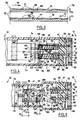
- a rigid casing l of plastics material is formed by assembling together two shells l a and one l b on a plane 2 relative to which the two shells l a and l b are symmetrical to each other; the shell l b and the plane 2 are seen in figures 4 through 8, l0 through l2 and l6 through l8.
- the casing l is generally pistol-shaped and thus comprises: - a body area 3 inside which is accommodated a direct current electric motor 4 having on an axis 5 located in the plane 2 an output shaft 6 adapted to be driven in rotation about the axis 5 in one direction or the other according to how the motor 4 is supplied with electricity, - a hand grip butt area 7 inside which are accommodated electric batteries 8 to supply electricity to the motor 4, the batteries 8 being disposed along a mean axis 9 intersecting an extension of the axis 5 on the opposite side of the motor 4 relative to the output shaft 6; the part of the body 3 surrounding the intersection ll of the axis 5 and the mean axis 9, that is to say the area where the butt 7 merges with the body 3, will be referred to by convention as the "back” l0 whereas the part of the body 3 surrounding in particular the output shaft 6 of the motor, on the opposite side of the motor relative to the back l0 along the axis 5, will be referred to as the "front"
- the casing l also accommodates a circuit l3 for supplying electricity to the motor 4 from the batteries 8;
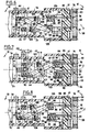
- figure 9 is a schematic of the circuit l3 showing the negative terminal l4 of the batteries 8 connected in series, the positive terminal l5 of the batteries, two terminals l6 and l7 through which the motor 4 is supplied with electricity, and a reversing switch assembly l8 which, as can be seen in figure l, is accommodated in the body 3 where this joins onto the butt 7.
- the reversing switch l8 comprises two single-pole switches l9 and 20 each of which has three aligned terminals, namely a central terminal connected to the terminal l6 of the motor in the case of the single-pole switch l9 and to the terminal l7 of the motor in the case of the single-pole switch 20, and two end terminals, namely a terminal l connected to the negative terminal l4 of the batteries 8 and a terminal 22 connected to the positive terminal l5 of the batteries 8 in the case of the single-pole switch l9 and a terminal 23 connected to the negative terminal l4 of the batteries 8 and a terminal 24 connected to the positive terminal l5 of the batteries 8 in the case of the switch 20;
- the switch l9 includes a slider 25 which slides in a direction parallel to the alignment of the terminals l6, 2l, 22 to establish selectively an electrical connection between the central terminal l6 and either the terminal 2l or the terminal 22; a spring 26 urges the slider 25 into a position where it establishe
- the terminals l6 and l7 of the motor are connected by the sliders 25 and 27 and the terminals 22 and 24 to the same terminal of the battery 8, namely the positive terminal l5 thereof, which short-circuits together the terminals l6 and l7 of the motor 4 and, by virtue of the nature of the motor, immobilizes its output shaft 6 against rotation about the axis 5.
- the switches l9 and 20 are disposed on respective sides of the plane 2, symmetrically to each other with respect to this plane, as is indicated by the schematic representation of the sliders 25 and 27 in figures 4 through 8, l0 through l2 and l6 through l8; to be more precise, in the embodiment described and shown, if it is assumed that the butt 7 is turned downwardly relative to the body 3 and that the screwdriver is observed in the direction from the back l0 towards the front l2 parallel to the axis 5, the switch l9 is situated to the right of the plane 2, the alignment of the terminals 2l, l6, 22 being parallel to this plane and to the axis 5 of the motor with the terminal 22 situated to the front of the terminal l6 in turn situated to the front of the terminal 2l; given the same observation conditions, the switch 20 is situated on the left of the plane 2 and the alignment of the terminals 23, l7, 24 is parallel to this plane and the axis 5, the terminal 24 being situated to the front of the terminal l7
- the trigger 33 In the immediate vicinity of the body 3 the trigger 33 carries a lug 36 carrying a lever 37 which selects the direction of rotation of the shaft 6 of the motor 4, the lever 37 being guided by the lug 36 to rotate relative to the trigger 33 about an axis 38 in the plane 2 and perpendicular to the axis 5 and to the direction 34.
- the lever 37 also visible in figures 4 through 8, l0 through l2 and l6 through l8, has a specific mean direction 39 which, by pivoting of the lever 37 about the axis 38 relative to the trigger 33, may be brought into a position shown in figures l, 4, l0 and l6 in which it is situated in the plane 2; in this so-called “neutral” position the lever 37 features to the front of the axis 38, along its mean direction 39, an area 40 situated outside the casing l and authorising manual actuation of the lever 37 in rotation about the axis 38 relative to the trigger 33; similarly, when in this position the lever 37 features to the rear of the axis 38 a rectilinear part 4l extending into the casing l and featuring, in the direction towards a flat face 42 on the trigger 3 perpendicular to the axis 38, a latching finger 43 urged elastically towards this face 42 along an axis 44 parallel to the axis 38 and fixed relative to the lever 37; in order to receive the finger
- the lever 37 may be moved to two other positions, namely: - a position shown in figures 5, 6, ll and l7 in which the finger 45 is elastically inserted in the depression 48 and achieved by manually moving the part 40 of the lever 37 to the side of the plane 2 corresponding to the slider 25 and to the depression 47; in this position the part 4l of the lever 37 features towards the rear an end face 50 directly facing the slider 27 in a direction 5l parallel to the axis 5 and to the direction 34; if the trigger 33 is in its maximum projection position, the rear end face 50 of the part 4l is then located to the front of the slider 27, at a distance d1 from the latter as measured in the direction 5l; if the trigger 33 is moved to the maximum retracted position with the lever 37 in this position and immediately the trigger 33 has moved over a distance d2 greater than d1 in the direction 34, the rear end face 50 of the part
- releasing the trigger 33 when in its maximum retraction position permits elastic return of the trigger to its maximum projection position and elastic return of the slider 27 to its position making an electrical connection between the terminals l7 and 24 or of the slider 25 to its position making an electrical connection between the terminals l6 and 22.
- the output shaft 6 of the motor 4 has fastened to it a gearwheel 57 which meshes constantly with a toothed wheel 58 disposed to rotate relative to the casing l about an axis 59 fixed relative to the casing l and relative to the toothed wheel 28, disposed parallel to the axis 5 in the plane 2; relative to the casing l, this axis 59 is defined by a bearing 60 on a plate 6l fastened into the casing l generally perpendicularly to the axis 5 and by a bearing l6l situated to the front of the bearing 60 and defined by the casing itself; relative to the toothed wheel 58 the axis 59 is defined by a spindle 26l fastened to a hub part 62 of the toothed wheel 58, which hub part 62 itself carries, through the intermediary of known type centrifugal clutch means 63, a coaxial toothed ring 64 defining the meshing engagement between the wheel 58 and the gearwheel 57;
- the hub part 62 of the wheel 58 is fastened to gearwheel 65 which meshes with a toothed wheel 66 rotatable relative to the casing l about an axis (not shown) parallel to the axes 5 and 59 and fixed relative to the casing l and relative to the toothed wheel 66; the toothed wheel 66 is fastened to a gearwheel 67 which meshes with teeth 68 on the spindle 54 the axis of rotation 55 of which is defined on one side of the teeth 68, that is to say towards the front, by a bearing 69 providing guidance for it where it passes through the casing l and towards the rear by a coupling by means of a coaxial shaft 70 to a bearing 7l of the plate 6l.
- the hub part 62 of the toothed wheel 58, possibly together with the ring 64, and the spindle 54 are mutually coupled to rotate in the same direction, opposite the direction of rotation of the output shaft 6 of the motor 4 if such rotation of the spindle and the toothed wheel results from that of this output shaft; thus rotation of the output shaft 6 in the direction 30, as a result of appropriate supply of power to the motor 4, corresponds to rotation of the spindle 54 and of the toothed wheel 58 in an unscrewing direction 72 whereas rotation of the output shaft 6 in the direction 32 corresponds to rotation of the spindle 54 and of the toothed wheel 58 in the screwing direction 73.
- the hub part 62 of the toothed wheel 58 features a recess on an otherwise flat face 74 perpendicular to the axis 59 and facing towards the rear, that is to say towards the plate 6l.
- the face 74 features on a first circle 75 with axis 59 a plurality of (four in this example) grooves 76 the shape of which is seen more clearly in figure 3 which shows the plane development of a cylindrical cross-section of the hub part 62 on the circle 75 relative to an arbitrarily chosen origin 79; figure 3 shows that in the direction along the grooves 76 around the circle 75 for the direction of rotation 73 of the hub part 62 corresponding to the screwing direction each of the grooves 76 has a flat bottom 77 flush with the face 74 at its upstream end and diverges from the face 74 in the direction towards its downstream end, by virtue of being progressively more deeply recessed into the hub part 62, and merges towards its downstream end with an end face 78 perpendicular to the face 74, to which the face 78 thus links the bottom 77; the grooves 76 are reproduced identically, regularly distributed around the circle 75.
- each of the grooves 8l has a flat bottom 82 inclined in the reverse way to the bottom 77 of the grooves 76; in other words, running around the circle 80 in the direction 72 corresponding to the unscrewing direction the bottom 82 of each groove 8l is flush towards the upstream end with the face 74 of the hub part 62 and is progressively more deeply recessed into the face 74 until it joins with a face 83 perpendicular to the face 74 to which the end face 83 of the groove 8l links the bottom 82 of the groove.
- a passage 85 extending completely through the member 6l and serving to guide sliding relative to the member 6l along the axis 84 of a rectilinear finger 86 which has dimensions transverse to the axis 84 less then the radial dimension of the grooves 76 relative to the axis 59, so that the finger 86 can have a front end 87 inserted into one or other of the grooves 76 and thus oppose rotation of the hub part 62 in the direction 72 by butting up against the end face 78 of the groove 76 in which it is inserted; the passage 85 and the finger 86 are offset relative to the plane 2 on the same side thereof as the depression 48 in the face 42 of the trigger 33 and the slider 27.
- a second rectilinear passage 89 passing right through the member 6l and serving to guide sliding relative to this member along the axis 88 of a rectilinear finger 90 having dimensions transverse to the axis 88 less than the radial dimension of each groove 8l relative to the axis 59, so that the front end 9l of the finger 90 can enter any groove 8l and, by butting up against the end face 83 of that groove, oppose rotation of the hub part 62 in the direction 73; the plane in which in their axes 84 and 88 both lie is disposed so that the axes 5 and 59 are situated on the same side of this plane.
- the finger 86 never opposes rotation of the hub part 62 in the direction 72 and that the finger 90 never opposes rotation of the hub part 62 in the direction 73; should the two fingers be inserted simultaneously into the respective grooves they oppose any rotation of the hub part 62.
- each of the fingers 86 and 90 has a respective rear end 92, 93 embedded in and fastned to a respective slide 94, 95, in the case of the embodiments shown in figures l through l5, or in a single slide 96 in the case of the simplified embodiment shown in figures l6 through l8;
- the substitution of a single slide 96 for the two separate slides 94, 95 and the implementation of the hub part 62 and the ring 64 of the toothed wheel 58 as a single member, with no centrifugal clutch means between them, are the only structural differences between the embodiment of figures l6 through l8 and the embodiment of figures l through 9; consequently, some components shown in figures l through 9 also appear in figures l6 through l8, identically and with the same reference numbers.
- Each of the slides 94 and 95 is situated on the same side of the plane 2 as the respective associated latching finger 86 and 90, whereas the slide 96 straddles the plane 2.
- each of the grooves 97 and 98 is delimited by a respective flat face l0l perpendicular to the axis 99 and l02 perpendicular to the axis l00; similarly, towards the rear each of the grooves 97 and 98 is closed off by a respective flat face l03 and l04 perpendicular to the respective axis, the distance between the faces l0l and l03 along the axis 99 being exactly the same as the distance between the faces l02 and l04 along the axis l00.
- the grooves 97 and 98 are closed off transversely to their respective axes except where they face a flat wall l05 of the body 3 of the casing l, which wall l05 is perpendicular to the plane 2, parallel to the axis 5 and flanked within the body 3 of the casing l by the two slides 94 and 95 or by the single slide 96 and outside the body 3 by the rotation direction selector lever 37.
- the grooves 97 and 98 are entirely open in the direction towards this wall l05 so that each of them can receive inside it a respective stud l06, l07 carried by and fastened to a rocking lever member 208 disposed inside the body 3 of the casing l and coupled to the lever 37 through a slot 45 in the wall l05.
- each groove 97, 98 is a respective helical compression spring ll3, ll4 diposed between the respective stud l06, l07 and the respective forward end face l0l, l02 of the groove so as to urge the corresponding slide 94 or 95, or the single slide 96 replacing the two slides 94 and 95, elastically towards the front; in the position shown in figures 4 and l0, this causes the respective forward ends 87 and 9l of the latching fingers 86 and 90 to enter respectively a groove 76 and a groove 8l, while there remains between the slides 94 and 95 (or the slide 96, on the one hand, and the member 6l, on the other hand) a clearance ll5 adapted to permit access of the ends 87 and 9l of the fingers 86 and 90 to the full depth of the grooves 76 and 8l and so that there remain between the stud l06 and the face l03 of the groove 97 and between the stud l07 and the face l04 of the groove 98 respective clearances ll6
- the clearances ll6 and ll7 have a maximum dimension limited to a value less than the value d4 of the longitudinal component, that is to say the component parallel to the axis 5, of the travel of each of the studs l06 and l07 caused by rotation about the axis 38, when the lever 37 is moved from its position with the finger 43 elastically latched in the depression 46 to one or other of its positions with the finger 43 latched into the depressions 47 and 48, respectively, reduced by the value of the travel that has to be applied along the axes 84 and 88 to disengage completely from the grooves 76 and 8l the respective forward ends 87 and 9l of the fingers 86 and 90, even if the latter are engaged to the maximum possible extent in the grooves, that is to say in contact with the respective bottoms 77 and 82 thereof in the immediate vicinity of the respecitve end faces 78 and 83; in other words, if d5 designates the maximum depth of the grooves
- the value of d2 is also preferable for the value of d2 to be greater than than the sum of d4, d5 and the maximum value of the clearances ll6 and ll7 measured parallel to the axes ll0 and lll when the lever 37 and the trigger 33 occupy their positions shown in figures 4 and l0.
- the embodiment shown in figures l0 through l5 comprises inhibitor means in the form of a small plate 209 lying against the face 74 of the hub part 62 of the toothed wheel 58 so as to be disposed between the finger 86 and the grooves 76 when the hub part 62 of the toothed wheel 58 turns in the direction 73, but so as to allow the finger 90 to move towards the grooves 8l, as shown in figures ll and l4, and so as to be disposed between the finger 90 and the grooves 8l when the hub part 62 of the toothed wheel 58 turns in the direction 72, without at this stage providing any obstacle between the finger 86 and the grooves 76, as shown in figures l2 and l5; the angular extent of the plate 209 relative to the axis 59 is less than the angular distance between the fingers 76 and 90, or between the passages 85 and 89; the plate 209 can occupy a position in which it is interpolated between the respective alignments of these passages so as to simultaneously allow access
- the plate 209 constitutes a flat appendix perpendicular to the axis 59 of a flat member 2l0 also perpendicular to the axis 59; the member 2l0 is rotatable relative to the body 3 about the same axis 59 as the toothed wheel 58; to be more precise, the member 2l0 has along the axis 59 a bore 2ll which is cylinder of revolution about the axis 59 with a diameter substantially equal to that of the spindle 26l fastened to the hub part 62 of the wheel 58 and serving to guide the latter for rotation about the axis 59 relative to the casing l; this diameter and the material of which the member 2l0 is made are chosen so that the bore 2ll serves to procure frictional interlocking of the member 2l0 and spindle 26l, specifically in connection with rotation about the axis 59, which also procures frictional interlocking for such rotation
- these stop means comprise on the member 2l0 a second appendix 2l2 offset circumferentially to the plate 209 relative to the axis 59 in such a way that it is never disposed opposite the bore 85 or the bore 89 whatever the angular position of the member 2l0 within the limits authorised by the stop means; the stop means further comprise two stop studs 2l3 and 2l4 fastened to the support plate 6l and forming a projection towards the toothed wheel 58, on the path that the appendix 2l2 is constrained to take on conjoint rotation of the member 2l0 and the hub part 62 of the toothed wheel 58, without actually reaching the toothed wheel 58, the two studs 2l3, 2l4 lying on the same side of the plane 2; the appendix 2l2 of the member 2l0 is disposed between the two studs 2l3 and 2l4; relative to the axis 59, the respective angular positions of the studs 2l3 and 2l4, the ang
- the output shaft 6 of the motor 4 is caused to rotate in a direction 30 conjointly with rotation of the toothed wheel 58 and of the spindle 54 in the direction 72, bringing about in succession the states respectively described with reference to figure 7 and with reference to figure 8;
- the member 2l0 is entrained by friction in the direction 72 until its appendix 2l2 butts up against the stud 2l4, as shown in figure l5, which places the plate 209 between the finger 90, retracted into the passage 89 at this time, and the grooves 8l;
- the trigger 33 is then released with the lever 37 remaining in the position preselecting the unscrewing direction 72, the fingers 86 and 90 tend to return to the position shown in figure 7, except that the finger 90 butts up against the plate 209, as shown in figure l2; this avoids contact between the end 9l of the finger 90 and hub part 62 of the toothed wheel
- the various manual rotations to be imparted to the spindle to retract the plate 209 may be achieved by a natural gesture of the user, without interrupting the contact between the screwdriver blade 56 and the screw (not shown), involving appropriate manual rotation of the casing l about the axis 55 relative to the spindle 54 of the blade 56, through a few degrees.
Applications Claiming Priority (4)
| Application Number | Priority Date | Filing Date | Title |
|---|---|---|---|
| FR8515822A FR2589097B1 (fr) | 1985-10-24 | 1985-10-24 | Tournevis motorise |
| FR8515822 | 1985-10-24 | ||
| FR8606385 | 1986-05-02 | ||
| FR868606385A FR2598110B2 (fr) | 1985-10-24 | 1986-05-02 | Tournevis motorise perfectionne |
Publications (2)
| Publication Number | Publication Date |
|---|---|
| EP0222658A1 true EP0222658A1 (de) | 1987-05-20 |
| EP0222658B1 EP0222658B1 (de) | 1991-07-17 |
Family
ID=26224781
Family Applications (1)
| Application Number | Title | Priority Date | Filing Date |
|---|---|---|---|
| EP86402378A Expired EP0222658B1 (de) | 1985-10-24 | 1986-10-23 | Motorgetriebene Schraubvorrichtung mit Blockierung der Achse |
Country Status (4)
| Country | Link |
|---|---|
| US (1) | US4754669A (de) |
| EP (1) | EP0222658B1 (de) |
| DE (1) | DE3680294D1 (de) |
| FR (1) | FR2598110B2 (de) |
Cited By (5)
| Publication number | Priority date | Publication date | Assignee | Title |
|---|---|---|---|---|
| WO1990005619A1 (en) * | 1988-11-21 | 1990-05-31 | Ryobi Motor Products Corp. | Collet lock for power tool |
| EP0612589A1 (de) * | 1993-02-26 | 1994-08-31 | Kress-elektrik GmbH + Co. Elektromotorenfabrik | Schaltvorrichtung für Elektrowerkzeuge |
| WO2012014503A1 (en) * | 2010-07-30 | 2012-02-02 | Hitachi Koki Co., Ltd. | Screw tightening tool |
| CN104520072A (zh) * | 2012-03-13 | 2015-04-15 | 日立工机株式会社 | 冲击工具 |
| EP2759377A3 (de) * | 2013-01-24 | 2018-01-03 | Ingersoll-Rand Company | Elektrowerkzeug mit Spindelarretierung |
Families Citing this family (38)
| Publication number | Priority date | Publication date | Assignee | Title |
|---|---|---|---|---|
| US5496139A (en) * | 1994-09-19 | 1996-03-05 | Snap-On Incorporated | Collet lock arrangement for power tool |
| GB2327054A (en) * | 1997-07-08 | 1999-01-13 | Black & Decker Inc | Shaft locking |
| DE19803454B4 (de) * | 1998-01-30 | 2018-11-29 | Scintilla Ag | Handgeführte Schlagbohrmaschine mit einer Arretiervorrichtung |
| US6199642B1 (en) * | 1999-07-06 | 2001-03-13 | Snap-On Tools Company | Reversible ratcheting power tool with synchronized motor and ratchet control |
| US6273200B1 (en) * | 1999-07-07 | 2001-08-14 | Black & Decker Inc. | Screwdriver with manuel spindel lock |
| DE10029898A1 (de) * | 2000-06-17 | 2001-12-20 | Bosch Gmbh Robert | Handwerkzeugmaschine |
| US7116071B2 (en) * | 2000-12-06 | 2006-10-03 | Milwaukee Electric Tool Corporation | Power tool and motor controller |
| US6392373B1 (en) * | 2000-12-06 | 2002-05-21 | Milwaukee Electric Tool Corporation | Automatic reverse motor controller |
| US6488451B1 (en) | 2001-03-07 | 2002-12-03 | Snap-On Technologies, Inc. | Drive shaft lock |
| DE10227983C1 (de) * | 2002-06-22 | 2003-11-27 | Festool Gmbh | Werkzeugmaschine mit einer Blockiereinrichtung zum Blockieren ihrer Antriebswelle |
| US20060102249A1 (en) * | 2003-05-01 | 2006-05-18 | Cooper Randy G | Router with drive shaft lock mechanism |
| DE10356006A1 (de) * | 2003-11-27 | 2005-06-23 | Robert Bosch Gmbh | Handbohrschraubmaschine |
| US7552781B2 (en) | 2004-10-20 | 2009-06-30 | Black & Decker Inc. | Power tool anti-kickback system with rotational rate sensor |
| US8057134B2 (en) | 2007-06-26 | 2011-11-15 | Techtronic Power Tools Technology Limited | Chuck assembly |
| US8075229B2 (en) * | 2007-06-26 | 2011-12-13 | Techtronic Power Tools Technology Limited | Multi-speed drill and chuck assembly |
| DE202007010699U1 (de) * | 2007-08-01 | 2007-10-04 | Robert Bosch Gmbh | Handwerkzeugmaschine |
| US7798245B2 (en) | 2007-11-21 | 2010-09-21 | Black & Decker Inc. | Multi-mode drill with an electronic switching arrangement |
| US7854274B2 (en) | 2007-11-21 | 2010-12-21 | Black & Decker Inc. | Multi-mode drill and transmission sub-assembly including a gear case cover supporting biasing |
| US7717192B2 (en) | 2007-11-21 | 2010-05-18 | Black & Decker Inc. | Multi-mode drill with mode collar |
| US7770660B2 (en) | 2007-11-21 | 2010-08-10 | Black & Decker Inc. | Mid-handle drill construction and assembly process |
| US7717191B2 (en) | 2007-11-21 | 2010-05-18 | Black & Decker Inc. | Multi-mode hammer drill with shift lock |
| US7735575B2 (en) | 2007-11-21 | 2010-06-15 | Black & Decker Inc. | Hammer drill with hard hammer support structure |
| US7762349B2 (en) | 2007-11-21 | 2010-07-27 | Black & Decker Inc. | Multi-speed drill and transmission with low gear only clutch |
| US8011444B2 (en) * | 2009-04-03 | 2011-09-06 | Ingersoll Rand Company | Spindle locking assembly |
| US9475180B2 (en) | 2010-01-07 | 2016-10-25 | Black & Decker Inc. | Power tool having rotary input control |
| US8418778B2 (en) | 2010-01-07 | 2013-04-16 | Black & Decker Inc. | Power screwdriver having rotary input control |
| US9266178B2 (en) | 2010-01-07 | 2016-02-23 | Black & Decker Inc. | Power tool having rotary input control |
| EP2521832B1 (de) * | 2010-01-07 | 2020-03-25 | Black & Decker, Inc. | Elektrischer schraubenzieher mit drehungseingabesteuerung |
| DE102010030088A1 (de) * | 2010-06-15 | 2011-12-15 | Hilti Aktiengesellschaft | Eintreibvorrichtung |
| EP2631035B1 (de) | 2012-02-24 | 2019-10-16 | Black & Decker Inc. | Elektrisches Werkzeug |
| US20150059531A1 (en) | 2013-08-29 | 2015-03-05 | Ingersoll-Rand Company | Ratchet Tools |
| US10349984B2 (en) | 2015-12-23 | 2019-07-16 | Power T Handle, Llc | Multi-mode torque drivers employing anti-backdrive units for managing pedicle screw attachments with vertebrae, and related systems and methods |
| US10874442B2 (en) | 2015-12-23 | 2020-12-29 | Power T Handle, Llc | Multi-mode torque drivers employing inner surfaces compatible with pedicle screw guide wires, and related systems and methods |
| EP3199303A1 (de) * | 2016-01-29 | 2017-08-02 | HILTI Aktiengesellschaft | Handwerkzeugmaschine |
| US10589413B2 (en) | 2016-06-20 | 2020-03-17 | Black & Decker Inc. | Power tool with anti-kickback control system |
| US10443662B2 (en) * | 2016-09-01 | 2019-10-15 | Ford Global Technologies, Llc | Mechanically coupled system with variable lever arm for torque coupling and decoupling between input and output |
| USD884889S1 (en) | 2018-12-18 | 2020-05-19 | Kevin S. CAHILL | Cannulated pedicle screw torque driver |
| CN109585197A (zh) * | 2019-01-17 | 2019-04-05 | 科都电气有限公司 | 一种开关电器操作装置 |
Citations (6)
| Publication number | Priority date | Publication date | Assignee | Title |
|---|---|---|---|---|
| GB318623A (en) * | 1928-09-08 | 1930-12-03 | Nordiska Armaturfab Ab | Improvements in or relating to a portable machine having a selfcontained motor for boring, drilling, milling, screwing up nuts and like operations |
| GB853407A (en) * | 1958-04-24 | 1960-11-09 | Hanns Fickert | Electrically driven screw driver |
| FR1447803A (fr) * | 1965-09-24 | 1966-07-29 | Bosch Gmbh Robert | Machine à visser entraînée par moteur |
| US3802518A (en) * | 1972-03-09 | 1974-04-09 | J Albert | Ratchet implement |
| EP0088836A1 (de) * | 1982-03-11 | 1983-09-21 | Katsuyuki Totsu | Elektrisch betätigter Schraubenzieher |
| EP0118215A2 (de) * | 1983-02-04 | 1984-09-12 | Skil Nederland B.V. | Kraftangetriebenes Handgerät mit Mitteln zum Blockieren der Achse |
Family Cites Families (4)
| Publication number | Priority date | Publication date | Assignee | Title |
|---|---|---|---|---|
| US3638519A (en) * | 1970-06-08 | 1972-02-01 | Black & Decker Mfg Co | Socket release construction for socket wrench |
| US3673921A (en) * | 1970-06-08 | 1972-07-04 | Black & Decker Mfg Co | Pressurized fluid device |
| US4078589A (en) * | 1976-05-10 | 1978-03-14 | Miller Walter L | Battery driven screwdriver |
| US4448098A (en) * | 1982-03-10 | 1984-05-15 | Katsuyuki Totsu | Electrically driven screw-driver |
-
1986
- 1986-05-02 FR FR868606385A patent/FR2598110B2/fr not_active Expired
- 1986-10-22 US US06/922,059 patent/US4754669A/en not_active Expired - Lifetime
- 1986-10-23 DE DE8686402378T patent/DE3680294D1/de not_active Expired - Fee Related
- 1986-10-23 EP EP86402378A patent/EP0222658B1/de not_active Expired
Patent Citations (6)
| Publication number | Priority date | Publication date | Assignee | Title |
|---|---|---|---|---|
| GB318623A (en) * | 1928-09-08 | 1930-12-03 | Nordiska Armaturfab Ab | Improvements in or relating to a portable machine having a selfcontained motor for boring, drilling, milling, screwing up nuts and like operations |
| GB853407A (en) * | 1958-04-24 | 1960-11-09 | Hanns Fickert | Electrically driven screw driver |
| FR1447803A (fr) * | 1965-09-24 | 1966-07-29 | Bosch Gmbh Robert | Machine à visser entraînée par moteur |
| US3802518A (en) * | 1972-03-09 | 1974-04-09 | J Albert | Ratchet implement |
| EP0088836A1 (de) * | 1982-03-11 | 1983-09-21 | Katsuyuki Totsu | Elektrisch betätigter Schraubenzieher |
| EP0118215A2 (de) * | 1983-02-04 | 1984-09-12 | Skil Nederland B.V. | Kraftangetriebenes Handgerät mit Mitteln zum Blockieren der Achse |
Cited By (6)
| Publication number | Priority date | Publication date | Assignee | Title |
|---|---|---|---|---|
| WO1990005619A1 (en) * | 1988-11-21 | 1990-05-31 | Ryobi Motor Products Corp. | Collet lock for power tool |
| EP0612589A1 (de) * | 1993-02-26 | 1994-08-31 | Kress-elektrik GmbH + Co. Elektromotorenfabrik | Schaltvorrichtung für Elektrowerkzeuge |
| WO2012014503A1 (en) * | 2010-07-30 | 2012-02-02 | Hitachi Koki Co., Ltd. | Screw tightening tool |
| CN104520072A (zh) * | 2012-03-13 | 2015-04-15 | 日立工机株式会社 | 冲击工具 |
| EP2759377A3 (de) * | 2013-01-24 | 2018-01-03 | Ingersoll-Rand Company | Elektrowerkzeug mit Spindelarretierung |
| EP3563976A3 (de) * | 2013-01-24 | 2019-12-18 | Ingersoll-Rand Company | Elektrowerkzeug mit spindelarretierung |
Also Published As
| Publication number | Publication date |
|---|---|
| FR2598110B2 (fr) | 1989-11-03 |
| FR2598110A2 (fr) | 1987-11-06 |
| EP0222658B1 (de) | 1991-07-17 |
| DE3680294D1 (de) | 1991-08-22 |
| US4754669A (en) | 1988-07-05 |
Similar Documents
| Publication | Publication Date | Title |
|---|---|---|
| EP0222658A1 (de) | Motorgetriebene Schraubvorrichtung mit Blockierung der Achse | |
| CN210188575U (zh) | 手持式动力工具 | |
| US8607891B2 (en) | Electrical power tool | |
| US9004192B2 (en) | Electrical power tool | |
| US8469115B2 (en) | Electrical power tool | |
| US7854274B2 (en) | Multi-mode drill and transmission sub-assembly including a gear case cover supporting biasing | |
| CA1080005A (en) | Forward biased switch for a reversible hammer drill | |
| JPS599774Y2 (ja) | ハンマドリル機構 | |
| JPS5859711A (ja) | 回転式電動工具の変速装置 | |
| JPH0386482A (ja) | 電動ねじ回し装置 | |
| JPS6128477B2 (de) | ||
| US20070098507A1 (en) | Twin chuck drill with one drive shaft | |
| WO2019177776A1 (en) | Pipe threader | |
| US6056298A (en) | Chuck lock bit changer | |
| JP2880630B2 (ja) | 電動工具 | |
| JPS5949873B2 (ja) | 電動ドライバ− | |
| JPH0246354B2 (de) | ||
| CN109185441A (zh) | 一种换档锁止机构及换档手柄 | |
| JPH0193161U (de) | ||
| JPH11217962A (ja) | 電気錠 | |
| JP3996383B2 (ja) | 電動工具 | |
| JPS5859710A (ja) | 回転式電動工具の変速装置 | |
| EP0167636B1 (de) | Selbsthaltende Schlüssel-Schaltvorrichtung | |
| CN107283368B (zh) | 手持式工具及其操作方法 | |
| JPH067903Y2 (ja) | 電動工具 |
Legal Events
| Date | Code | Title | Description |
|---|---|---|---|
| PUAI | Public reference made under article 153(3) epc to a published international application that has entered the european phase |
Free format text: ORIGINAL CODE: 0009012 |
|
| AK | Designated contracting states |
Kind code of ref document: A1 Designated state(s): CH DE FR GB LI |
|
| 17P | Request for examination filed |
Effective date: 19871117 |
|
| 17Q | First examination report despatched |
Effective date: 19881010 |
|
| GRAA | (expected) grant |
Free format text: ORIGINAL CODE: 0009210 |
|
| AK | Designated contracting states |
Kind code of ref document: B1 Designated state(s): CH DE FR GB LI |
|
| REF | Corresponds to: |
Ref document number: 3680294 Country of ref document: DE Date of ref document: 19910822 |
|
| ET | Fr: translation filed | ||
| PLBE | No opposition filed within time limit |
Free format text: ORIGINAL CODE: 0009261 |
|
| STAA | Information on the status of an ep patent application or granted ep patent |
Free format text: STATUS: NO OPPOSITION FILED WITHIN TIME LIMIT |
|
| 26N | No opposition filed | ||
| REG | Reference to a national code |
Ref country code: GB Ref legal event code: IF02 |
|
| PGFP | Annual fee paid to national office [announced via postgrant information from national office to epo] |
Ref country code: GB Payment date: 20041020 Year of fee payment: 19 Ref country code: FR Payment date: 20041020 Year of fee payment: 19 |
|
| PGFP | Annual fee paid to national office [announced via postgrant information from national office to epo] |
Ref country code: CH Payment date: 20041029 Year of fee payment: 19 |
|
| PGFP | Annual fee paid to national office [announced via postgrant information from national office to epo] |
Ref country code: DE Payment date: 20041130 Year of fee payment: 19 |
|
| PG25 | Lapsed in a contracting state [announced via postgrant information from national office to epo] |
Ref country code: GB Free format text: LAPSE BECAUSE OF NON-PAYMENT OF DUE FEES Effective date: 20051023 |
|
| PG25 | Lapsed in a contracting state [announced via postgrant information from national office to epo] |
Ref country code: LI Free format text: LAPSE BECAUSE OF NON-PAYMENT OF DUE FEES Effective date: 20051031 Ref country code: CH Free format text: LAPSE BECAUSE OF NON-PAYMENT OF DUE FEES Effective date: 20051031 |
|
| PG25 | Lapsed in a contracting state [announced via postgrant information from national office to epo] |
Ref country code: DE Free format text: LAPSE BECAUSE OF NON-PAYMENT OF DUE FEES Effective date: 20060503 |
|
| REG | Reference to a national code |
Ref country code: CH Ref legal event code: PL |
|
| GBPC | Gb: european patent ceased through non-payment of renewal fee |
Effective date: 20051023 |
|
| PG25 | Lapsed in a contracting state [announced via postgrant information from national office to epo] |
Ref country code: FR Free format text: LAPSE BECAUSE OF NON-PAYMENT OF DUE FEES Effective date: 20060630 |
|
| REG | Reference to a national code |
Ref country code: FR Ref legal event code: ST Effective date: 20060630 |