EP0222544A2 - Méthode de multiplexage de signaux numériques - Google Patents
Méthode de multiplexage de signaux numériques Download PDFInfo
- Publication number
- EP0222544A2 EP0222544A2 EP86308297A EP86308297A EP0222544A2 EP 0222544 A2 EP0222544 A2 EP 0222544A2 EP 86308297 A EP86308297 A EP 86308297A EP 86308297 A EP86308297 A EP 86308297A EP 0222544 A2 EP0222544 A2 EP 0222544A2
- Authority
- EP
- European Patent Office
- Prior art keywords
- information
- frame
- bit
- synchronizing
- channel
- Prior art date
- Legal status (The legal status is an assumption and is not a legal conclusion. Google has not performed a legal analysis and makes no representation as to the accuracy of the status listed.)
- Granted
Links
Images


Classifications
-
- H—ELECTRICITY
- H04—ELECTRIC COMMUNICATION TECHNIQUE
- H04Q—SELECTING
- H04Q11/00—Selecting arrangements for multiplex systems
- H04Q11/04—Selecting arrangements for multiplex systems for time-division multiplexing
- H04Q11/08—Time only switching
-
- H—ELECTRICITY
- H04—ELECTRIC COMMUNICATION TECHNIQUE
- H04J—MULTIPLEX COMMUNICATION
- H04J3/00—Time-division multiplex systems
- H04J3/02—Details
- H04J3/06—Synchronising arrangements
- H04J3/0602—Systems characterised by the synchronising information used
-
- H—ELECTRICITY
- H04—ELECTRIC COMMUNICATION TECHNIQUE
- H04J—MULTIPLEX COMMUNICATION
- H04J3/00—Time-division multiplex systems
- H04J3/02—Details
- H04J3/08—Intermediate station arrangements, e.g. for branching, for tapping-off
-
- H—ELECTRICITY
- H04—ELECTRIC COMMUNICATION TECHNIQUE
- H04J—MULTIPLEX COMMUNICATION
- H04J3/00—Time-division multiplex systems
- H04J3/02—Details
- H04J3/12—Arrangements providing for calling or supervisory signals
-
- H—ELECTRICITY
- H04—ELECTRIC COMMUNICATION TECHNIQUE
- H04J—MULTIPLEX COMMUNICATION
- H04J3/00—Time-division multiplex systems
- H04J3/16—Time-division multiplex systems in which the time allocation to individual channels within a transmission cycle is variable, e.g. to accommodate varying complexity of signals, to vary number of channels transmitted
- H04J3/1605—Fixed allocated frame structures
- H04J3/1611—Synchronous digital hierarchy [SDH] or SONET
Definitions
- This invention relates to a method of multiplexing digital signals.
- multiplex digital signals for example telephone voice channel signals (so-called DS-0 signals) at a bit rate of 64kbps (kilobits per second), to produce higher bit rate signals for transmission, for example so-called DS-1, DS-2, and DS-3 signals.
- Various framing, stuffing, and control schemes are involved in the production of such multiplexed signals.
- DS-0 signals are not accessible in DS-2 and higher level multiplexed signals
- DS-1 signals are not accessible in DS-3 and higher level multiplexed signals.
- Such signals can only be accessed, for example to be switched, by demultiplexing the higher bit rate signals. This gives rise to extensive and costly multiplexing and demultiplexing equipment throughout present digital communications networks.
- An object of this invention is to provide an improved method of multiplexing digital signals.
- a method of multiplexing digital signals comprising the steps of: providing t.d.m. frames each consisting of m.n time slots each for one bit, where m and n are plural integers, said time slots comprising n consecutive time slots for each m channels; and, in each frame: in a predetermined one of the n time slots for one of the m channels, providing a bit indicating that the channel is a frame synchronizing channel, whereby this frame synchronizing channel is distinguishable from information channels constituted by the other m-1 channels; and providing digital signals in the outer n-1 time slots of the m-1 information channels.
- time slot is used herein to mean a time period of a time division multiplexed signal for one bit (binary digit) of the signal.
- a t.d.m. frame has a number of time slots equal to an integral multiple of the number of bits of each channel, and the bit rate of the t.d.m. frame is a harmonic of the channel bit rate, a frame synchronizing channel having the same number of bits as an information channel. Furthermore, a predetermined one of the bits of each channel is used to identify the frame synchronizing channel.
- said bit provided in each frame in the predetermined one of the n time slots of the frame synchronizing channel has a predetermined binary value.
- This bit could conceivably instead have a binary value which varies in accordance with a predetermined framing pattern, but this is neither necessary nor preferred in view of the need to identify the frame synchronizing channel in a convenient manner.
- the method may include the step of providing in each frame in the predetermined one of the n time slots of each information channel a bit having a value different from said predetermined binary value. This provides a particularly easy manner of distinguishing the frame synchronizing channel from the information channels.
- the method may include the step of providing in each frame a signalling information bit in a further one of the n time slots of each information channel, whereby signalling information for each information channel can be transmitted distinctly from the channel information itself.
- the method includes the step of providing, in successive frames in the predetermined one of the n time slots of each information channel, bits of both binary values constituting overhead information for the respective information channel.
- This provides a service-related overhead for each information channel, which can be used for end-to-end signalling, service control and verification, and other desirable purposes.
- the overhead information for each information channel provides one bit every six frames for signalling information relating to the information channel.
- the overhead information for each information channel can comprise bits in overhead information frames, each overhead information frame having a period which is an integral multiple of the period of six of said t.d.m. frames.
- n-1 time slots of the frame synchronizing channel are provided to achieve the harmonic multiplexing structure already referred to, these can be used to carry other information such as signalling frame information.
- This enables 8 bits of a 64 kbps (DS-0) channel to be provided in 8 of said other n-1 time slots of one or more information channels, and facilitates the conversion of a DS-1 bit stream into a compatible multiplexed signal.
- the harmonic multiplexing accordance with this invention can be extended reiteratively to higher levels, and correspondingly higher bit rates.
- the invention also extends to a method of multiplexing digital signals comprising the steps of: providing p virtual tributaries each comprising t.d.m frames of information multiplexed in accordance with the method recited above, where p is a plural integer, all of the virtual tributaries having the same t.d.m.
- p 32, this number being selected because it is a power of 2 and so that one multiplexed superframe can accommodate a bit stream at the DS-3 level.
- the invention further extends to a method of multiplexing digital signals comprising the steps of: providing a plurality of multiplexed superframes of word-interleaved virtual tributaries multiplexed in accordance with the method recited above; modifying the predetermined synchronizing word of a predetermined one of the multiplexed superframes whereby it is distinguishable from the other synchronizing words; and multiplexing the multiplexed superframes together, one word from each multiplexed superframe cyclically in turn.
- the invention also extends to a method of multiplexing comprising the steps of: multiplexing in a t.d.m frame an n-bit word of each of a frame synchronizing channel and m-1 digital signal channels to form a tributary channel having m.n bits in each t.d.m. frame period; and multiplexing in a t.d.m. subframe an n-bit word of each of a tributary synchronizing channel, also having m.n bits in each t.d.m. frame period, and p-1 tributary channels to produce a multiplexed signal having p.n bits in each t.d.m. subframe and m subframes in each t.d.m.
- This method preferably further comprises the step of: multiplexing in a t.d.m. sub-subframe an n-bit word of each of q of said multiplexed signals to produce a further multiplexed signal having q.n. bits in each t.d.m. sub-subframe and p sub-subframes in each t.d.m. subframe; where q is a plural integer.
- the 8 bits of each channel are derived from a so-called DS-O bit stream having a bit rate of 64kb/s, and may for example constitute an 8-bit sample of a voice channel signal which is sampled at a rate of 8kHz and hence with a period of 125us. It follows that the DS-1 frame period is also 125us, and that the DS-1 bit rate is 1.544Mb/s (193 bits per 125us).
- This frame structure which is extensively used in digital communications networks, has several disadvantages associated with it.
- the need to switch services or channels in communications networks generally must be satisfied by demultiplexing DS-1 bit streams to the DS-0 channels, switching the DS-0 channels individually (this is referred to as switching at the DS-0 level), and remultiplexing the switched DS-0 channels to form DS-1 bit streams. Consequently, current communications networks include extensive amounts of multiplexing and demultiplexing equipment.
- switches in digital communications networks generally delay individual switched DS-0 channels by differing amounts depending upon the exact paths taken through the switch, a significant problem is created in trying to use multiple DS-O channels to provide services at bit rates which are multiples of 64kb/s.
- a switched service providing a bit rate of 128kb/s using two DS-0 channels is difficult to provide.
- the provision of such higher bandwidth services would necessitate the provision of disproportionately large switch matrices.
- the number of bits in each DS-1 frame is not an integral multiple of the number of bits in each DS-0 channel.
- the DS-1 bit rate of 1.544Mb/s is not an integral multiple, or harmonic, or the DS-0 bit rate of 64kb/s.
- Fig. 2 illustrates a multiplex frame of a modified bit stream, referred to herein as a synchronous DS-1 bit stream, in which the number of bits is increased from 193 to 200 so that it is a multiple of the number of bits per DS-0 channel.
- the bit rate of this synchronous DS-1 bit stream is 1.6Mb/s (200 bits per 125us), which is a harmonic of the DS-0 bit rate of 64kb/s.
- the synchronous DS-1 bit stream of Fig. 2 still accommodates 24 8-bit DS-0 channels Ch.1 to CH.24, but provides an 8-bit channel, channel CH.0, instead of the single framing bit F in Fig. 1.
- Fig. 3 is an alternative way of illustrating the multiplex frame of Fig. 2.
- the word-interleaved multiplexed channels CH.0 to CH.24 of Fig. 2 are shown vertically stacked, with corresponding numbers 0 to 24 at the left-hand side, to form a column of 8-bit words.
- An arrow A in Fig. 3 illustrates the sequence of bits in the multiplex frame, i.e. the 8 bits of channel 0 occur first, followed by the 8 bits of channel 1, and so on, the frame ending with the 8 bits of channel 24, this sequence being repeated in successive frames.
- the frame period is, as described above, 125us. It should be noted that this form of illustration of the frame is enabled by the synchronous or harmonic nature of the frame; the conventional DS-1 frame of Fig. 1 can not be similarly represented as a vertical column of channels of constant bit width.
- each channel has one word of 8 bits multiplexed into each frame
- additional bits associated directly with each DS-0 channel or 64kb/s service.
- additional bits are for signalling information on telephone voice channels instead of using bit-robbing or bit-stealing techniques, for control and verification of services (e.g. to establish a desired service bandwidth and to establish the location of faults), and for data integrity checks for example using parity bits.
- Another use, particularly relating to synchronizing information, is described below.
- each channel in the multiplex frame is provided with two bits, bit 9 and bit 10, which are additional to the original 8-bit words of the channels.
- bit 9 and bit 10 are additional to the original 8-bit words of the channels.
- the harmonic nature of the multiplex frame is preserved, the number of bits per channel merely being increased from 8 to 10, with a consequent increase from 200 to 250 bits per frame, and a consequently increased bit rate of 2Mb/s (250 bits per 125us).
- a plurality of synchronous DS-1 bit streams of the form shown in Fig. 2, 3, or 4 may be multiplexed together in a similar harmonic manner to form a higher bandwidth synchronous signal.
- Fig. 5 illustrates the multiplexing of synchronous DS-1 bit streams, each as shown in Fig. 4 and referred to as a virtual tributary (VT), into a higher bandwidth synchronous signal comprising 32 tributaries VT0 to VT31.
- VT virtual tributary
- the channel CH.0 which contains information replacing the framing bit F in Fig. 1 and hence is referred to as a synchronizing channel, is made the same size as each of the other channels CH.1 to CH.24, so in Fig. 5 the tributary VT0 contains synchronizing information for the frame of virtual tributaries VT0 to VT31 and is made the same size as each of the other tributaries VT1 to VT31. A harmonic relationship is thereby maintained. As shown in Fig.
- FIG. 5 An arrow A in Fig. 5 indicates the sequence in which the virtual tributaries are multiplexed. As the channel numbers of the channels in different virtual tributaries need not be aligned (as discussed further below), Fig. 5 refers to subframes 0 to 24 rather than to channels as described above. As indicated by the arrow A, each 125us frame comprises 25 5us subframes, and in each subframe one word is multiplexed in sequence from each of the virtual tributaries VT0 to VT31 in sequence.
- Fig. 6 illustrates the same multiplex frame in a more conventional manner.
- Fig. 6 likewise shows the overall 125us frame divided into 25 5us subframes 0 to 24, each subframe comprising 10-bit words interleaved in sequence, one from each of the 32 virtual tributaries VT0 to VT31.
- the virtual tributary VT0 contains synchronizing information, this information enabling the start of each 125us frame, and hence the synchronization of the frames, to be determined. Accordingly, as shown in Figs. 5 and 6, the tributary VT0 contains in the subframe 0 a 10-bit synchronizing word S0 which identifies the start of each frame. As this synchronizing word S0 may generally be replicated by bit sequences occurring elsewhere in the overall frame and which may recur at the frame rate, the tributary VT0 desirably also includes other synchronizing words, different from the word S0 so that the start of each frame can be uniquely identified, in other subframes of the frame.
- synchronizing words S1 to S4 are provided in the subframes 5, 10, 15, and 20 of the tributary VT0, whereby one of the synchronizing words S0 to S4 occurs every 25us. This enables the frame synchronization to be rapidly and reliably determined, with a high degree of confidence being quickly established.
- the synchronizing words S1 to S4 may be the same as or different from one another, provided that the start of the frame is uniquely determined by the synchronizing word S0. Although as illustrated and described above the synchronizing words S0 to S4 each have 10 bits, they may instead be 8-bit words, leaving bits 9 and 10 free for convenience or for other purposes.
- this synchronizing arrangement leaves the tributary VT0 free during 20 of the 25 subframes of each frame, so that it can be used for other purposes during these subframes.
- Such other purposes may include, for example: the provision of a cyclic redundancy check code word, in each case for the previous frame, for example in subframe 1 to VT0; the provision of 64kb/s order wire channels for example in subframes 2 and 3 of VT0; and the provision of network data channels in the other subframes of VT0.
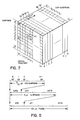
- Figs. 3 and 4 illustrate a columnar or one-dimensional frame structure
- Fig. 5 a plurality of these are multiplexed together and illustrated by a square or two-dimensional frame structure, so a plurality of these may be multiplexed together and illustrated by a cubic or three-dimensional frame structure.
- Fig. 8 shows the same multiplex frame as Fig. 7, in an alternative form.
- An arrow A1 indicates the sequence of multiplexing words from these N frames, one word from each of the N frames being interleaved on a word-by-word basis in a respective sub-subframe.
- An arrow A2 on a front face of the cubic structure illustrates the sequence of multiplexing the sub-subframes together, this corresponding to the arrow A in Fig. 5.
- each sub-subframe consists of interleaved words, one from each of the N frames, or planes in Fig. 7.
- Fig. 8 also shows the duration of the frame, subframes, and sub-subframes, respectively 125us, 5us, and 5/32us.
- N 32 and 10 bits per word, the bit rate of the multiplexed frame becomes 2.048Gb/s, a harmonic of the 64Mb/s bit rate for the frame of Fig. 5.
- the initial multiplexing of words in sub-subframe 0 of subframe 0 of each frame results in interleaving of the synchronizing words S0 of the N planes.
- this first synchronizing word is made different from the outer synchronizing words in this sub-subframe, and accordingly is designated S0' in Figs. 7 and 8.
- DS-0 (64kbps) channels can be mapped into, and hence transmitted as, channels within any virtual tributary, either individually to provide 64kbps services or collectively to provide services at integral multiples of this bit rate.
- conventional DS-1 channels can be mapped into synchronous DS-1 channels, or complete virtual tributaries.
- DS-1C (3.152Mb/s), DS-2 (6.312Mb/s), and DS-3 (44.736Mb/s) channels can each be mapped into an appropriate number of virtual tributaries and transmitted asynchronously, or can be demultiplexed to DS-1 channels and transmitted accordingly.
- DS-3 channels in the Syntran format in which there are 672 time slots in each master frame, can be mapped into 28 of the 31 non-synchronizing virtual tributaries of a frame as shown in Fig. 5, leaving 3 virtual tributaries free to carry other traffic, transmitting 24 bytes and one frame word in each virtual tributary.
- a main advantage of the multiplex format becomes apparent: If a signal multiplexed for example as shown in Figs. 7 and 8 is sampled at a regular and periodic rate every 5/32us (the sub-subframe period), taking one word on each sample, this yields a signal in the multiplex format of Figs. 5 and 6; if the same signal multiplexed as shown in Figs. 7 and 8 is instead sampled at a regular and periodic rate every 5us (the subframe period), again taking one word on each sample, this yields a signal in the format of Fig. 4, i.e. a single virtual tributary or synchronous DS-1 signal; and if this same signal multiplexed as shown in Figs.
- a signal multiplexed in the format of Figs. 5 and 6 can be sampled at a regular and periodic rate every 5us (the subframe period) or 125us (the frame period), taking one word on each sample, to yield respectively one virtual tributary or one DS-0 channel.
- the multiplex formats described above enable individual channels at different levels (e.g. DS-0, synchronous DS-1) to be directly accessed in the multiplexed bit stream, in an easy and convenient manner as a result of their periodicity, without any need for demultiplexing and subsequent remultiplexing.
- the periodic nature of the individual channels facilitates their switching collectively in groups to provide services which have bandwidths which are arbitrary integral multiples of 64kb/s.
- the synchronizing channel CH.0 of the virtual tributary does not have to be aligned so that it occurs in subframe 0, but rather it can be allowed to occur in any of the subframes 0 to 24 for any individual virtual tributary. Alignment of the synchronizing channel CH.0 to occur in subframe 0, and hence knowledge of the relative positions of the DS-0 channels within the virtual tributary, only becomes necessary when the virtual tributary must be demultiplexed to the DS-0 level.
- Fig. 9 illustrates a virtual tributary having an arbitrary relationship of its channels CH.0 to CH.24 to the subframes 0 to 25 of a multiplexed signal which can include this virtual tributary in the manner shown in any of Figs. 5 to 8.
- each word of the virtual tributary is assumed in this case to have 10 bits, the tenth bit in each word being indicated as a parity bit P for the word, whereby each word can be checked individually for the integrity of its data.
- the synchronizing channel CH.0 is identified, in this example, by always having a 0 bit as the ninth bit of each word.
- Each of the other, information, channels CH.1 to CH.24 contains a bit B as the ninth bit, the bit B being 1 for each one of these channels at least some of the time. Initially it is assumed here that the bit B is 1 for each of the information channels CH.1 to CH.24 in each frame, whereby a single 0 in the ninth bit position of a word uniquely identifies the synchronizing channel CH.0.
- the conventional DS-1 bit stream shown in Fig. 1 is conveniently mapped into the virtual tributary shown in Fig. 9 in that the 8 bits from each of the channels CH.1 to CH.24 in Fig. 1 become the first eight bits 1-8 of the corresponding channels CH.1 to CH.24 in Fig. 9, and the framing bit in Fig. 1, whose binary value changes in accordance with a known framing pattern, can become one of the bits 1-8 of the synchronizing channel CH.0 in Fig. 9 to preserve this framing pattern.
- the other seven of the bits 1-8 of the synchronizing channel CH.0 can be used if desired for other purposes, such as for indicating bipolar violations, frame slips, alarm conditions, and signalling frames.
- the ninth bit of each word i.e. the bit B
- each bit B is variably 1 and 0, and hence is 1 at least some of the time.
- the ninth bit of the synchronizing channel CH.0 remains 0 in every frame, so that it can still be properly distinguished from the other bits B, within a few frames using known synchronizing techniques.
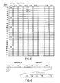
- Fig. 10 illustrates one manner in which the bit B, or ninth bit position, of an individual information channel can be conveniently used to transmit signalling and other service-related information.
- each bit B frame as shown in Fig. 10 has a frame period of 192x125us or 24ms.
- the bit B frame in Fig. 10 is illustrated for convenience as six columns of 32 bits, the six columns corresponding to the fact that a signalling bit can occur in every sixth frame.
- bits in adjacent columns and the same row occur 125us apart
- bits in the same column and adjacent rows occur 6x125us apart.
- the overall bandwidth provided for each 64kbps service by the bits B is 1 bit every 125us frame, or 8kbps.
- bits F0, F1, and F2 identify the bit B framing structure, and correspondingly the signalling frame structure.
- the bit F0 is 0 representing the start of a bit B frame
- each bit F1 is 1, and the bits F2 can be 0 or can define a pattern of 1's and 0's.
- the sixth column in Fig. 10 corresponds to the signalling frames and the bit B is used to represent the A, B, C, and D signalling bits.
- the second and third columns in Fig. 10 indicate that the bit B in the respective frames can be used to represent 32-bit source and destination addresses respectively, identifying unique addresses for stations respectively originating and terminating a connection. These addresses facilitate end-to-end checking of the connection.
- the bits in columns four and five in Fig. 10 provide for 6 CRC (cyclic redundancy code) check bits, which can be used to carry a CRC for the previous bit B frame (on the same service or channel) for checking the integrity of data; two format bits FM1 and FM2 which constitute a 2-bit code (for example 00) representing the format shown in Fig. 10, which can be changed to represent different formats; and 56 overhead information bits.
- the overhead information bits can be used for service control and/or verification, for example for requesting and confirming a minimum error rate and maximum delay for the service, indicating failures, and so on.
- the ninth or B bit may be used for each service or 64kbps channel to provide service-related overhead information, and many other ways of transmitting this information using such a bit can be devised.
- an overhead information packet structure may instead be assigned to the information in this ninth bit position.
- this bit may be dispensed with and the integrity of the data can be checked using parity over a much larger, or using a CRC check over a very much larger, block of information, and transmitting the parity or CRC check bits in the service-related overhead information in the ninth or B bit.
- the B bit will in these cases be variably 1 and 0, so that the B bits of the information channels CH.1 to CH.24 are distinguishable from the ninth bit of the synchronizing channel CH.0 which is always 0 (in this example), whereby for each virtual tributary the synchronizing channel CH.0 can be identified regardless of its position relative to the frame structure of Figs. 5 to 8.
- the synchronizing channel CH.0 can alternatively be identified in known manner by providing in this channel a predetermined word or bit sequence, which is detected with a degree of confidence that this is in fact the synchronizing channel being built up over a plurality of frames using a so-called confidence register.
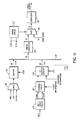
- FIG. 11 illustrates a circuit arrangement which may be used for producing a multiplexed bit stream having multiplex frames of the form described above.
- FIG. 11 there is illustrated a 10-bit wide data bus 20 to which 10-bit wide words of the virtual tributaries VT0 to VT31 are supplied cyclically in turn under the control of strobe signals ST0 to ST31 respectively supplied by a timing circuit 22.
- circuitry is shown only for the virtual tributaries VT0 and VT1, circuitry for each of the tributaries VT2 to VT31 being similar to that for the tributary VT1.
- the circuitry for this tributary includes a DS-1 input circuit 24, a framing circuit 26, and a virtual tributary output circuit 28.
- the input circuit 24 the DS-1 bit stream is converted from a bipolar signal into a unipolar signal and the 1.544MHz clock signal is recovered, the data and clock signals being supplied to the framing circuit 26.
- the framing circuit 26 the DS-1 frame timing is determined and the framing bit F (Fig. 1) is stuffed with an additional 7 bits to form the 8 bits of the synchronizing channel CH.0 (Fig. 2), so that the bit rate is increased from 1.544MHz to 1.6MHz.
- this serial data is converted to 8-bit parallel form by a serial-to-parallel converter, the overhead information is supplied as the ninth bit, and a parity bit is determined and added as a tenth bit, to produce a virtual tributary of the form shown in Fig. 9.
- the virtual tributary VT0 is produced by multiplexing together the signals of this tributary, for example network data link signals (NDL), CRC signals (CRC), and other desired signals (OTHER), in a multiplexer 30 and buffering these in a buffer 32 whose output is controlled by the strobe signal ST0.
- NDL network data link signals
- CRC CRC signals
- OTHER desired signals
- the strobe signals ST0 to ST31 are phased to supply the words of the tributaries VT0 to VT31 in turn, word-interleaved, to the bus 20.
- the 10-bit words from the bus 20 are converted into 12-bit words for transmission by a 10B12B converter 34 in accordance with a desired line coding scheme.
- the synchronizing word S0 is inserted in the resulting 12-bit wide stream at the start of each multiplex frame.
- the synchronizing words S1 to S4 can be similarly provided in the word stream at appropriate times under the control of the timing circuit 22. In this manner each synchronizing word can be selected to be a clearly identifiable 12-bit word which does not occur in a normal data stream, thereby facilitating the subsequent recovery of synchronizing information.
- the synchronizing words S0 to S4 may be supplied to the multiplexer 30 for incorporation in the tributary VT0 information; this procedure in particular may be used in the event that only the 10-bit data is transmitted without any line coding, the converter 34 and multiplexer 36 in this case being dispensed with.
- the parallel data is subsequently converted to serial data by a serializer 38, from which it is forwarded as a serial output bit stream.
Landscapes
- Engineering & Computer Science (AREA)
- Computer Networks & Wireless Communication (AREA)
- Signal Processing (AREA)
- Time-Division Multiplex Systems (AREA)
- Use Of Switch Circuits For Exchanges And Methods Of Control Of Multiplex Exchanges (AREA)
Priority Applications (1)
| Application Number | Priority Date | Filing Date | Title |
|---|---|---|---|
| AT86308297T ATE91363T1 (de) | 1985-11-01 | 1986-10-24 | Multiplexverfahren fuer digitale signale. |
Applications Claiming Priority (2)
| Application Number | Priority Date | Filing Date | Title |
|---|---|---|---|
| CA000494466A CA1252234A (fr) | 1985-11-01 | 1985-11-01 | Methode de multiplexage de signaux numeriques |
| CA494466 | 1985-11-01 |
Publications (3)
| Publication Number | Publication Date |
|---|---|
| EP0222544A2 true EP0222544A2 (fr) | 1987-05-20 |
| EP0222544A3 EP0222544A3 (en) | 1988-10-26 |
| EP0222544B1 EP0222544B1 (fr) | 1993-07-07 |
Family
ID=4131788
Family Applications (1)
| Application Number | Title | Priority Date | Filing Date |
|---|---|---|---|
| EP86308297A Expired - Lifetime EP0222544B1 (fr) | 1985-11-01 | 1986-10-24 | Méthode de multiplexage de signaux numériques |
Country Status (6)
| Country | Link |
|---|---|
| US (1) | US4764921A (fr) |
| EP (1) | EP0222544B1 (fr) |
| JP (2) | JPS62155697A (fr) |
| AT (1) | ATE91363T1 (fr) |
| CA (1) | CA1252234A (fr) |
| DE (1) | DE3688673T2 (fr) |
Cited By (8)
| Publication number | Priority date | Publication date | Assignee | Title |
|---|---|---|---|---|
| US4981371A (en) * | 1989-02-17 | 1991-01-01 | Itt Corporation | Integrated I/O interface for communication terminal |
| WO1993014582A1 (fr) * | 1992-01-15 | 1993-07-22 | Siemens Aktiengesellschaft | Procede de commutation de signaux numeriques |
| EP0622919A1 (fr) * | 1993-04-30 | 1994-11-02 | Alcatel N.V. | Dispositif d'interface pour conversion de format |
| EP0642242A2 (fr) * | 1993-09-08 | 1995-03-08 | Alcatel Mobile Communication France | Trame de transmission de données à ambiguité réduite, émetteur et récepteur adaptés à une telle trame |
| FR2709901A1 (fr) * | 1993-09-08 | 1995-03-17 | Alcatel Mobile Comm France | Trame de transmission à ambiguité réduite, émetteur et récepteur adptés à une telle trame. |
| WO1998029976A1 (fr) * | 1996-12-26 | 1998-07-09 | Northern Telecom Limited | Procede et systeme de transfert de donnees en serie |
| DE19802365C2 (de) * | 1998-01-22 | 2002-06-13 | Siemens Ag | Übertragungsverfahren und Übertragungssystem |
| DE4227736B4 (de) * | 1992-08-21 | 2004-11-25 | Philips Intellectual Property & Standards Gmbh | Netzwerk mit einer Abzweig- und Kanalverteilungsvorrichtung |
Families Citing this family (25)
| Publication number | Priority date | Publication date | Assignee | Title |
|---|---|---|---|---|
| WO1988001815A1 (fr) * | 1986-08-30 | 1988-03-10 | Fujitsu Limited | Dispositif diviseur multiplex dans un systeme de multiplexage synchrone |
| US4928276A (en) * | 1986-09-02 | 1990-05-22 | Ag Communication Systems Corporation | T1 line format for robbed signaling for use with CCITT 32K bit per second ADPCM clear channel transmission and 64KBPS clear channel transmission |
| US4916693A (en) * | 1987-05-15 | 1990-04-10 | Mitsubishi Denki Kabushiki Kaisha | Digital time division multiplex system and method of controlling same |
| US4893306A (en) * | 1987-11-10 | 1990-01-09 | Bell Communications Research, Inc. | Method and apparatus for multiplexing circuit and packet traffic |
| JP2760797B2 (ja) * | 1988-03-18 | 1998-06-04 | 株式会社日立製作所 | ディジタル信号の多重化方法 |
| US4930125A (en) * | 1989-01-30 | 1990-05-29 | General Datacom, Inc. | Multiplexer frame synchronization technique |
| US5060229A (en) * | 1989-05-12 | 1991-10-22 | Alcatel Na Network Systems Corp. | Serial transport frame format method |
| US6125111A (en) * | 1996-09-27 | 2000-09-26 | Nortel Networks Corporation | Architecture for a modular communications switching system |
| UA53669C2 (uk) * | 1996-11-18 | 2003-02-17 | Сіменс Акцієнгезельшафт | Спосіб та система базової станції для конфігурування радіоінтерфейсу між мобільною станцією та базовою станцією мобільної радіосистеми пакетної передачі даних з часовим мультиплексуванням |
| US6782066B1 (en) * | 1998-06-16 | 2004-08-24 | 3Com Corporation | Method and system for detecting frame slips in a digital communications channel |
| US6195385B1 (en) * | 1998-06-30 | 2001-02-27 | Cisco Systems, Inc. | HTU-C clocking from a single source |
| US7295554B1 (en) * | 1999-03-12 | 2007-11-13 | Lucent Technologies Inc. | Word Multiplexing of encoded signals into a higher bit rate serial data stream |
| DE60037957T2 (de) * | 1999-09-17 | 2009-01-29 | Nippon Telegraph And Telephone Corp. | Transportsystem und -verfahren |
| JP3522619B2 (ja) | 2000-01-05 | 2004-04-26 | 株式会社エヌ・ティ・ティ・ドコモ | マルチキャリアcdma伝送システムにおける送信機 |
| US20030103533A1 (en) * | 2000-02-04 | 2003-06-05 | Wolfgang Hilgers | Parallel signal dividing and signal processing in multiplex devices with a high ordinal number |
| US7352758B2 (en) * | 2000-02-18 | 2008-04-01 | Tellabs Operations, Inc. | Dynamic bandwidth management using signaling protocol and virtual concatenation |
| ATE422746T1 (de) * | 2000-06-14 | 2009-02-15 | Vitesse Semiconductor Corp | Transparent-transport-overhead-abbildung |
| US7221684B1 (en) * | 2002-01-08 | 2007-05-22 | Cisco Technology, Inc. | Increasing network efficiency using packet compression and decompression |
| JP3947417B2 (ja) * | 2002-03-20 | 2007-07-18 | 富士通株式会社 | 波長分割多重システム |
| US7408939B1 (en) | 2003-09-09 | 2008-08-05 | Ceterus Networks, Inc. | Method and apparatus for transport of fractional datastreams over frame-based transport systems |
| US7451381B2 (en) * | 2004-02-03 | 2008-11-11 | Phonex Broadband Corporation | Reliable method and system for efficiently transporting dynamic data across a network |
| US8094767B1 (en) | 2005-12-12 | 2012-01-10 | Exalt Communications Inc. | Method and apparatus for timing and/or frequency synchronization in an RF receiver |
| US8295304B1 (en) * | 2007-12-27 | 2012-10-23 | Exalt Communications Incorporated | Adaptive multi-service data framing |
| US8428186B1 (en) | 2007-12-27 | 2013-04-23 | Exalt Communications Incorporated | Decision directed DC offset removal |
| US8611356B2 (en) | 2009-11-13 | 2013-12-17 | Exalt Communications Incorporated | Apparatus for ethernet traffic aggregation of radio links |
Citations (2)
| Publication number | Priority date | Publication date | Assignee | Title |
|---|---|---|---|---|
| JPS54146517A (en) | 1978-05-09 | 1979-11-15 | Fujitsu Ltd | Digital multiplication transmission system |
| EP0053230A1 (fr) | 1980-11-27 | 1982-06-09 | ANT Nachrichtentechnik GmbH | Système numérique de transmission d'information |
Family Cites Families (9)
| Publication number | Priority date | Publication date | Assignee | Title |
|---|---|---|---|---|
| JPS5744264B2 (fr) * | 1975-01-24 | 1982-09-20 | ||
| US3995119A (en) * | 1975-05-30 | 1976-11-30 | Gte Automatic Electric Laboratories Incorporated | Digital time-division multiplexing system |
| JPS5434606A (en) * | 1977-08-22 | 1979-03-14 | Nec Corp | Digital channel device |
| JPS5434607A (en) * | 1977-08-22 | 1979-03-14 | Nec Corp | Multiple channel device |
| US4143246A (en) * | 1977-09-06 | 1979-03-06 | Bell Telephone Laboratories, Incorporated | Time division line interface circuit |
| JPS5654193A (en) * | 1979-10-11 | 1981-05-14 | Nec Corp | Digital exchange system |
| US4507779A (en) * | 1981-05-19 | 1985-03-26 | Ibm Corporation | Medium speed multiples data |
| GB2143405B (en) * | 1983-07-13 | 1986-08-13 | Standard Telephones Cables Ltd | Time division multiplex system |
| US4607364A (en) * | 1983-11-08 | 1986-08-19 | Jeffrey Neumann | Multimode data communication system |
-
1985
- 1985-11-01 CA CA000494466A patent/CA1252234A/fr not_active Expired
- 1985-11-12 US US06/797,264 patent/US4764921A/en not_active Expired - Lifetime
-
1986
- 1986-10-24 DE DE86308297T patent/DE3688673T2/de not_active Expired - Lifetime
- 1986-10-24 AT AT86308297T patent/ATE91363T1/de not_active IP Right Cessation
- 1986-10-24 EP EP86308297A patent/EP0222544B1/fr not_active Expired - Lifetime
- 1986-10-31 JP JP61258700A patent/JPS62155697A/ja active Pending
- 1986-10-31 JP JP61258699A patent/JPH0720090B2/ja not_active Expired - Lifetime
Patent Citations (2)
| Publication number | Priority date | Publication date | Assignee | Title |
|---|---|---|---|---|
| JPS54146517A (en) | 1978-05-09 | 1979-11-15 | Fujitsu Ltd | Digital multiplication transmission system |
| EP0053230A1 (fr) | 1980-11-27 | 1982-06-09 | ANT Nachrichtentechnik GmbH | Système numérique de transmission d'information |
Cited By (15)
| Publication number | Priority date | Publication date | Assignee | Title |
|---|---|---|---|---|
| US4981371A (en) * | 1989-02-17 | 1991-01-01 | Itt Corporation | Integrated I/O interface for communication terminal |
| WO1993014582A1 (fr) * | 1992-01-15 | 1993-07-22 | Siemens Aktiengesellschaft | Procede de commutation de signaux numeriques |
| US5579310A (en) * | 1992-01-15 | 1996-11-26 | Siemens Aktiengesellschaft | Method for switching through digital signals |
| DE4227736B4 (de) * | 1992-08-21 | 2004-11-25 | Philips Intellectual Property & Standards Gmbh | Netzwerk mit einer Abzweig- und Kanalverteilungsvorrichtung |
| EP0622919A1 (fr) * | 1993-04-30 | 1994-11-02 | Alcatel N.V. | Dispositif d'interface pour conversion de format |
| US5592653A (en) * | 1993-04-30 | 1997-01-07 | Alcatel, N.V. | Interface conversion device |
| EP0642242A3 (fr) * | 1993-09-08 | 1995-05-10 | Alcatel Mobile Comm France | Trame de transmission de données à ambiguité réduite, émetteur et récepteur adaptés à une telle trame. |
| FR2709901A1 (fr) * | 1993-09-08 | 1995-03-17 | Alcatel Mobile Comm France | Trame de transmission à ambiguité réduite, émetteur et récepteur adptés à une telle trame. |
| FR2709896A1 (fr) * | 1993-09-08 | 1995-03-17 | Alcatel Mobile Comm France | Trame de transmission de données à ambiguïté réduite, émetteur et récepteur adaptés à une telle trame. |
| US5875062A (en) * | 1993-09-08 | 1999-02-23 | Alcatel Mobile Communication France | Transmitter, receiver and frame for transmitting data with reduced ambiguity |
| EP0642242A2 (fr) * | 1993-09-08 | 1995-03-08 | Alcatel Mobile Communication France | Trame de transmission de données à ambiguité réduite, émetteur et récepteur adaptés à une telle trame |
| WO1998029976A1 (fr) * | 1996-12-26 | 1998-07-09 | Northern Telecom Limited | Procede et systeme de transfert de donnees en serie |
| US5842007A (en) * | 1996-12-26 | 1998-11-24 | Northern Telecom Limited | Method and system for transferring high level control messaging framing and payload data in a serial stream in a communications system |
| US6061784A (en) * | 1996-12-26 | 2000-05-09 | Nortel Networks Corporation | Method and device for transferring data frames within a serial stream |
| DE19802365C2 (de) * | 1998-01-22 | 2002-06-13 | Siemens Ag | Übertragungsverfahren und Übertragungssystem |
Also Published As
| Publication number | Publication date |
|---|---|
| EP0222544A3 (en) | 1988-10-26 |
| JPH0720090B2 (ja) | 1995-03-06 |
| JPS62155635A (ja) | 1987-07-10 |
| DE3688673D1 (de) | 1993-08-12 |
| DE3688673T2 (de) | 1993-10-14 |
| US4764921A (en) | 1988-08-16 |
| JPS62155697A (ja) | 1987-07-10 |
| CA1252234A (fr) | 1989-04-04 |
| ATE91363T1 (de) | 1993-07-15 |
| EP0222544B1 (fr) | 1993-07-07 |
Similar Documents
| Publication | Publication Date | Title |
|---|---|---|
| EP0222544B1 (fr) | Méthode de multiplexage de signaux numériques | |
| EP0216456B1 (fr) | Structure de multiplexage | |
| US4520480A (en) | Digital transmission system | |
| AU656794B2 (en) | Virtual tributary path idle insertion using timeslot interchange | |
| WO1990006645A1 (fr) | Systeme de connexion croisee de signaux numeriques a haute vitesse | |
| JPH04211534A (ja) | データ伝送方法 | |
| US4581737A (en) | Bit compression multiplexing | |
| US4535451A (en) | Fourth-order digital multiplex system for transmitting a plurality of digital signals at a nominal bit rate of 44 736 kbit/s | |
| US7782812B2 (en) | System and method for multiplexing PDH and packet data | |
| JP3366330B2 (ja) | 時間又は空間ドメインにおいて切換を実行する方法 | |
| EP0341891B1 (fr) | Système de transmission de données à multiplex temporel | |
| US4697264A (en) | Bit compression multiplexing | |
| GB2187066A (en) | Time division multiplexed signalling | |
| AU671631B2 (en) | Method for transferring ancillary information in a basic time-division multiplex system | |
| US6621830B1 (en) | Variable rate subscriber bus | |
| JP2575348B2 (ja) | ビツト圧縮多重化システム | |
| US5892771A (en) | System for establishing a TDM information protocol over a communications path | |
| EP0220808A3 (fr) | Multiplexeur pour signaux numériques | |
| FI87125B (fi) | Foerfarande foer kodning av en linjesignal. | |
| GB2204764A (en) | Time division multiplex data system | |
| Simmonds et al. | Time division multiplexing | |
| JPH0785548B2 (ja) | 多重化方式 |
Legal Events
| Date | Code | Title | Description |
|---|---|---|---|
| PUAI | Public reference made under article 153(3) epc to a published international application that has entered the european phase |
Free format text: ORIGINAL CODE: 0009012 |
|
| AK | Designated contracting states |
Kind code of ref document: A2 Designated state(s): AT DE FR GB NL SE |
|
| PUAL | Search report despatched |
Free format text: ORIGINAL CODE: 0009013 |
|
| AK | Designated contracting states |
Kind code of ref document: A3 Designated state(s): AT DE FR GB NL SE |
|
| 17P | Request for examination filed |
Effective date: 19890425 |
|
| 17Q | First examination report despatched |
Effective date: 19910426 |
|
| RAP1 | Party data changed (applicant data changed or rights of an application transferred) |
Owner name: NORTHERN TELECOM LIMITED |
|
| GRAA | (expected) grant |
Free format text: ORIGINAL CODE: 0009210 |
|
| AK | Designated contracting states |
Kind code of ref document: B1 Designated state(s): AT DE FR GB NL SE |
|
| PG25 | Lapsed in a contracting state [announced via postgrant information from national office to epo] |
Ref country code: AT Effective date: 19930707 Ref country code: SE Effective date: 19930707 Ref country code: NL Effective date: 19930707 |
|
| REF | Corresponds to: |
Ref document number: 91363 Country of ref document: AT Date of ref document: 19930715 Kind code of ref document: T |
|
| REF | Corresponds to: |
Ref document number: 3688673 Country of ref document: DE Date of ref document: 19930812 |
|
| ET | Fr: translation filed | ||
| NLV1 | Nl: lapsed or annulled due to failure to fulfill the requirements of art. 29p and 29m of the patents act | ||
| PLBE | No opposition filed within time limit |
Free format text: ORIGINAL CODE: 0009261 |
|
| STAA | Information on the status of an ep patent application or granted ep patent |
Free format text: STATUS: NO OPPOSITION FILED WITHIN TIME LIMIT |
|
| 26N | No opposition filed | ||
| REG | Reference to a national code |
Ref country code: GB Ref legal event code: IF02 |
|
| REG | Reference to a national code |
Ref country code: FR Ref legal event code: CD |
|
| PGFP | Annual fee paid to national office [announced via postgrant information from national office to epo] |
Ref country code: GB Payment date: 20050914 Year of fee payment: 20 |
|
| PGFP | Annual fee paid to national office [announced via postgrant information from national office to epo] |
Ref country code: FR Payment date: 20051006 Year of fee payment: 20 |
|
| PGFP | Annual fee paid to national office [announced via postgrant information from national office to epo] |
Ref country code: DE Payment date: 20051031 Year of fee payment: 20 |
|
| PG25 | Lapsed in a contracting state [announced via postgrant information from national office to epo] |
Ref country code: GB Free format text: LAPSE BECAUSE OF EXPIRATION OF PROTECTION Effective date: 20061023 |
|
| REG | Reference to a national code |
Ref country code: GB Ref legal event code: PE20 |