EP0222108B1 - Transmission hydromécanique continue avec dérivation de puissance, notamment pour véhicules automobiles - Google Patents
Transmission hydromécanique continue avec dérivation de puissance, notamment pour véhicules automobiles Download PDFInfo
- Publication number
- EP0222108B1 EP0222108B1 EP86112723A EP86112723A EP0222108B1 EP 0222108 B1 EP0222108 B1 EP 0222108B1 EP 86112723 A EP86112723 A EP 86112723A EP 86112723 A EP86112723 A EP 86112723A EP 0222108 B1 EP0222108 B1 EP 0222108B1
- Authority
- EP
- European Patent Office
- Prior art keywords
- planetary gear
- compounding
- shaft
- power
- unit
- Prior art date
- Legal status (The legal status is an assumption and is not a legal conclusion. Google has not performed a legal analysis and makes no representation as to the accuracy of the status listed.)
- Expired - Lifetime
Links
Images


Classifications
-
- F—MECHANICAL ENGINEERING; LIGHTING; HEATING; WEAPONS; BLASTING
- F16—ENGINEERING ELEMENTS AND UNITS; GENERAL MEASURES FOR PRODUCING AND MAINTAINING EFFECTIVE FUNCTIONING OF MACHINES OR INSTALLATIONS; THERMAL INSULATION IN GENERAL
- F16H—GEARING
- F16H47/00—Combinations of mechanical gearing with fluid clutches or fluid gearing
- F16H47/02—Combinations of mechanical gearing with fluid clutches or fluid gearing the fluid gearing being of the volumetric type
- F16H47/04—Combinations of mechanical gearing with fluid clutches or fluid gearing the fluid gearing being of the volumetric type the mechanical gearing being of the type with members having orbital motion
-
- F—MECHANICAL ENGINEERING; LIGHTING; HEATING; WEAPONS; BLASTING
- F16—ENGINEERING ELEMENTS AND UNITS; GENERAL MEASURES FOR PRODUCING AND MAINTAINING EFFECTIVE FUNCTIONING OF MACHINES OR INSTALLATIONS; THERMAL INSULATION IN GENERAL
- F16H—GEARING
- F16H37/00—Combinations of mechanical gearings, not provided for in groups F16H1/00 - F16H35/00
- F16H37/02—Combinations of mechanical gearings, not provided for in groups F16H1/00 - F16H35/00 comprising essentially only toothed or friction gearings
- F16H37/06—Combinations of mechanical gearings, not provided for in groups F16H1/00 - F16H35/00 comprising essentially only toothed or friction gearings with a plurality of driving or driven shafts; with arrangements for dividing torque between two or more intermediate shafts
- F16H37/08—Combinations of mechanical gearings, not provided for in groups F16H1/00 - F16H35/00 comprising essentially only toothed or friction gearings with a plurality of driving or driven shafts; with arrangements for dividing torque between two or more intermediate shafts with differential gearing
- F16H37/0833—Combinations of mechanical gearings, not provided for in groups F16H1/00 - F16H35/00 comprising essentially only toothed or friction gearings with a plurality of driving or driven shafts; with arrangements for dividing torque between two or more intermediate shafts with differential gearing with arrangements for dividing torque between two or more intermediate shafts, i.e. with two or more internal power paths
- F16H37/084—Combinations of mechanical gearings, not provided for in groups F16H1/00 - F16H35/00 comprising essentially only toothed or friction gearings with a plurality of driving or driven shafts; with arrangements for dividing torque between two or more intermediate shafts with differential gearing with arrangements for dividing torque between two or more intermediate shafts, i.e. with two or more internal power paths at least one power path being a continuously variable transmission, i.e. CVT
- F16H2037/088—Power split variators with summing differentials, with the input of the CVT connected or connectable to the input shaft
- F16H2037/0886—Power split variators with summing differentials, with the input of the CVT connected or connectable to the input shaft with switching means, e.g. to change ranges
Definitions
- the invention relates to a continuously variable hydrostatic-mechanical branching transmission for motor vehicles according to the preamble of claim 1.
- a hydrostatic-mechanical transmission with power split and with a four-shaft summation planetary transmission is known from EP-A 081 696.
- the object of the invention is to improve the known transmission, in particular to provide a continuously variable hydrostatic-mechanical branching transmission which reduces the specific requirements for the hydrostats to a minimum, i.e. that reduces the hydrostatic power share and brings the noise, efficiency and service life-determining parameters, such as hydrostatic pressure, hydrostatic speeds and the size of these components and their arrangement to an acceptable and technically feasible level.
- the speed level should be such that an adaptation on the output side by additional gear ratios is unnecessary.
- a high level of economy should also be achieved through risk-free, rational production.
- an assembly and service-friendly modular construction should be feasible and compact, vehicle-friendly overall constructions should be possible.
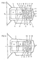
- a combination of a first summing planetary gear 4 (FIG. 1) with a second summing planetary gear (5) ensures that the speed of a second hydrostatic unit B in the starting area of the vehicle is in the same direction (FIG. 2, 3) with the drive speed.
- the two summation planetary gears 4, 5 have opposite directions of rotation at the end of the first shift range.
- the speed of the hydrostatic unit B is returned until the speed of a drive shaft 2 is reached.
- all elements of the first summation planetary gear 4 as well as both hydrostatic units A, B and the drive shaft 2 rotate in the same direction at the same speed, ie in synchronous operation.
- the translation of the drive shaft to the output shaft is 1. If the second hydrostatic unit B is designed as an adjustment unit, the number of outputs can be increased further by secondary adjustment, which is advantageous for many applications in order to create an additional overdrive range.
- the speed of the output shaft 3 is still relatively low here, so that the usual translations of the motor vehicles can be used.
- the reverse range can be realized without an additional clutch or other transmission elements.
- the construction of the gearbox is relatively simple. All components can be manufactured using conventional manufacturing methods, and the assemblies, the summation planetary gear 4, 5 and the clutch pack can be combined in a simple manner to form a unit or assembly unit.
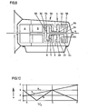
- the ratios (Fig. 3) in the two summation planetary gears 4, 5 are designed so that the hydrostatic unit A is not yet swung out to its maximum end position at the starting point, but to about 60% of its maximum adjustment. When the hydrostatic unit A is swiveled out to the maximum final adjustment from this point, the output shaft receives 3 negative speeds for the reversing speed. In this embodiment, no secondary adjustment is required.
- a brake 10 a serves to hold the web 17 a as the first range circuit.
- the drive shaft 2 is connected directly to the web 21 of the planetary stage of the second summation planetary gear 5, which consists of a ring gear 19 and a sun gear 20.
- the clutch 11 including the drive shaft 2 and both hydrostatic units A, B rotate. Due to the omission of the relative speeds in this area, the rolling power and thus the transmission efficiency are also very favorable.
- the rolling and power loss can be kept low due to the generally low relative speeds in the second range, which has an operating share of over 80% when used on a car. This makes it particularly useful to use the secondary control of the hydrostatic transmission A, B (see speed line Bs) in favor of a large overdrive range (FIG. 2), especially since the reverse drive range can also be implemented very inexpensively at the same time.
- FIG. 4 differs from that according to FIG. 1 in that an additional clutch 12 is provided for the reverse driving range.
- a direct connection is created here via the two ring gears of the summation planetary gear 4 to the second hydrostatic unit B, as a result of which a purely hydrostatic transmission in the reverse driving range is established with the clutch 12 closed.
- the full adjustment range of the hydrostatic transmission in the first shift range can be used in favor of a higher power capacity compared to the exemplary embodiment according to the speed plan in FIG. 3, in which the reverse drive range is also integrated in the first shift range (FIG. 5).
- An exemplary embodiment according to FIG. 6 has a separate reverse shifting range due to the addition of a further planetary gear 28 and a clutch 27 or brake 22.
- a large reverse driving range is possible, as is generally the case in cars.
- This combination of gears is particularly useful when used in commercial vehicles or buses, or in machines.
- the translation in the second summing planetary gear 5 is adapted according to the desired spreading range, which causes the second hydrostatic unit B to be driven at a speed which is higher than that of the first hydrostatic unit A in the starting state via the summing planetary gear.
- the start-up control is achieved in that the bypass valve 55 receives a signal 36, which can either be a speed signal and / or a signal from the brake actuation or / and a load signal.
- the speed spread of the hydrostatic unit B is represented by a broken line 37.
- the maximum speed ratio of hydrostatic unit B to hydrostatic unit A is 1: 2.
- the function of the bypass valve 55 replaces the function of a starting clutch, as is known in another, complex transmission of this type.
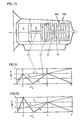
- FIG. 9 Another exemplary embodiment of a transmission with three forward shift ranges is described with reference to FIG. 9, the reverse range being integrated in the first shift range (as can be seen from the associated speed plan in FIG. 10).
- the basic building blocks are largely identical to the previously described versions.
- the main difference lies in the fact that the first summation planetary gear 30 is expanded by a further planetary gear set consisting of a ring gear 31, a web 32 and a sun gear 33.
- the fourth shaft here forms the sun gear 33, which is connected to the output shaft 3 via a further clutch 35 when the third driving range is shifted.
- the reverse range is also integrated in the first shifting range, as shown in the associated speed plan (FIG.
- the third area can be realized here by a relatively low cost, whereby the torque conversion area is doubled, ie the performance of the entire transmission is doubled.
- the output speed increases in this embodiment by twice the input speed.
- an overdrive range of approximately twice the translation range should be selected.
- This transmission design while maintaining the usual axle ratio, offers ideal conditions in order to be able to fully exploit the offered potential for saving fuel, for example in the car sector.
- This transmission design is therefore characterized by a very large converter range and thus a sufficient overdrive range with very small hydrostatic units, which ensures the additional advantage of a particularly favorable transmission efficiency and low specific load on the hydrostatic units.
- This embodiment also counteracts the noise problems.
- the transmission design described can be expanded according to a further exemplary embodiment according to FIG. 11 by an additional clutch for the reverse range, which is switched purely hyrdostatically as in the embodiment according to FIG. 4 via clutch 12.
- the first driving range with speed spread of the second hydrostatic unit B can be carried out similarly to the exemplary embodiment according to FIG. 6 and according to the speed plan according to FIG. 7 in favor of an even larger conversion range in accordance with the high passenger car performance classes or also when used in commercial vehicles, buses or work machines (FIG. 17, 18).
- a further exemplary embodiment according to FIG. 13 corresponds to particularly high demands both in terms of the power capacity, the driving performance and the overall driving comfort.
- This offers three forward driving ranges and a separate power-split reverse driving range, the size of which can be arbitrarily adjusted by adapting a further planetary gear set and the range switching via a brake 22a can be adjusted.
- the first driving range can also be carried out with a range spread in favor of a large conversion range, which also applies to the reverse range.
- the size of the reversing speed can be adapted to the requirements by adapting the ratio of a planetary gear 28a, which is also evident from the associated speed plans (14, 15).
- a further exemplary embodiment according to FIG. 16 is identical in terms of its basic structural units to the exemplary embodiment according to FIG. 6. It differs only in the arrangement of the hydrostatic units A, B, which here are the components of the branching gear units, i.e. the summation planetary gears 4, 5, the planetary gear 28 and the clutch 9 are arranged offset, in particular with regard to installation conditions, such as are required in commercial vehicles, buses or work machines.
- the drive motor can be connected at various points.
- drive shafts 40, 42 and the drive connection 43 are available, which is particularly advantageous given the diverse installation conditions of the motor vehicles.
- FIG. 17 corresponds essentially to the installation conditions of gravity vehicles, such as buses, commercial vehicles, work machines and in particular tractors, and has three forward driving ranges and a separate reverse driving range with power split.
- This embodiment has particular advantages in terms of fuel savings, environmental friendliness and driving comfort, particularly for use in buses.
- the third area can be used almost entirely as an overdrive area for fuel savings.
- a further exemplary embodiment offers three forward driving ranges and three reverse driving ranges, the total reverse speed of the reversing range being able to be adapted as desired by means of an additional planetary gear 44.
- This embodiment is particularly advantageous for work machines such as bulldozers or any tracked vehicles.
- the overall characteristic corresponds to the transmission design according to the exemplary embodiment according to FIG. 13, the entire forward driving range being reversed by the planetary reversing transmission 44 and a clutch / brake 45.
- this exemplary embodiment also offers the advantage of different connection options for the internal combustion engine.
- the branching gear has the advantage that all components are easy to manufacture and assemble, so that almost risk-free production is guaranteed.
- a modular construction can be implemented which is extremely easy to service.
- the individual assemblies namely the first summing planetary gear, the second summing planetary gear, the clutch pack and the additional elements for achieving the reversing speeds, can be combined to form individual assemblies.
- the individual assemblies can in turn be combined to form a main group, such as in the exemplary embodiments according to FIGS.
- the drive shaft 2 (FIG. 1), which is connected to the crankshaft of the drive motor without a clutch, drives the first hydrostatic unit A and the first shaft of the summation planetary gear 4 directly, the shaft being designed as a ring gear in this exemplary embodiment.
- the first hydrostatic unit A and the second hydrostatic unit B have the same speed and the same direction of rotation, which means that all elements of the summation planetary gear have 4 synchronous operation.
- a shaft of the first summation planetary gear 4 and the first shaft of the second summation planetary gear 5, both of which are designed as sun gears 8, 16, are in a driving connection with the second hydrostatic unit B.
- the hydrostatic power is accordingly divided between the two summation planetary gears 4, 5.
- the power added up in the first summing planetary gear 4 via the web 7 is transmitted in the first driving range to the sun gear 20 of the second summing planetary gear unit, with a partial power simultaneously flowing via the two ring gears 18, 19 of the second summing planetary gear 5, which corresponds to the total power of the sun gear 20 in the web 21 of the second summation planetary gear 5 additionally added, and which is forwarded together with the clutch 10 closed for the first driving range to the output shaft 3.
- the first hydrostatic unit A is adjusted to its full adjustment size. If the hydrostatic unit A is now adjusted to small adjustment values, the web 21 and thus the output shaft 3 begin to rotate.
- the functional sequence described within the first and second driving range is the same in the other exemplary embodiments.
- the changeover to the third driving range takes place with synchronous operation of all elements of the first summation planetary gear 30 with simultaneous synchronization of all elements of the two clutches 11 and 35 Drive through the negative adjustment range.
- the first hydrostatic unit A is set to a delivery volume "zero" by e.g. a mechanical spring centering, as is known in simple hydrostatic drives, is set in order to avoid engine starting resistances due to the flow resistances in the hydrostatic circuit, especially in the cold state.
- the oil pressure is used to close the area clutches and to supply the hydrostatic circuit, among other things. adapted to the respective load conditions, as is known per se, by load-dependent modulation e.g. about the high pressure of the hydrostatic transmission.
- Another advantage is that the speed of the gearbox can be adjusted to the respective operating conditions, e.g. thanks to an adjustable throttle valve for dosing the amount of oil in an adjusting cylinder via the high pressure of the hydrostatic transmission.
- the range shifts are almost seamless since they are carried out in synchronism with the coupling elements and, as is known per se, have a load overlap, with both clutches being closed for a short time.
- FIG. 19 Another exemplary embodiment of the branching transmission (FIG. 19) is distinguished by a particularly compact design.
- the area clutch 10 loaded with higher torque for the first forward travel area and the area clutch 27 also loaded with higher torque for the reverse travel area are arranged via the two less torque-loaded clutches 11, 35 of the second travel area and the third travel area. As a result, the entire clutch package can be made short.
- the reversible planetary gear 28 is arranged on the output side after the clutch pack, the ring gear 23 of which is connected to the web 21 of the second summation planetary gear unit 5 and a clutch member of the first range clutch 10.
- the web 25 of the reversing planetary gear stage 28 is fixed to the housing, and the sun gear 26 is connected to a link of the clutch 27 of the reverse driving range.
- the first summation planetary gear 130, 230, 330 can, as shown in FIGS. 20, 21, 22, be designed differently.
- the summation planetary gear 130 (FIG. 20) has two intermeshing first planet gears 131 and second planet gears 132, which are mounted together on a web 107.
- the first shaft of the summation planetary gear 130 is with the ring gear 106, which engages in first planet gears 131, the second shaft with the sun gear 108, which also engages in first planet gears 131, and the fourth shaft with the sun gear 133, which meshes with second planet gears 132 , connected.
- the third shaft forms the web for the planet gears 131, 312.
- the summation planetary gear (FIG. 21) consists of a first planetary stage with the sun gear 208, the planetary gears 213 and the ring gear 206 and a second planetary gear stage with the sun gear 210 made of intermeshing planet gears 211, 212 and the ring gear 207.
- the first shaft of the summation planetary gear 230 is connected to the ring gear 206 of the first planetary gear stage and the ring gear 207 of the second planetary gear stage.
- the second shaft with the sun gear 208 of the first planetary gear stage and the third shaft represent the web 209 for both planetary gear stages.
- the fourth shaft of the summation planetary gear is driven via the sun gear 210.
- the summation planetary gear 330 (FIG. 22) likewise consists of a first planetary gear stage with the sun gear 301, the land 302 and the ring gear 303 and a second planetary gear stage with the sun gear 304, the land 305 and the ring gear 306.
- the first shaft of the summation planetary gear 330 forms the web 302 of the first planetary gear stage
- the second shaft the ring gear 306 of the second planetary gear stage.
- the third shaft is connected to the ring gear 303 of the first planetary gear stage and the web 305 of the second planetary gear stage
- the fourth shaft of the summation planetary gear is connected to the sun gear 301 of the first planetary gear stage and to the sun gear 304 of the second planetary gear stage.
- the various designs of the summation planetary gear 130, 230, 330 are alternative solutions to the design of the summation planetary gear 30. Depending on the specific requirements when equipping different vehicles, there is a specific choice.
- the hydrostatic components are operated in an oil-free housing in order to improve the transmission efficiency.
- the feed and flush valves are - as is also known - designed so that the oil not required for leak oil compensation, which is used in particular for flushing and cooling the hydrostatic system, is not sprayed into the hydrostatic housing, but, if necessary, other consumers, such as Area couplings, lubrication devices, etc., supplied, and the rest can preferably be performed via the oil cooler.
- two shuttle valves arranged on both sides are preferably used, as they are known in principle as a feed valve for hydrostatics, one for the feed and the other valve releasing the low-pressure flow after the hydrostatic rinsing and cooling to the mentioned secondary consumers and possibly to the cooler .
- Both valves are - as is well known in the case of feed and flush valves - controlled by the respective high pressure, which closes the path to the high pressure side and at the same time opens the oil passage on both sides under low pressure.
- the first range clutch 10 or reverse range clutch 22; 22a; 27 are used as a starting clutch which, with the appropriate design, bridges the speed spread (FIG. 7, see line 37) and the first starting range up to translation point "X".
- the area clutch serving as a starting clutch can be activated with the same signals as the bypass valve 55.
Landscapes
- Engineering & Computer Science (AREA)
- General Engineering & Computer Science (AREA)
- Mechanical Engineering (AREA)
- Structure Of Transmissions (AREA)
Claims (26)
Applications Claiming Priority (4)
| Application Number | Priority Date | Filing Date | Title |
|---|---|---|---|
| DE3533191 | 1985-09-18 | ||
| DE3533191 | 1985-09-18 | ||
| DE3622045 | 1986-07-01 | ||
| DE19863622045 DE3622045A1 (de) | 1985-09-18 | 1986-07-01 | Stufenloses hydromechanisches verzweigungsgetriebe, insbesondere fuer kraftfahrzeuge |
Publications (3)
| Publication Number | Publication Date |
|---|---|
| EP0222108A2 EP0222108A2 (fr) | 1987-05-20 |
| EP0222108A3 EP0222108A3 (en) | 1987-08-26 |
| EP0222108B1 true EP0222108B1 (fr) | 1990-12-05 |
Family
ID=25836081
Family Applications (1)
| Application Number | Title | Priority Date | Filing Date |
|---|---|---|---|
| EP86112723A Expired - Lifetime EP0222108B1 (fr) | 1985-09-18 | 1986-09-15 | Transmission hydromécanique continue avec dérivation de puissance, notamment pour véhicules automobiles |
Country Status (2)
| Country | Link |
|---|---|
| EP (1) | EP0222108B1 (fr) |
| DE (1) | DE3622045A1 (fr) |
Families Citing this family (25)
| Publication number | Priority date | Publication date | Assignee | Title |
|---|---|---|---|---|
| DE3815780A1 (de) * | 1987-05-12 | 1988-12-01 | Jarchow Friedrich | Stufenlos wirkendes hydrostatischmechanisches lastschaltgetriebe |
| DE3838767A1 (de) * | 1987-05-12 | 1989-06-08 | Jarchow Friedrich | Stufenlos wirkendes hydrostatisch-mechanisches lastschaltgetriebe mit hoher schaltqualitaet |
| DE3838768A1 (de) * | 1987-05-12 | 1989-06-08 | Jarchow Friedrich | Stufenlos wirkendes hydrostatisch-mechanisches lastschaltgetriebe mit schalt-zahnkupplungen fuer gangwechsel vorbereitende schaltungen und lamellenkupplungen fuer die gangwechsel |
| GB8720639D0 (en) * | 1987-09-02 | 1987-10-07 | Lcvt Ltd | Continuously variable transmission |
| DE3730474A1 (de) * | 1987-09-11 | 1989-03-23 | Michael Meyerle | Stufenloses hydrostatisch-mechanisches verzweigungsgetriebe, insbesondere fuer kraftfahrzeuge |
| DE3909939A1 (de) * | 1988-03-30 | 1989-10-19 | Zahnradfabrik Friedrichshafen | Lastschaltgetriebe |
| DE3821290A1 (de) * | 1988-06-24 | 1989-12-28 | Man Nutzfahrzeuge Ag | Antriebseinrichtung eines fahrzeugs |
| DE4042696C2 (de) * | 1989-09-02 | 2003-04-24 | Meyerle Hannelore | Stufenloses hydrostatisch-mechanisches Leistungsverzweigungsgetriebe, insbesondere für Kraftfahrzeuge |
| GB9011806D0 (en) * | 1990-05-25 | 1990-07-18 | Egan Michael J | Rotary transmission system |
| DE4313378C2 (de) * | 1993-04-23 | 1997-04-30 | Renk Ag | Automatisches Lastschaltgetriebe mit stufenlos einstellbarer Übersetzung |
| FR2809154A1 (fr) * | 2000-05-17 | 2001-11-23 | Timothee Biel | Transmission differentielle pour deux entrainements positifs |
| DE102006061116A1 (de) * | 2006-12-22 | 2008-06-26 | Audi Ag | Hydrostatisch-mechanisch leistungsverzweigtes, stufenloses Getriebe |
| EP2193287B1 (fr) | 2007-10-02 | 2011-11-16 | ZF Friedrichshafen AG | Transmission à répartition de puissance |
| US8262525B2 (en) | 2007-10-02 | 2012-09-11 | Zf Friedrichshafen Ag | Hydrostatic-mechanical power split transmission |
| ATE533966T1 (de) | 2007-10-02 | 2011-12-15 | Zahnradfabrik Friedrichshafen | Leistungsverzweigungsgetriebe |
| WO2009047035A1 (fr) | 2007-10-02 | 2009-04-16 | Zf Friedrichshafen Ag | Dispositif de transmission avec un variateur |
| US8752374B2 (en) | 2007-10-02 | 2014-06-17 | Zf Friedrichshafen Ag | Device for adjusting the stroke volume of hydraulic piston machines |
| KR101514475B1 (ko) | 2007-10-02 | 2015-04-22 | 젯트에프 프리드리히스하펜 아게 | 차량용 연속 가변 변속 장치 |
| WO2009047033A1 (fr) | 2007-10-02 | 2009-04-16 | Zf Friedrichshafen Ag | Transmission pour un véhicule, équipée d'un variateur |
| DE102007047194A1 (de) | 2007-10-02 | 2009-04-09 | Zf Friedrichshafen Ag | Leistungsverzweigungsgetriebe |
| US8393988B2 (en) | 2007-10-02 | 2013-03-12 | Zf Friedrichshafen Ag | Transmission device for a vehicle |
| DE102008040450A1 (de) * | 2008-07-16 | 2010-01-21 | Zf Friedrichshafen Ag | Stufenlose Getriebevorrichtung für ein Fahrzeug |
| DE102007047195A1 (de) | 2007-10-02 | 2009-04-09 | Zf Friedrichshafen Ag | Verstellvorrichtung des Hubvolumens von hydraulischen Kolbenmaschinen |
| DE102014223213A1 (de) | 2014-11-13 | 2016-05-19 | Zf Friedrichshafen Ag | Bereichsgetriebe und Verfahren zum Betreiben eines Bereichsgetriebes |
| DE102017219995A1 (de) * | 2017-11-10 | 2019-05-16 | Zf Friedrichshafen Ag | Stufenloses Leistungsverzweigungsgetriebe |
Citations (1)
| Publication number | Priority date | Publication date | Assignee | Title |
|---|---|---|---|---|
| EP0081696A1 (fr) * | 1981-12-01 | 1983-06-22 | Friedrich Prof. Dr.-Ing. Jarchow | Transmission hydromécanique avec division de puissance à l'entrée |
Family Cites Families (11)
| Publication number | Priority date | Publication date | Assignee | Title |
|---|---|---|---|---|
| GB1411909A (en) * | 1971-06-21 | 1975-10-29 | Orshansky Transmission Corp | Hydrochemical transmission |
| US3855879A (en) * | 1972-12-22 | 1974-12-24 | G Delalio | Synchronously shiftable dual range planetary transmission with coaxial input shafts |
| JPS5623069B2 (fr) * | 1974-02-06 | 1981-05-28 | ||
| US4116089A (en) * | 1977-04-14 | 1978-09-26 | Orshansky Transmission Corporation | Hydromechanical transmission |
| DE2716960C2 (de) * | 1977-04-16 | 1984-08-23 | Zahnradfabrik Friedrichshafen Ag, 7990 Friedrichshafen | Hydrostatisch-mechanisches Getriebe mit Leistungsverzweigung |
| DE2757191C2 (de) * | 1977-12-22 | 1983-01-13 | Zahnradfabrik Friedrichshafen Ag, 7990 Friedrichshafen | Stufenlos einstellbares hydrostatisch-mechanisches Verbundgetriebe |
| DE2757300C2 (de) * | 1977-12-22 | 1982-08-12 | Zahnradfabrik Friedrichshafen Ag, 7990 Friedrichshafen | Leistungsverzweigtes hydrostatisch-mechanisches Verbundgetriebe |
| DE2758659C3 (de) * | 1977-12-29 | 1982-03-18 | Zahnradfabrik Friedrichshafen Ag, 7990 Friedrichshafen | Hydrostatisch-mechanisches Getriebe mit Leistungsverzweigung |
| US4261229A (en) * | 1978-08-24 | 1981-04-14 | Aisin Seiki Kabushiki Kaisha | Automatic speed ratio control system for stepless transmission of automotive vehicles |
| DE2854375C2 (de) * | 1978-12-16 | 1982-06-24 | Zahnradfabrik Friedrichshafen Ag, 7990 Friedrichshafen | Hydrostatisch-mechanisches Verbundgetriebe |
| DE2935361C2 (de) * | 1979-09-01 | 1985-07-18 | Daimler-Benz Ag, 7000 Stuttgart | Automatisches Planetenräder-Gangwechselgetriebe für schwere Kraftfahrzeuge mit einer Dauerbremse |
-
1986
- 1986-07-01 DE DE19863622045 patent/DE3622045A1/de active Granted
- 1986-09-15 EP EP86112723A patent/EP0222108B1/fr not_active Expired - Lifetime
Patent Citations (1)
| Publication number | Priority date | Publication date | Assignee | Title |
|---|---|---|---|---|
| EP0081696A1 (fr) * | 1981-12-01 | 1983-06-22 | Friedrich Prof. Dr.-Ing. Jarchow | Transmission hydromécanique avec division de puissance à l'entrée |
Also Published As
| Publication number | Publication date |
|---|---|
| EP0222108A2 (fr) | 1987-05-20 |
| DE3622045C2 (fr) | 1988-12-08 |
| DE3622045A1 (de) | 1987-03-26 |
| EP0222108A3 (en) | 1987-08-26 |
Similar Documents
| Publication | Publication Date | Title |
|---|---|---|
| EP0222108B1 (fr) | Transmission hydromécanique continue avec dérivation de puissance, notamment pour véhicules automobiles | |
| EP0263856B1 (fr) | Transmission continue a ramification, en particulier pour vehicules a moteur | |
| EP0195452B1 (fr) | Transmission hybride commutable sous charge, réglable continûment à division de puissance et commande par groupes-relais | |
| DE69301757T2 (de) | Mehrgängiges, synchron-automatisches Getriebe für Kraftfahrzeuge | |
| DE202005021249U1 (de) | Leistungsverzweigungsgetriebe für Kraftfahrzeuge | |
| DE2854375A1 (de) | Hydrostatisch-mechanisches getriebe mit leistungsverzweigung | |
| DE202008017570U1 (de) | Lastschaltbares Mehrstufengetriebe | |
| WO1999015813A2 (fr) | Transmission a reglage continu a branchement de puissance | |
| EP0238521B1 (fr) | Transmission hydromecanique a derivation a reglage continu pour vehicules a moteur | |
| DE4106746A1 (de) | Stufenloses hydrostatisch-mechanisches verzweigungsgetriebe, insbesondere fuer kraftfahrzeuge | |
| DE19944792A1 (de) | Stufenloses Getriebe, insbesondere mit Leistungsverzweigung | |
| EP0291525B1 (fr) | Mecanisme de roulement et de direction progressif pour vehicules a chenilles | |
| DE2815831A1 (de) | Getriebeanordnung mit hydrostatischer anfahrstufe und zwei hydromechanischen gangstufen | |
| DE2423626B2 (de) | Stufenloses leistungsverzweigendes verbundgetriebe | |
| EP0397804B1 (fr) | Boite de vitesses couplable sous charge a rapport variable en continu | |
| EP0386214B1 (fr) | Transmission hydromecanique a variation continue avec repartition de puissance, notamment pour vehicules a moteur | |
| DE4027724A1 (de) | Stufenloses hydrostatisch-mechanisches verzweigungsgetriebe, insbesondere fuer kraftfahrzeuge | |
| DE19621201A1 (de) | Stufenloses Getriebe | |
| EP0242372B1 (fr) | boite de vitesses hydromecanique a systeme parallele et a reglage progressif, en particulier pour vehicules a moteur | |
| DE69213856T2 (de) | Leistungsübertragungseinrichtung mit T-förmiger Anordnung | |
| EP0343197B1 (fr) | Transmission a changement de vitesse mecanique/hydrostatique a reglage continu, notamment pour vehicules automobiles | |
| DE3910410A1 (de) | Hydrostatisch mechanisches leistungsverzweigungsgetriebe | |
| DE4042697C2 (de) | Stufenloses hydrostatisch-mechanisches Leistungsverzweigungsgetriebe, insbesondere für Kraftfahrzeuge | |
| DE3909940A1 (de) | Lastschaltgetriebe mit stufenlos einstellbarer uebersetzung | |
| DE8526625U1 (de) | Stufenloses hydromechanisches Verzweigungsgetriebe für Kraftfahrzeuge |
Legal Events
| Date | Code | Title | Description |
|---|---|---|---|
| PUAI | Public reference made under article 153(3) epc to a published international application that has entered the european phase |
Free format text: ORIGINAL CODE: 0009012 |
|
| AK | Designated contracting states |
Kind code of ref document: A2 Designated state(s): FR GB IT SE |
|
| PUAL | Search report despatched |
Free format text: ORIGINAL CODE: 0009013 |
|
| AK | Designated contracting states |
Kind code of ref document: A3 Designated state(s): FR GB IT SE |
|
| 17P | Request for examination filed |
Effective date: 19871209 |
|
| 17Q | First examination report despatched |
Effective date: 19881031 |
|
| 17Q | First examination report despatched |
Effective date: 19900118 |
|
| GRAA | (expected) grant |
Free format text: ORIGINAL CODE: 0009210 |
|
| AK | Designated contracting states |
Kind code of ref document: B1 Designated state(s): FR GB IT SE |
|
| PG25 | Lapsed in a contracting state [announced via postgrant information from national office to epo] |
Ref country code: IT Free format text: LAPSE BECAUSE OF FAILURE TO SUBMIT A TRANSLATION OF THE DESCRIPTION OR TO PAY THE FEE WITHIN THE PRE;WARNING: LAPSES OF ITALIAN PATENTS WITH EFFECTIVE DATE BEFORE 2007 MAY HAVE OCCURRED AT ANY TIME BEFORE 2007. THE CORRECT EFFECTIVE DATE MAY BE DIFFERENT FROM THE ONE RECORDED.SCRIBED TIME-LIMIT Effective date: 19901205 Ref country code: SE Free format text: THE PATENT HAS BEEN ANNULLED BY A DECISION OF A NATIONAL AUTHORITY Effective date: 19901205 |
|
| GBT | Gb: translation of ep patent filed (gb section 77(6)(a)/1977) | ||
| ET | Fr: translation filed | ||
| PLBE | No opposition filed within time limit |
Free format text: ORIGINAL CODE: 0009261 |
|
| STAA | Information on the status of an ep patent application or granted ep patent |
Free format text: STATUS: NO OPPOSITION FILED WITHIN TIME LIMIT |
|
| 26N | No opposition filed | ||
| PGFP | Annual fee paid to national office [announced via postgrant information from national office to epo] |
Ref country code: GB Payment date: 19930902 Year of fee payment: 8 |
|
| PG25 | Lapsed in a contracting state [announced via postgrant information from national office to epo] |
Ref country code: GB Effective date: 19940915 |
|
| GBPC | Gb: european patent ceased through non-payment of renewal fee |
Effective date: 19940915 |
|
| PGFP | Annual fee paid to national office [announced via postgrant information from national office to epo] |
Ref country code: FR Payment date: 20030904 Year of fee payment: 18 |
|
| PG25 | Lapsed in a contracting state [announced via postgrant information from national office to epo] |
Ref country code: FR Free format text: LAPSE BECAUSE OF NON-PAYMENT OF DUE FEES Effective date: 20050531 |
|
| REG | Reference to a national code |
Ref country code: FR Ref legal event code: ST |