EP0222108B1 - Continuous power dividing hydromechanical transmission, especially for motor vehicles - Google Patents
Continuous power dividing hydromechanical transmission, especially for motor vehicles Download PDFInfo
- Publication number
- EP0222108B1 EP0222108B1 EP86112723A EP86112723A EP0222108B1 EP 0222108 B1 EP0222108 B1 EP 0222108B1 EP 86112723 A EP86112723 A EP 86112723A EP 86112723 A EP86112723 A EP 86112723A EP 0222108 B1 EP0222108 B1 EP 0222108B1
- Authority
- EP
- European Patent Office
- Prior art keywords
- planetary gear
- compounding
- shaft
- power
- unit
- Prior art date
- Legal status (The legal status is an assumption and is not a legal conclusion. Google has not performed a legal analysis and makes no representation as to the accuracy of the status listed.)
- Expired - Lifetime
Links
Images


Classifications
-
- F—MECHANICAL ENGINEERING; LIGHTING; HEATING; WEAPONS; BLASTING
- F16—ENGINEERING ELEMENTS AND UNITS; GENERAL MEASURES FOR PRODUCING AND MAINTAINING EFFECTIVE FUNCTIONING OF MACHINES OR INSTALLATIONS; THERMAL INSULATION IN GENERAL
- F16H—GEARING
- F16H47/00—Combinations of mechanical gearing with fluid clutches or fluid gearing
- F16H47/02—Combinations of mechanical gearing with fluid clutches or fluid gearing the fluid gearing being of the volumetric type
- F16H47/04—Combinations of mechanical gearing with fluid clutches or fluid gearing the fluid gearing being of the volumetric type the mechanical gearing being of the type with members having orbital motion
-
- F—MECHANICAL ENGINEERING; LIGHTING; HEATING; WEAPONS; BLASTING
- F16—ENGINEERING ELEMENTS AND UNITS; GENERAL MEASURES FOR PRODUCING AND MAINTAINING EFFECTIVE FUNCTIONING OF MACHINES OR INSTALLATIONS; THERMAL INSULATION IN GENERAL
- F16H—GEARING
- F16H37/00—Combinations of mechanical gearings, not provided for in groups F16H1/00 - F16H35/00
- F16H37/02—Combinations of mechanical gearings, not provided for in groups F16H1/00 - F16H35/00 comprising essentially only toothed or friction gearings
- F16H37/06—Combinations of mechanical gearings, not provided for in groups F16H1/00 - F16H35/00 comprising essentially only toothed or friction gearings with a plurality of driving or driven shafts; with arrangements for dividing torque between two or more intermediate shafts
- F16H37/08—Combinations of mechanical gearings, not provided for in groups F16H1/00 - F16H35/00 comprising essentially only toothed or friction gearings with a plurality of driving or driven shafts; with arrangements for dividing torque between two or more intermediate shafts with differential gearing
- F16H37/0833—Combinations of mechanical gearings, not provided for in groups F16H1/00 - F16H35/00 comprising essentially only toothed or friction gearings with a plurality of driving or driven shafts; with arrangements for dividing torque between two or more intermediate shafts with differential gearing with arrangements for dividing torque between two or more intermediate shafts, i.e. with two or more internal power paths
- F16H37/084—Combinations of mechanical gearings, not provided for in groups F16H1/00 - F16H35/00 comprising essentially only toothed or friction gearings with a plurality of driving or driven shafts; with arrangements for dividing torque between two or more intermediate shafts with differential gearing with arrangements for dividing torque between two or more intermediate shafts, i.e. with two or more internal power paths at least one power path being a continuously variable transmission, i.e. CVT
- F16H2037/088—Power split variators with summing differentials, with the input of the CVT connected or connectable to the input shaft
- F16H2037/0886—Power split variators with summing differentials, with the input of the CVT connected or connectable to the input shaft with switching means, e.g. to change ranges
Definitions
- the invention relates to a continuously variable hydrostatic-mechanical branching transmission for motor vehicles according to the preamble of claim 1.
- a hydrostatic-mechanical transmission with power split and with a four-shaft summation planetary transmission is known from EP-A 081 696.
- the object of the invention is to improve the known transmission, in particular to provide a continuously variable hydrostatic-mechanical branching transmission which reduces the specific requirements for the hydrostats to a minimum, i.e. that reduces the hydrostatic power share and brings the noise, efficiency and service life-determining parameters, such as hydrostatic pressure, hydrostatic speeds and the size of these components and their arrangement to an acceptable and technically feasible level.
- the speed level should be such that an adaptation on the output side by additional gear ratios is unnecessary.
- a high level of economy should also be achieved through risk-free, rational production.
- an assembly and service-friendly modular construction should be feasible and compact, vehicle-friendly overall constructions should be possible.
- a combination of a first summing planetary gear 4 (FIG. 1) with a second summing planetary gear (5) ensures that the speed of a second hydrostatic unit B in the starting area of the vehicle is in the same direction (FIG. 2, 3) with the drive speed.
- the two summation planetary gears 4, 5 have opposite directions of rotation at the end of the first shift range.
- the speed of the hydrostatic unit B is returned until the speed of a drive shaft 2 is reached.
- all elements of the first summation planetary gear 4 as well as both hydrostatic units A, B and the drive shaft 2 rotate in the same direction at the same speed, ie in synchronous operation.
- the translation of the drive shaft to the output shaft is 1. If the second hydrostatic unit B is designed as an adjustment unit, the number of outputs can be increased further by secondary adjustment, which is advantageous for many applications in order to create an additional overdrive range.
- the speed of the output shaft 3 is still relatively low here, so that the usual translations of the motor vehicles can be used.
- the reverse range can be realized without an additional clutch or other transmission elements.
- the construction of the gearbox is relatively simple. All components can be manufactured using conventional manufacturing methods, and the assemblies, the summation planetary gear 4, 5 and the clutch pack can be combined in a simple manner to form a unit or assembly unit.
- the ratios (Fig. 3) in the two summation planetary gears 4, 5 are designed so that the hydrostatic unit A is not yet swung out to its maximum end position at the starting point, but to about 60% of its maximum adjustment. When the hydrostatic unit A is swiveled out to the maximum final adjustment from this point, the output shaft receives 3 negative speeds for the reversing speed. In this embodiment, no secondary adjustment is required.
- a brake 10 a serves to hold the web 17 a as the first range circuit.
- the drive shaft 2 is connected directly to the web 21 of the planetary stage of the second summation planetary gear 5, which consists of a ring gear 19 and a sun gear 20.
- the clutch 11 including the drive shaft 2 and both hydrostatic units A, B rotate. Due to the omission of the relative speeds in this area, the rolling power and thus the transmission efficiency are also very favorable.
- the rolling and power loss can be kept low due to the generally low relative speeds in the second range, which has an operating share of over 80% when used on a car. This makes it particularly useful to use the secondary control of the hydrostatic transmission A, B (see speed line Bs) in favor of a large overdrive range (FIG. 2), especially since the reverse drive range can also be implemented very inexpensively at the same time.
- FIG. 4 differs from that according to FIG. 1 in that an additional clutch 12 is provided for the reverse driving range.
- a direct connection is created here via the two ring gears of the summation planetary gear 4 to the second hydrostatic unit B, as a result of which a purely hydrostatic transmission in the reverse driving range is established with the clutch 12 closed.
- the full adjustment range of the hydrostatic transmission in the first shift range can be used in favor of a higher power capacity compared to the exemplary embodiment according to the speed plan in FIG. 3, in which the reverse drive range is also integrated in the first shift range (FIG. 5).
- An exemplary embodiment according to FIG. 6 has a separate reverse shifting range due to the addition of a further planetary gear 28 and a clutch 27 or brake 22.
- a large reverse driving range is possible, as is generally the case in cars.
- This combination of gears is particularly useful when used in commercial vehicles or buses, or in machines.
- the translation in the second summing planetary gear 5 is adapted according to the desired spreading range, which causes the second hydrostatic unit B to be driven at a speed which is higher than that of the first hydrostatic unit A in the starting state via the summing planetary gear.
- the start-up control is achieved in that the bypass valve 55 receives a signal 36, which can either be a speed signal and / or a signal from the brake actuation or / and a load signal.
- the speed spread of the hydrostatic unit B is represented by a broken line 37.
- the maximum speed ratio of hydrostatic unit B to hydrostatic unit A is 1: 2.
- the function of the bypass valve 55 replaces the function of a starting clutch, as is known in another, complex transmission of this type.
- FIG. 9 Another exemplary embodiment of a transmission with three forward shift ranges is described with reference to FIG. 9, the reverse range being integrated in the first shift range (as can be seen from the associated speed plan in FIG. 10).
- the basic building blocks are largely identical to the previously described versions.
- the main difference lies in the fact that the first summation planetary gear 30 is expanded by a further planetary gear set consisting of a ring gear 31, a web 32 and a sun gear 33.
- the fourth shaft here forms the sun gear 33, which is connected to the output shaft 3 via a further clutch 35 when the third driving range is shifted.
- the reverse range is also integrated in the first shifting range, as shown in the associated speed plan (FIG.
- the third area can be realized here by a relatively low cost, whereby the torque conversion area is doubled, ie the performance of the entire transmission is doubled.
- the output speed increases in this embodiment by twice the input speed.
- an overdrive range of approximately twice the translation range should be selected.
- This transmission design while maintaining the usual axle ratio, offers ideal conditions in order to be able to fully exploit the offered potential for saving fuel, for example in the car sector.
- This transmission design is therefore characterized by a very large converter range and thus a sufficient overdrive range with very small hydrostatic units, which ensures the additional advantage of a particularly favorable transmission efficiency and low specific load on the hydrostatic units.
- This embodiment also counteracts the noise problems.
- the transmission design described can be expanded according to a further exemplary embodiment according to FIG. 11 by an additional clutch for the reverse range, which is switched purely hyrdostatically as in the embodiment according to FIG. 4 via clutch 12.
- the first driving range with speed spread of the second hydrostatic unit B can be carried out similarly to the exemplary embodiment according to FIG. 6 and according to the speed plan according to FIG. 7 in favor of an even larger conversion range in accordance with the high passenger car performance classes or also when used in commercial vehicles, buses or work machines (FIG. 17, 18).
- a further exemplary embodiment according to FIG. 13 corresponds to particularly high demands both in terms of the power capacity, the driving performance and the overall driving comfort.
- This offers three forward driving ranges and a separate power-split reverse driving range, the size of which can be arbitrarily adjusted by adapting a further planetary gear set and the range switching via a brake 22a can be adjusted.
- the first driving range can also be carried out with a range spread in favor of a large conversion range, which also applies to the reverse range.
- the size of the reversing speed can be adapted to the requirements by adapting the ratio of a planetary gear 28a, which is also evident from the associated speed plans (14, 15).
- a further exemplary embodiment according to FIG. 16 is identical in terms of its basic structural units to the exemplary embodiment according to FIG. 6. It differs only in the arrangement of the hydrostatic units A, B, which here are the components of the branching gear units, i.e. the summation planetary gears 4, 5, the planetary gear 28 and the clutch 9 are arranged offset, in particular with regard to installation conditions, such as are required in commercial vehicles, buses or work machines.
- the drive motor can be connected at various points.
- drive shafts 40, 42 and the drive connection 43 are available, which is particularly advantageous given the diverse installation conditions of the motor vehicles.
- FIG. 17 corresponds essentially to the installation conditions of gravity vehicles, such as buses, commercial vehicles, work machines and in particular tractors, and has three forward driving ranges and a separate reverse driving range with power split.
- This embodiment has particular advantages in terms of fuel savings, environmental friendliness and driving comfort, particularly for use in buses.
- the third area can be used almost entirely as an overdrive area for fuel savings.
- a further exemplary embodiment offers three forward driving ranges and three reverse driving ranges, the total reverse speed of the reversing range being able to be adapted as desired by means of an additional planetary gear 44.
- This embodiment is particularly advantageous for work machines such as bulldozers or any tracked vehicles.
- the overall characteristic corresponds to the transmission design according to the exemplary embodiment according to FIG. 13, the entire forward driving range being reversed by the planetary reversing transmission 44 and a clutch / brake 45.
- this exemplary embodiment also offers the advantage of different connection options for the internal combustion engine.
- the branching gear has the advantage that all components are easy to manufacture and assemble, so that almost risk-free production is guaranteed.
- a modular construction can be implemented which is extremely easy to service.
- the individual assemblies namely the first summing planetary gear, the second summing planetary gear, the clutch pack and the additional elements for achieving the reversing speeds, can be combined to form individual assemblies.
- the individual assemblies can in turn be combined to form a main group, such as in the exemplary embodiments according to FIGS.
- the drive shaft 2 (FIG. 1), which is connected to the crankshaft of the drive motor without a clutch, drives the first hydrostatic unit A and the first shaft of the summation planetary gear 4 directly, the shaft being designed as a ring gear in this exemplary embodiment.
- the first hydrostatic unit A and the second hydrostatic unit B have the same speed and the same direction of rotation, which means that all elements of the summation planetary gear have 4 synchronous operation.
- a shaft of the first summation planetary gear 4 and the first shaft of the second summation planetary gear 5, both of which are designed as sun gears 8, 16, are in a driving connection with the second hydrostatic unit B.
- the hydrostatic power is accordingly divided between the two summation planetary gears 4, 5.
- the power added up in the first summing planetary gear 4 via the web 7 is transmitted in the first driving range to the sun gear 20 of the second summing planetary gear unit, with a partial power simultaneously flowing via the two ring gears 18, 19 of the second summing planetary gear 5, which corresponds to the total power of the sun gear 20 in the web 21 of the second summation planetary gear 5 additionally added, and which is forwarded together with the clutch 10 closed for the first driving range to the output shaft 3.
- the first hydrostatic unit A is adjusted to its full adjustment size. If the hydrostatic unit A is now adjusted to small adjustment values, the web 21 and thus the output shaft 3 begin to rotate.
- the functional sequence described within the first and second driving range is the same in the other exemplary embodiments.
- the changeover to the third driving range takes place with synchronous operation of all elements of the first summation planetary gear 30 with simultaneous synchronization of all elements of the two clutches 11 and 35 Drive through the negative adjustment range.
- the first hydrostatic unit A is set to a delivery volume "zero" by e.g. a mechanical spring centering, as is known in simple hydrostatic drives, is set in order to avoid engine starting resistances due to the flow resistances in the hydrostatic circuit, especially in the cold state.
- the oil pressure is used to close the area clutches and to supply the hydrostatic circuit, among other things. adapted to the respective load conditions, as is known per se, by load-dependent modulation e.g. about the high pressure of the hydrostatic transmission.
- Another advantage is that the speed of the gearbox can be adjusted to the respective operating conditions, e.g. thanks to an adjustable throttle valve for dosing the amount of oil in an adjusting cylinder via the high pressure of the hydrostatic transmission.
- the range shifts are almost seamless since they are carried out in synchronism with the coupling elements and, as is known per se, have a load overlap, with both clutches being closed for a short time.
- FIG. 19 Another exemplary embodiment of the branching transmission (FIG. 19) is distinguished by a particularly compact design.
- the area clutch 10 loaded with higher torque for the first forward travel area and the area clutch 27 also loaded with higher torque for the reverse travel area are arranged via the two less torque-loaded clutches 11, 35 of the second travel area and the third travel area. As a result, the entire clutch package can be made short.
- the reversible planetary gear 28 is arranged on the output side after the clutch pack, the ring gear 23 of which is connected to the web 21 of the second summation planetary gear unit 5 and a clutch member of the first range clutch 10.
- the web 25 of the reversing planetary gear stage 28 is fixed to the housing, and the sun gear 26 is connected to a link of the clutch 27 of the reverse driving range.
- the first summation planetary gear 130, 230, 330 can, as shown in FIGS. 20, 21, 22, be designed differently.
- the summation planetary gear 130 (FIG. 20) has two intermeshing first planet gears 131 and second planet gears 132, which are mounted together on a web 107.
- the first shaft of the summation planetary gear 130 is with the ring gear 106, which engages in first planet gears 131, the second shaft with the sun gear 108, which also engages in first planet gears 131, and the fourth shaft with the sun gear 133, which meshes with second planet gears 132 , connected.
- the third shaft forms the web for the planet gears 131, 312.
- the summation planetary gear (FIG. 21) consists of a first planetary stage with the sun gear 208, the planetary gears 213 and the ring gear 206 and a second planetary gear stage with the sun gear 210 made of intermeshing planet gears 211, 212 and the ring gear 207.
- the first shaft of the summation planetary gear 230 is connected to the ring gear 206 of the first planetary gear stage and the ring gear 207 of the second planetary gear stage.
- the second shaft with the sun gear 208 of the first planetary gear stage and the third shaft represent the web 209 for both planetary gear stages.
- the fourth shaft of the summation planetary gear is driven via the sun gear 210.
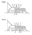
- the summation planetary gear 330 (FIG. 22) likewise consists of a first planetary gear stage with the sun gear 301, the land 302 and the ring gear 303 and a second planetary gear stage with the sun gear 304, the land 305 and the ring gear 306.
- the first shaft of the summation planetary gear 330 forms the web 302 of the first planetary gear stage
- the second shaft the ring gear 306 of the second planetary gear stage.
- the third shaft is connected to the ring gear 303 of the first planetary gear stage and the web 305 of the second planetary gear stage
- the fourth shaft of the summation planetary gear is connected to the sun gear 301 of the first planetary gear stage and to the sun gear 304 of the second planetary gear stage.
- the various designs of the summation planetary gear 130, 230, 330 are alternative solutions to the design of the summation planetary gear 30. Depending on the specific requirements when equipping different vehicles, there is a specific choice.
- the hydrostatic components are operated in an oil-free housing in order to improve the transmission efficiency.
- the feed and flush valves are - as is also known - designed so that the oil not required for leak oil compensation, which is used in particular for flushing and cooling the hydrostatic system, is not sprayed into the hydrostatic housing, but, if necessary, other consumers, such as Area couplings, lubrication devices, etc., supplied, and the rest can preferably be performed via the oil cooler.
- two shuttle valves arranged on both sides are preferably used, as they are known in principle as a feed valve for hydrostatics, one for the feed and the other valve releasing the low-pressure flow after the hydrostatic rinsing and cooling to the mentioned secondary consumers and possibly to the cooler .
- Both valves are - as is well known in the case of feed and flush valves - controlled by the respective high pressure, which closes the path to the high pressure side and at the same time opens the oil passage on both sides under low pressure.
- the first range clutch 10 or reverse range clutch 22; 22a; 27 are used as a starting clutch which, with the appropriate design, bridges the speed spread (FIG. 7, see line 37) and the first starting range up to translation point "X".
- the area clutch serving as a starting clutch can be activated with the same signals as the bypass valve 55.
Description
Die Erfindung bezieht sich auf ein stufenloses hydrostatisch-mechanisches Verzweigungsgetriebe für Kraftfahrzeuge nach dem Oberbegriff des Anspruchs 1. Ein solches hydrostatisch-mechanisches Getriebe mit Leistungsverzweigung und mit einem vierwelligen Summierungsplaneten-Getriebe ist aus der EP-A 081 696 bekannt.The invention relates to a continuously variable hydrostatic-mechanical branching transmission for motor vehicles according to the preamble of
Die noch bestehenden Probleme bei Anwendung des Hydrostaten im Kraftfahrzeug, insbesondere für den anspruchsvollen Personenverkehr, liegen im unbefriedigenden Wirkungsgrad und im Geräuschverhalten begründet.The problems that still exist when using the hydrostat in the motor vehicle, in particular for demanding passenger traffic, are due to unsatisfactory efficiency and noise behavior.
Der Erfindung liegt die Aufgabe zugrunde, das bekannte Getriebe zu verbessern, insbesondere ein stufenloses hydrostatisch-mechanisches Verzweigungsgetriebe zu schaffen, das die spezifischen Anforderungen an den Hydrostaten auf ein Mindestmaß senkt, d.h. das den hydrostatischen Leistungsanteil reduziert und die geräusch-, wirkungsgrad- und lebensdauerbestimmenden Parameter, wie Hydrostatdruck, Hydrostatdrehzahlen sowie die Größe dieser Komponenten und deren Anordnung in ein akzeptables und technisch machbares Maß bringt. Darüber hinaus soll eine weitgehende Anpassungsfähigkeit an verschiedene fahrzeugspezifische Bedingungen erfüllbar sein. Das Drehzahlniveau soll so liegen, daß sich eine abtriebsseitige Ubersetzungsanpassung durch zusätzliche Übersetzungsstufen möglichst erübrigt. Es soll neben hoher Wirtschaftlichkeit im Betrieb, also durch Verbrauchseinsparung durch Ausnutzung der Verbrauchsbestwerte des Motors etc., ein hoher Wirtschaftlichkeitsgrad, auch durch eine risikofreie rationelle Fertigung, erzielt werden. Des weiteren sollen eine montage- und servicefreundliche Modulbauweise realisierbar und kompakte, fahrzeugfreundliche Gesamtkonstruktionen möglich sein.The object of the invention is to improve the known transmission, in particular to provide a continuously variable hydrostatic-mechanical branching transmission which reduces the specific requirements for the hydrostats to a minimum, i.e. that reduces the hydrostatic power share and brings the noise, efficiency and service life-determining parameters, such as hydrostatic pressure, hydrostatic speeds and the size of these components and their arrangement to an acceptable and technically feasible level. In addition, it should be possible to largely adapt to different vehicle-specific conditions. The speed level should be such that an adaptation on the output side by additional gear ratios is unnecessary. In addition to a high level of economy in operation, i.e. by saving consumption by utilizing the best consumption values of the engine, etc., a high level of economy should also be achieved through risk-free, rational production. Furthermore, an assembly and service-friendly modular construction should be feasible and compact, vehicle-friendly overall constructions should be possible.
Die Aufgabe wird durch die im Anspruch 1 aufgeführten Merkmale gelöst. Weitere, vorteilhafte Ausgestaltungen der Erfindung gehen aus den Unteransprüchen und der nachfolgenden Beschreibung hervor.The object is achieved by the features listed in
Die Erfindung wird an Ausführungsbeispielen anhand von Zeichnungen erläutert. Es zeigen
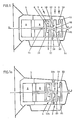
- Fig. 1 ein erstes Ausführungsbeispiel, schematisch,
- Fig. 1a ein zweites Ausführungsbeispiel, schematisch,
- Fig. 2 einen Drehzahlplan des ersten und zweiten Ausführungsbeispiels, jeweils mit Sekundärregelung,
- Fig. 3 einen Drehzahlplan des ersten und zweiten Ausführungsbeispiels ohne Sekundärregelung,
- Fig. 4 ein drittes Ausführungsbeispiel, schematisch,
- Fig. 5 einen Drehzahlplan des dritten Ausführungsbeispiels gemäß
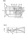
Figur 4, - Fig. 6 ein viertes Ausführungsbeispiel, schematisch,
- Fig. 7 einen Drehzahlplan des vierten Ausführungsbeispiels mit Drehzahlspreizung gemäß
Figur 6, - Fig. 8 einen Drehzahlplan des vierten Ausführungsbeispiels ohne Drehzahlspreizung gemäß
Figur 6, - Fig. 9 ein fünftes Ausführungsbeispiel mit drei Vorwärtsfahrbereichen und integriertem Rückwärtsfahrbereich, schematisch,
- Fig. 10 einen Drehzahlplan des Ausführungsbeispiels gemäß
Figur 9, - Fig. 11 ein sechstes Ausführungsbeispiel mit drei Vorwärtsfahrbereichen mit Drehzahlspreizung und separatem hydrostatischem Rückwärtsfahrbereich, schematisch,
- Fig. 12 einen Drehzahlplan für das Ausführungsbeispiel gemäß Fig. 11,
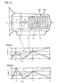
- Fig. 13 ein siebentes Ausführungsbeispiel mit drei Vorwärtsfahrbereichen und separatem, hydromechanischem Rückwärtsfahrbereich, schematisch,
- Fig. 14 einen Drehzahlplan für das Ausführungsbeispiel gemäß
Figur 13, - Fig. 15 einen Drehzahlplan für das Ausführungsbeispiel gemäß
Figur 13, mit Drehzahlspreizung im ersten Vorwärtsfahrbereich und im ersten Rückwärtsfahrbereich, - Fig. 16 ein achtes Ausführungsbeispiel mit zwei Vorwärtsfahrbereichen und einem separaten hydromechanischen Rück- und Vorwärtsfahrbereich zur Verwendung in Schwerkraftfahrzeugen,
- Fig. 17 ein neuntes Ausführungsbeispiel mit drei Vorwärtsfahrbereichen und einem separaten hydromechanischen Rückwärtsfahrbereich, für Schwerfahrzeuge, insbesondere für Raupenfahrzeuge,
- Fig. 18 ein zehntes Ausführungsbeispiel mit drei Vorwärtsfahrbereichen und drei hydromechanischen Rückwärtsfahrbereichen, für Schwerfahrzeuge.
- Fig. 19 ein anderes Ausführungsbeispiel einer Getriebeausführung, schematisch, mit kompaktem Kupplungspaket,
- Fig. 20 ein weiteres Ausführungsbeispiel des Getriebes mit ineinandergreifenden Planetenrädern des ersten Summierungsplanetengetriebes,
- Fig. 21 ein anderes Ausführungsbeispiel des Getriebes in einer weiteren Ausführungsform des Summierungsplanetengetriebes,
- Fig. 22 ein weiteres Ausführungsbeispiel des Getriebes mit einer vierten Ausführungsmöglichkeit des Summierungsplanetengetriebes,
- Fig. 23 ein weiteres Ausführungsbeispiel des Getriebes mitaufgeteilter, zweiter Summierungsplanetengetriebeeinheit.
- 1 shows a first embodiment, schematically,
- 1a shows a second embodiment, schematically,
- 2 shows a speed plan of the first and second exemplary embodiments, each with secondary control,
- 3 shows a speed plan of the first and second exemplary embodiment without secondary control,
- 4 shows a third exemplary embodiment, schematically,
- 5 shows a speed diagram of the third exemplary embodiment according to FIG. 4,
- 6 shows a fourth exemplary embodiment, schematically,
- 7 shows a speed plan of the fourth exemplary embodiment with speed spreading according to FIG. 6,
- 8 shows a speed plan of the fourth exemplary embodiment without speed spread according to FIG. 6,
- 9 shows a fifth exemplary embodiment with three forward driving ranges and integrated reverse driving range, schematically,
- 10 shows a speed diagram of the exemplary embodiment according to FIG. 9,
- 11 shows a sixth exemplary embodiment with three forward driving ranges with speed spread and separate hydrostatic reverse driving range, schematically,
- 12 is a speed map for the embodiment of FIG. 11,
- 13 shows a seventh exemplary embodiment with three forward driving ranges and a separate, hydromechanical reverse driving range, schematically,
- 14 shows a speed diagram for the exemplary embodiment according to FIG. 13,
- 15 shows a speed map for the exemplary embodiment according to FIG. 13, with speed spread in the first forward driving range and in the first reverse driving range,
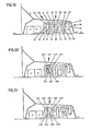
- 16 shows an eighth exemplary embodiment with two forward driving ranges and a separate hydromechanical reverse and forward driving range for use in gravity vehicles,
- 17 shows a ninth exemplary embodiment with three forward driving ranges and a separate hydromechanical reverse driving range, for heavy vehicles, in particular for caterpillar vehicles,
- 18 shows a tenth exemplary embodiment with three forward driving ranges and three hydromechanical reverse driving ranges, for heavy vehicles.
- 19 shows another exemplary embodiment of a transmission design, schematically, with a compact clutch pack,
- 20 shows a further exemplary embodiment of the transmission with intermeshing planet gears of the first summation planetary transmission,
- 21 shows another exemplary embodiment of the transmission in a further embodiment of the summation planetary transmission,
- 22 shows a further exemplary embodiment of the transmission with a fourth possible embodiment of the summation planetary transmission,
- 23 shows a further exemplary embodiment of the transmission with a split, second summation planetary gear unit.
Durch eine Kombination eines ersten Summierungsplanetengetriebes 4 (Fig. 1) mit einem zweiten Summierungsplanetengetriebe (5) wird erreicht, daß die Drehzahl einer zweiten Hydrostateinheit B im Anfahrbereich des Fahrzeugs gleichsinnig (Fig. 2, 3) mit der Antriebsdrehzahl ist. Die beiden Summierungsplanetengetriebe 4, 5 haben am Ende des ersten Schaltbereichs gegenläufige Drehrichtungen.A combination of a first summing planetary gear 4 (FIG. 1) with a second summing planetary gear (5) ensures that the speed of a second hydrostatic unit B in the starting area of the vehicle is in the same direction (FIG. 2, 3) with the drive speed. The two summation
Nach Umschaltung in den zweiten Fahrbereich wird die Drehzahl der Hydrostateinheit B wieder zurückgeführt, bis die Drehzahl einer Antriebswelle 2 erreicht ist. An diesem Punkt drehen alle Glieder des ersten Summierungsplanetengetriebes 4 sowie beide Hydrostateinheiten A, B und die Antriebswelle 2 gleichsinnig mit gleicher Drehzahl, also im Synchronlauf. Am Ende des zweiten Schaltbereichs ist die Übersetzung der Antriebswelle zur Abtriebswelle gleich 1. Ist die zweite Hydrostateinheit B als Verstelleinheit ausgebildet, kann durch sekundäre Verstellung die Abtriebszahl weiter erhöht werden, was für viele Anwendungsfälle zur Schaffung eines zusätzlichen Overdrivebereiches von Vorteil ist. Die Drehzahl der Abtriebswelle 3 ist hier noch verhältnismäßig niedrig, so daß die üblichen Übersetzungen der Kraftfahrzeuge verwendet werden können.After switching to the second driving range, the speed of the hydrostatic unit B is returned until the speed of a
Durch die Sekundärregelung (Fig. 2) kann der Rückwärtsfahrbereich ohne zusätzliche Kupplung oder sonstige Übersetzungsglieder realisiert werden. Der Aufbau des Getriebes ist relativ einfach. Alle Bauteile sind mit konventionellen Fertigungsmethoden herstellbar, und die Baugruppen, der Summierungsplanetengetriebe 4, 5 und das Kupplungspaket lassen sich auf einfache Art zu einer Baueinheit bzw. Montageeinheit kombinieren. Die Übersetzungen (Fig. 3) in den beiden Summierungsplanetengetrieben 4, 5 sind so ausgelegt, daß die Hydrostateinheit A im Anfahrpunkt noch nicht auf ihre maximale Endstellung ausgeschwenkt ist, sondern auf etwa 60 % ihrer Maximalverstellung. Bei Ausschwenkung der Hydrostateinheit A auf maximale Endverstellung ab diesem Punkt bekommt die Abtriebswelle 3 negative Drehzahl für Rückfahrgeschwindigkeit. Bei diesem Ausführungsbeispiel ist keine Sekundärverstellung erforderlich.Due to the secondary control (Fig. 2), the reverse range can be realized without an additional clutch or other transmission elements. The construction of the gearbox is relatively simple. All components can be manufactured using conventional manufacturing methods, and the assemblies, the summation
Bei einem anderen Ausführungsbeispiel (Fig. 1 a) dient anstelle der Kupplung 10 (erste Bereichskupplung) eine Bremse 1 Oa zum Festhalten des Stegs 17a als erste Bereichsschaltung. Die Antriebswelle 2 ist in diesem Fall unmittelbar mit dem Steg 21 der aus einem Hohlrad 19 und einem Sonnenrad 20 bestehenden Planetenstufe des zweiten Summierungsplanetengetriebes 5 verbunden. Am Ende des zweiten Schaltbereichs laufen hier alle Glieder des ersten Summierungsplanetengetriebes 4 und des zweiten Summierungsplanetengetriebes 5, der Kupplung 11 einschließlich der Antriebswelle 2 und beide Hydrostateinheiten A, B um. Durch den Wegfall der Relativdrehzahlen in diesem Bereich sind auch Wälzleistung und somit ebenfalls der Getriebewirkungsgrad sehr günstig. Durch die allgemein niedrigen Relativdrehzahlen im zweiten Bereich, der bei Anwendung auf einen PKW über 80 % Betriebsanteil hat, kann die Wälz- und Verlustleistung niedrig gehalten werden. Hierdurch bietet sich vor allem an, die Sekundärregelung des Hydrostatgetriebes A, B (siehe Drehzahllinie Bs) zugunsten eines großen Overdrivebereiches zu nutzen (Fig. 2), zumal dadurch auch gleichzeitig noch der Rückwärtsfahrbereich sehr kostengünstig realisiert werden kann.In another exemplary embodiment (FIG. 1 a), instead of the clutch 10 (first range clutch), a
Ein Ausführungsbeispiel gemäß Fig. 4 unterscheidet sich von demjenigen nach Figur 1 dadurch, daß eine zusätzliche Kupplung 12 für den Rückwärtsfahrbereich vorgesehen ist. Es wird hier eine unmittelbare Verbindung über die beiden Hohlräder des Summierungsplanetengetriebes 4 zur zweiten Hydrostateinheit B geschaffen, wodurch eine rein hydrostatische Übertragung im Rückwärtsfahrbereich bei geschlossener Kupplung 12 hergestellt wird. Bei diesem Ausführungsbeispiel kann der volle Verstellbereich des Hydrostatgetriebes im ersten Schaltbereich zugunsten einer höheren Leistungskapapzität gegenüber dem Ausführungsbeispiel gemäß Drehzahlplan in Figur 3 ausgenutzt werden, bei der der Rückwärtsfahrbereich im ersten Schaltbereich mit integriert ist (Fig. 5).An embodiment according to FIG. 4 differs from that according to FIG. 1 in that an additional clutch 12 is provided for the reverse driving range. A direct connection is created here via the two ring gears of the summation
Ein Ausführungsbeispiel gemäß Figur 6 weist einen separaten Rückwärtsschaltbereich durch den Zusatz eines weiteren Planetengetriebes 28 und einer Kupplung 27 bzw. Bremse 22 auf. Bei diesem Ausführungsbeispiel ist somit ein großer Rückwärtsfahrbereich möglich, wie man ihn allgemein bei PKW gewohnt ist. Diese Getriebekombination ist insbesondere bei Anwendung in Nutzkraftfahrzeugen oder Bussen oder auch bei Arbeitsmaschinen sehr zweckmäßig. Gegenüber vorgenannten Ausführungsbeispielen bietet sich hier die weitere Möglichkeit an, die Leistungskapazität des Getriebes weiter auszubauen, und zwar durch Spreizung des Drehzahlbereichs der zweiten Hydrostateinheit B. Das bedeutet, daß im Anfahrbereich die Drehzahl der zweiten Hydrostateinheit B gegenüber der ersten Hydrostateinheit A und somit der Antriebswelle 2 verhältnismäßig wesentlich höher ausgelegt werden kann, was zur Steigerung der Anfahrzugkräfte dient bzw. den Drehmomentwandlungsbereich des gesamten Getriebes erhöht. Dies kann dadurch realisiert werden, daß die Übersetzung im zweiten Summierungsplanetengetriebe 5 entsprechend dem gewünschten Spreizungsbereich angepaßt wird, wodurch man bewirkt, daß über das Summierungsplanetengetriebe im Anfahrzustand die zweite Hydrostateinheit B mit einer Drehzahl angetrieben wird, die höher als die der ersten Hydrostateinheit A liegt. Bei gleichgroßen Förder- bzw. Schluckvoluminas der Hydrostateinheit A zur Hydrostateinheit B bedeutet dies, daß eine Mehrförderung der Hydrostateinheit B gegeben ist, die durch eine Zusatzeinrichtung, z.B. über ein Bypaßventil 55 im Anfahrzustand zum Ausgleich auf die Niederdruckseite des Hydrostatkreislaufes gefördert wird. Die Anfahrregelung wird dadurch erreicht, daß das Bypaßventil 55 ein Signal 36 erhält, das entweder ein Drehzahlsignal oder/und ein Signal aus der Bremsbetätigung oder/und ein Lastsignal sein kann.An exemplary embodiment according to FIG. 6 has a separate reverse shifting range due to the addition of a further
Aus dem dem Ausführungsbeispiel nach Figur 6 zugeordneten Drehzahlplan (Fig. 7) ist die Drehzahlspreizung der Hydrostateinheit B durch eine unterbrochene Linie 37 dargestellt. Bei diesem Ausführungsbeispiel beträgt das maximale Drehzahlverhältnis Hydrostateinheit B zu Hydrostateinheit A 1:2. Die Funktion des Bypaßventils 55 ersetzt hier die Funktion einer Anfahrkupplung, wie dies bei einem anderen, aufwendigen Getriebe dieser Art bekannt ist.From the speed plan assigned to the exemplary embodiment according to FIG. 6 (FIG. 7), the speed spread of the hydrostatic unit B is represented by a
Anhand der Figur 9 wird ein weiteres Ausführungsbeispiel eines Getriebes mit drei Vorwärtsschaltbereichen beschrieben, wobei der Rückwärtsbereich im ersten Schaltbereich mitintegriert ist (wie aus dem dazugehörigen Drehzahlplan Fig. 10 hervorgeht). Die Grundbaueinheiten sind weitgehend mit den voranbeschriebenen Ausführungen identisch. Der Hauptunterschied liegt darin, daß das erste Summierungsplanetengetriebe 30 um einen weiteren, aus einem Hohlrad 31, einem Steg 32 und einem Sonnenrad 33 bestehenden Planetenradsatz erweitert ist. Die vierte Welle bildet hier das Sonnenrad 33, das beim Schalten des dritten Fahrbereichs über eine weitere Kupplung 35 mit der Abtriebswelle 3 verbunden ist. Bei diesem Ausführungsbeispiel ist der Rückwärtsbereich im ersten Schaltbereich mit integriert, wie im dazugehörigen Drehzahlplan (Fig. 10) dargestellt ist, der bei geschlossener Kupplung 10, die gleichzeitig auch für den ersten Fahrbereich dient, geschaltet ist. Der dritte Bereich kann hier durch einen relativ niedrigen Kostenaufwand realisiert werden, wodurch eine Verdoppelung des Drehmomentwandlungsbereichs, d.h. eine Verdoppelung der Leistungsfähigkeit des gesamten Getriebes erreicht wird. Die Abtriebsdrehzahl steigt bei diesem Ausführungsbeispiel um das Doppelte gegenüber der Antriebsdrehzahl an. Unter Berücksichtigung des von heutigen Brennkraftmaschinen angebotenen Einsparungspotentials sollte ein Overdrivebereich von etwa der doppelten Größe des Übersetzungsbereichs gewählt werden. Dies bedeutet, daß diese Getriebeausführung unter Beibehaltung der üblichen Achsübersetzung ideale Voraussetzungen bietet, um das angebotene Verbrauchseinsparungspotential, z.B. im PKW-Bereich voll ausschöpfen zu können. Diese Getriebeausführung zeichnet sich also durch einen sehr großen Wandlerbereich und somit ausreichenden Overdrivebereich bei gleichzeitig sehr kleinen Hydrostateinheiten aus, was den zusätzlichen Vorteil eines besonders günstigen Getriebewirkungsgrades und geringer spezifischer Belastung der Hydrostateinheiten gewährleistet. Auch den Geräuschproblemen wirkt dieses Ausführungsbeispiel entgegen.Another exemplary embodiment of a transmission with three forward shift ranges is described with reference to FIG. 9, the reverse range being integrated in the first shift range (as can be seen from the associated speed plan in FIG. 10). The basic building blocks are largely identical to the previously described versions. The main difference lies in the fact that the first summation
Werden höhere Rückfahrgeschwindigkeiten gefordert, kann die beschriebene Getriebeausführung gemäß einem weiteren Ausführungsbeispiel nach Figur 11 durch eine zusätzliche Kupplung für den Rückwärtsbereich, der rein hyrdostatisch wie bei der Ausführung nach Figur 4 über die Kupplung 12 geschaltet wird, erweitert werden. Bei diesem Ausführungsbeispiel kann der erste Fahrbereich mit Drehzahlspreizung der zweiten Hydrostateinheit B ähnlich dem Ausführungsbeispiel nach Figur 6 und nach Drehzahlplan Figur 7 zugunsten eines noch größeren Wandlungsbereichs entsprechend der hohen PKW-Leistungsklassen oder auch bei Anwendung in Nutzkraftfahrzeugen, Bussen oder Arbeitsmaschinen ausgeführt werden (Fig. 17, 18).If higher reversing speeds are required, the transmission design described can be expanded according to a further exemplary embodiment according to FIG. 11 by an additional clutch for the reverse range, which is switched purely hyrdostatically as in the embodiment according to FIG. 4 via
Besonders hohen Ansprüchen sowohl hinsichtlich der Leistungskapazität, der Fahrleistung wie des gesamten Fahrkomforts entspricht ein weiteres Ausführungsbeispiel gemäß Figur 13. Diese bietet drei Vorwärtsfahrbereiche und einen separaten leistungsverzweigten Rückwärtsfahrbereich, der in seiner Größe beliebig durch entsprechende Übersetzungsanpassung eines weiteren Planetensatzes und der Bereichsschaltung über eine Bremse 22a angepaßt werden kann. Der erste Fahrbereich ist ebenfalls mit einer Bereichsspreizung zugunsten eines großen Wandlungsbereichs ausführbar, der auch für den Rückwärtsbereich gilt. Die Größe der Rückfahrgeschwindigkeit kann durch eine Übersetzungsanpassung eines Planetengetriebes 28a den Erfordernissen angeglichen werden, was auch aus den dazugehörigen Drehzahlplänen (14, 15) hervor geht.A further exemplary embodiment according to FIG. 13 corresponds to particularly high demands both in terms of the power capacity, the driving performance and the overall driving comfort. This offers three forward driving ranges and a separate power-split reverse driving range, the size of which can be arbitrarily adjusted by adapting a further planetary gear set and the range switching via a
Ein weiteres Ausführungsbeispiel nach Figur 16 ist hinsichtlich seiner Grundbaueinheiten identisch mit dem Ausführungsbeispiel nach Figur 6. Es unterscheidet sich lediglich in der Anordnung der Hydrostateinheiten A, B, die hier zu den Bauelementen der Verzweigungsgetriebeeinheiten, also den Summierungsplantengetrieben 4, 5, dem Planetengetriebe 28 und der Kupplung 9 versetzt angeordnet sind, insbesondere im Hinblick auf Einbaubedingungen, wie sie bei Nutzkraftfahrzeugen, Bussen oder Arbeitsmaschinen gefordert werden. Der Antriebsmotor kann bei diesem Ausführungsbeispiel an verschiedenen Stellen angeschlossen werden. Hierzu stehen Antriebswellen 40, 42 und der Antriebsanschluß 43 zur Verfügung, was bei den geforderten vielfältigen Einbaubedingungen der Kraftfahrzeuge besonders vorteilhaft ist.A further exemplary embodiment according to FIG. 16 is identical in terms of its basic structural units to the exemplary embodiment according to FIG. 6. It differs only in the arrangement of the hydrostatic units A, B, which here are the components of the branching gear units, i.e. the summation
Ein anderes Ausführungsbeispiel (Fig. 17) entspricht im wesentlichen den Einbaubedingungen von Schwerkraftfahrzeugen, wie Bussen, Nutzkraftfahrzeugen, Arbeitsmaschinen und insbesondere Schleppern und besitzt drei Vorwärtsfahrbereiche und einen separaten Rückwärtsfahrbereich mit Leistungsverzweigung. Dieses Ausführungsbeispiel hat insbesondere für die Anwendung in Bussen besondere Vorteile hinsichtlich einer Kraftstoffeinsparung, Umweltfreundlichkeit und einem Fahrkomfort. Der dritte Bereich kann nahezu vollständig als Overdrivebereich für die Kraftstoffeinsparung genutzt werden.Another exemplary embodiment (FIG. 17) corresponds essentially to the installation conditions of gravity vehicles, such as buses, commercial vehicles, work machines and in particular tractors, and has three forward driving ranges and a separate reverse driving range with power split. This embodiment has particular advantages in terms of fuel savings, environmental friendliness and driving comfort, particularly for use in buses. The third area can be used almost entirely as an overdrive area for fuel savings.
Für Fahrzeuge mit hoher Rückfahrgeschwindigkeit bietet ein weiteres Ausführungsbeispiel (Fig. 18) drei Vorwärtsfahrbereiche und drei Rückwärtsfahrbereiche, wobei der Rückwärtsfahrbereich in der Gesamtgeschwindigkeit durch ein zusätzliches Planetenwendegetriebe 44 beliebig angepaßt werden kann. Dieses Ausführungsbeispiel ist besonders für Arbeitsmaschinen, wie Planierraupen oder beliebige Kettenfahrzeuge von Vorteil. Die Gesamtcharakteristik entspricht der Getriebeausführung nach dem Ausführungsbeispiel gemäß Figur 13, wobei der gesamt Vorwärtsfahrbereich durch das Planetenwendegetriebe 44 und eine Kupplung/Bremse 45 umgekehrt wird. Wie auch die Ausführungen gemäß Figuren 16 und 17 bietet auch dieses Ausführungsbeispiel den Vorteil der verschieden Anschlußmöglichkeiten für die Brennkraftmaschine.For vehicles with a high reversing speed, a further exemplary embodiment (FIG. 18) offers three forward driving ranges and three reverse driving ranges, the total reverse speed of the reversing range being able to be adapted as desired by means of an additional
Das Verzweigungsgetriebe weist den Vorteil auf, daß alle Bauteile einfach herstell- und montierbar sind, daß also nahezu eine risikofreie Fertigung gewährleistet ist. Ferner ist bei allen Ausführungsbeispielen eine Modulbauweise realisierbar, die hohe Servicefreundlichkeit hat. Die einzelnen Baugruppen, nämlich das erste Summierungsplanetengetriebe, das zweite Summierungsplanetengetriebe, das Kupplungspaket sowie die Zusatzelemente für die Erreichung der Rückfahrgeschwindigkeiten, können zu Einzelbaugruppen zusammengefaßt werden. Je nach Getriebeausführung können die Einzelbaugruppen ihrerseits zu einer Hauptgruppe zusammengeschlossen werden, wie z.B. bei den Ausführungsbeispielen nach den Figuren 16, 17, 18, bei denen jeweils das zweite Summierungsplanetengetriebe, das Kupplungspaket und die Wendegetriebe- bzw. Rückfahreinrichtung durch ein alle Gruppen übergreifendes Gehäuse 46, 47 zu einem Baustein zusammengefaßt sind, der auf einfache Weise in das Getriebegehäuse eingesetzt und dort fixiert werden kann, wodurch Gehäusebearbeitungen auf ein geringes Maß gesenkt werden können. Ferner kann der Vorteil vielfältiger Varationsmöglichkeiten hinsichtlich eines breiten Anwendungsbereichs ausgeschöpft werden.The branching gear has the advantage that all components are easy to manufacture and assemble, so that almost risk-free production is guaranteed. In addition, in all of the exemplary embodiments, a modular construction can be implemented which is extremely easy to service. The individual assemblies, namely the first summing planetary gear, the second summing planetary gear, the clutch pack and the additional elements for achieving the reversing speeds, can be combined to form individual assemblies. Depending on the transmission design, the individual assemblies can in turn be combined to form a main group, such as in the exemplary embodiments according to FIGS. 16, 17, 18, in which the second summation planetary transmission, the clutch pack and the reversing gear or reversing device are provided by a
Die Antriebswelle 2 (Fig. 1), die ohne Trennkupplung mit der Kurbelwelle des Antriebsmotors verbunden ist, treibt die erste Hydrostateinheit A sowie die erste Welle des Summierungsplantengetriebes 4 unmittelbar an, wobei die Welle bei diesem Ausführungsbeispiel als Hohlrad ausgebildet ist. Ist das Getriebe gemäß Drehzahlplan nach Figur 2 ausgelegt, haben die erste Hydrostateinheit A und die zweite Hydrostateinheit B gleiche Drehzahl und gleiche Drehrichtung, was bedeutet, daß alle Glieder des Summierungsplanetengetriebes 4 Synchronlauf haben. Mit der zweiten Hydrostateinheit B steht eine Welle des ersten Summierungsplanetengetriebes 4 und die erste Welle des zweiten Summierungsplanetengetriebes 5, die beide als Sonnenräder 8, 16 ausgebildet sind, in trieblicher Verbindung. Die hydrostatische Leistung teilt sich dementsprechend auf beide Summierungsplaneten- getriebe 4, 5 auf.The drive shaft 2 (FIG. 1), which is connected to the crankshaft of the drive motor without a clutch, drives the first hydrostatic unit A and the first shaft of the summation
Die im ersten Summierungsplanetengetriebe 4 über den Steg 7 aufsummierte Leistung wird im ersten Fahrbereich auf das Sonnenrad 20 der zweiten Summierungsplanetengetriebeeinheit übertragen, wobei gleichzeitig zusätzlich eine Teilleistung über die beiden Hohlräder 18, 19 des zweiten Summierungsplanetengetriebes 5 fließt, die der Summenleistung des Sonnenrads 20 im Steg 21 des zweiten Summierungsplanetengetriebes 5 zusätzlich aufsummiert, und die gemeinsam bei geschlossener Kupplung 10 für den ersten Fahrbereich zur Abtriebswelle 3 weitergeleitet wird. Im Anfahrzustand ist die erste Hydrostateinheit A auf ihre volle Verstellgröße eingeregelt. Wird die Hydrostateinheit A jetzt auf kleiner Verstellwerte eingeregelt, beginnen sich der Steg 21 und damit die Abtriebswelle 3 zu drehen. Bei einer Hydrostatverstellung über die Null-Lage hinaus bis zu der maximal negativen Endverstellung haben alle Glieder der Kupplungen 10, 11 Synchronlauf erreicht, so daß die Umschaltung in den zweiten Bereich durch Schließen der Kupplung 11 und Öffnen der Kupplung 10 erfolgen kann. Hierbei wird eine direkte Verbindung der Abtriebswelle 3 mit der dritten Welle des ersten Summierungsplanetengetriebes 4, dem Steg 7, hergestellt. Das zweite Summierungsplanetengetriebe 5 ist innerhalb des zweiten Schaltbereichs voll entlastet. Ist die zweite Hydrostateinheit B als Verstelleinheit ausgebildet, kann der zweite Bereich durch Sekundärregelung zugunsten eines größeren Overdrivebereiches erweitert werden. Der erweiterte Sekundärregelbereich ist in Figur 2 durch die unterbrochene Linie Bs dargestellt. Für den Rückwärtsfahrbereich kann ebenfalls die Sekundärregelung der Hydrostateinheit B dienen. Der aus der Hydrostateinheit A und der Hydrostateinheit B bestehende Hydrostat wird nun wieder auf Null und darüberhinaus bis am Ende des zweiten Schaltbereichs alle Glieder des ersten Summierungsplanetengetriebes 4 Gleichlauf erreicht haben zurückgeregelt.The power added up in the first summing
Der beschriebene Funktionsablauf innerhalb des ersten und zweiten Fahrbereichs ist bei den übrigen Ausführungsbeispielen gleichartig. Bei den Ausführungsbeispielen mit drei Rückwärtsfahrbereichen, z.B. nach Figur 9 mit Drehzahlplan gemäß Figur 10, erfolgt die Umschaltung in den dritten Fahrbereich bei Synchronlauf aller Glieder des ersten Summierungsplanetengetriebes 30 bei gleichzeitigem Gleichlauf aller Glieder der beiden Kupplungen 11 und 35. Im dritten Fahrbereich wird der Hydrostat nun nochmals voll innerhalb seines vollständigen positiven und negativen Verstellbereichs durchfahren.The functional sequence described within the first and second driving range is the same in the other exemplary embodiments. In the embodiments with three reverse driving ranges, e.g. According to FIG. 9 with the speed plan according to FIG. 10, the changeover to the third driving range takes place with synchronous operation of all elements of the first summation
Zum Starten des Motors ist die erste Hydrostateinheit A auf ein Fordervolumen "Null" durch z.B. eine mechanische Federzentrierung, wie sie bei einfachen Hydrostatantrieben bekannt ist, eingestellt, um vor allem im kalten Zustand die Motorstartwiderstände durch die Strömungswiderstände im Hydrostatkreislauf zu vermeiden.To start the engine, the first hydrostatic unit A is set to a delivery volume "zero" by e.g. a mechanical spring centering, as is known in simple hydrostatic drives, is set in order to avoid engine starting resistances due to the flow resistances in the hydrostatic circuit, especially in the cold state.
Zur Verbesserung des Getriebewirkungsgrades bzw. zur Vermeidung unnötiger Betriebsverluste wird der Öldruck zum Schließen der Bereichskupplungen und zur Versorgung des Hydrostatkreislaufes u.a. entsprechend den jeweiligen Lastzuständen, wie an sich bekannt, angepaßt, durch lastabhängige Modulation z.B. über den Hochdruck des Hydrostatgetriebes.To improve the transmission efficiency or to avoid unnecessary operating losses, the oil pressure is used to close the area clutches and to supply the hydrostatic circuit, among other things. adapted to the respective load conditions, as is known per se, by load-dependent modulation e.g. about the high pressure of the hydrostatic transmission.
Ein weiterer Vorteil besteht darin, daß die Verstellge schwindigkeit des Getriebes den jeweiligen Betriebsbedingungen angepaßt werden kann, durch entsprechende lastabhängige Regelung z.B. durch ein regelbares Drosselventil zur Dosierung der ÖImenge eines Verstellzylinders über den Hochdruck des Hydrostatgetriebes. Die Bereichsschaltungen sind nahezu nahtlos, da diese im Synchronlauf der Kupplungselemente vollzogen werden und, wie an sich bekannt, eine Lastüberschneidung haben, wobei kurzzeitig beide Kupplungen geschlossen sind.Another advantage is that the speed of the gearbox can be adjusted to the respective operating conditions, e.g. thanks to an adjustable throttle valve for dosing the amount of oil in an adjusting cylinder via the high pressure of the hydrostatic transmission. The range shifts are almost seamless since they are carried out in synchronism with the coupling elements and, as is known per se, have a load overlap, with both clutches being closed for a short time.
Ein anderes Ausführungsbeispiel des Verzweigungsgetriebes (Fig. 19) zeichnet sich durch eine besonders kompakte Bauweise aus. Die mit höherem Drehmoment belastete Bereichskupplung 10 für den ersten Vorwärtsfahrbereich und die ebenfalls mit höherem Drehmoment belastete Bereichskupplung 27 für den Rückwärtsfahrbereich sind über die beiden weniger drehmomentbelasteten Kupplungen 11, 35 des zweiten Fahrbereichs und des dritten Fahrbereichs angeordnet. Hierdurch kann das gesamte Kupplungspaket auf kurze Bauweise gebracht werden.Another exemplary embodiment of the branching transmission (FIG. 19) is distinguished by a particularly compact design. The area clutch 10 loaded with higher torque for the first forward travel area and the area clutch 27 also loaded with higher torque for the reverse travel area are arranged via the two less torque-loaded
Ein weiterer Vorteil besteht darin, daß die Ölzuführungen für alle Bereichskupplungen 10, 11, 35, 27 unmittelbar über die zur Abtriebswelle 3 führende Welle erfolgen kann. Alle Kupplungen haben ein gemeinsames Kupplungsglied, über das auf kostengünstigem Weg die unmittelbare Ölzuführung zu den Kupplungen untergebracht werden kann. Das Wendeplanetengetriebe 28 ist abtriebsseitig nach dem Kupplungspaket angeordnet, wobei dessen Hohlrad 23 mit dem Steg 21 der zweiten Summierungsplanetengetriebeeinheit 5 und einem Kupplungsglied der ersten Bereichskupplung 10 verbunden ist. Der Steg 25 der Wendeplanetengetriebestufe 28 ist gehäusefest, und das Sonnenrad 26 mit einem Glied der Kupplung 27 des Rückwärtsfahrbereichs verbunden.Another advantage is that the oil supply for all range
Das erste Summierungsplanetengetriebe 130, 230, 330 kann, wie in den Figuren 20, 21, 22 dargestellt, verschieden ausgeführt werden. Das Summierungsplanetengetriebe 130 (Fig. 20) besitzt zwei ineinandergreifende erste Planetenräder 131 und zweite Planetenräder 132, die gemeinsam auf einem Steg 107 gelagert sind. Die erste Welle des Summierungsplanetengetriebes 130 ist mit dem Hohlrad 106, das in erste Planetenräder 131 eingreift, die zweite Welle mit dem Sonnenrad 108, das ebenfalls in erste Planetenräder 131 eingreift, und die vierte Welle mit dem Sonnenrad 133, das mit zweiten Planetenrädern 132 kämmt, verbunden. Die dritte Welle bildet den Steg für die Planetenräder 131, 312.The first summation
Das Summierungsplanetengetriebe (Fig. 21) besteht aus einer ersten Planetenstufe mit dem Sonnenrad 208, den Planetenrädern 213 und dem Hohlrad 206 sowie einer zweiten Planetengetriebestufe mit dem Sonnenrad 210 aus ineinandergreifenden Planetenrädern 211, 212 und dem Hohlrad 207. Die erste Welle des Summierungsplanetengetriebe 230 ist mit dem Hohlrad 206 der ersten Planetengetriebestufe und dem Hohlrad 207 der zweiten Planetengetriebestufe verbunden. Die zweite Welle mit dem Sonnenrad 208 der ersten Planetengetriebestufe und die dritte Welle stellen den Steg 209 für beide Planetengetriebestufen dar. Die vierte Welle des Summierungsplanetengetriebes wird über das Sonnenrad 210 angetrieben.The summation planetary gear (FIG. 21) consists of a first planetary stage with the
Das Summierungsplanetengetriebe 330 (Fig. 22) besteht ebenfalls aus einer ersten Planetengetriebestufe mit dem Sonnenrad 301, dem Steg 302 und dem Hohlrad 303 sowie einer zweiten Planetengetriebestufe mit dem Sonnenrad 304, dem Steg 305 und dem Hohlrad 306. Die erste Welle des Summierungsplanetengetriebes 330 bildet den Steg 302 der ersten Planetengetriebestufe, die zweite Welle das Hohlrad 306 der zweiten Planetengetriebestufe. Die dritte Welle ist mit dem Hohlrad 303 der ersten Planetengetriebestufe und dem Steg 305 der zweiten Planetengetriebestufe verbunden, und die vierte Welle des Summierungsplanetengetriebe mit dem Sonnenrad 301 der ersten Planetengetriebestufe sowie mit dem Sonnenrad 304 der zweiten Planetengetriebestufe.The summation planetary gear 330 (FIG. 22) likewise consists of a first planetary gear stage with the
Die verschiedenen Ausführungen der Summierungsplanetengetriebe 130, 230, 330 sind Alternativlösungen zur Ausführung des Summierungsplanetengetriebes 30. Je nach jeweiligen spezifischen Forderungen bei Ausstattung verschiedener Fahrzeuge ist eine gezielte Auswahlmöglichkeit gegeben.The various designs of the summation
Zur Verbesserung des Getriebewirkungsgrades werden - wie an sich bekannt - die Hydrostatkomponenten im ölleeren Gehäuse betrieben. Die Einspeise- und Spülventile sind hierbei - wie ebenfalls bekannt - so ausgebildet, daß das nicht für den Leckölausgleich benötigte Öl, was insbesondere zur Spülung und Kühlung der Hydrostatanlage dient, nicht in das Hydrostatgehäuse abgespritzt wird, sondern, falls erforderlich, weiteren Verbrauchern, wie Bereichskupplungen, Schmiereinrichtungen etc., zugeführt, und der Rest vorzugsweise über den Ölkihler geführt werden kann. Zu diesem Zweck werden vorzugsweise zwei beidseitig angeordnete Wechselventile verwendet, wie sie prinzipiell allgemein als Einspeiseventil für Hydrostatik bekannt sind, wobei das eine für die Einspeisung, und das andere Ventil den Niederdruckdurchfluß nach der Hydrostatspülung und -kühlung zu den genannten Nebenverbrauchern und gegebenenfalls zum Kühler freigibt. Beide Ventile werden - wie bei Einspeise- und Spülventilen allgemein bekannt - durch den jeweiligen Hochdruck angesteuert, wodurch der Weg zur Hochdruckseite verschlossen und gleichzeitig der beidseitige Öldurchgang unter Niederdruck freigegeben wird.As is known per se, the hydrostatic components are operated in an oil-free housing in order to improve the transmission efficiency. The feed and flush valves are - as is also known - designed so that the oil not required for leak oil compensation, which is used in particular for flushing and cooling the hydrostatic system, is not sprayed into the hydrostatic housing, but, if necessary, other consumers, such as Area couplings, lubrication devices, etc., supplied, and the rest can preferably be performed via the oil cooler. For this purpose, two shuttle valves arranged on both sides are preferably used, as they are known in principle as a feed valve for hydrostatics, one for the feed and the other valve releasing the low-pressure flow after the hydrostatic rinsing and cooling to the mentioned secondary consumers and possibly to the cooler . Both valves are - as is well known in the case of feed and flush valves - controlled by the respective high pressure, which closes the path to the high pressure side and at the same time opens the oil passage on both sides under low pressure.
Anstelle des Bypaßventils 55 (Fig. 7) kann für den Anfahrvorgang auch die erste Bereichskupplung 10 bzw. Rückwärtsbereichskupplung 22; 22a; 27 als Anfahrkupplung benutzt werden, die bei entsprechender Ausbildung die Drehzahlspreizung (Fig. 7, siehe Linie 37) und den ersten Anfahrbereich bis Übersetzungspunkt "X" überbrückt. Die als Anfahrkupplung dienende Bereichskupplung kann mit gleichen Signalen, wie das Bypaßventil 55 angesteuert werden.Instead of the bypass valve 55 (FIG. 7), the first range clutch 10 or reverse range clutch 22; 22a; 27 are used as a starting clutch which, with the appropriate design, bridges the speed spread (FIG. 7, see line 37) and the first starting range up to translation point "X". The area clutch serving as a starting clutch can be activated with the same signals as the
Claims (26)
Applications Claiming Priority (4)
| Application Number | Priority Date | Filing Date | Title |
|---|---|---|---|
| DE3533191 | 1985-09-18 | ||
| DE3533191 | 1985-09-18 | ||
| DE19863622045 DE3622045A1 (en) | 1985-09-18 | 1986-07-01 | CONTINUOUSLY HYDROMECHANICAL BRANCHING GEARBOX, ESPECIALLY FOR MOTOR VEHICLES |
| DE3622045 | 1986-07-01 |
Publications (3)
| Publication Number | Publication Date |
|---|---|
| EP0222108A2 EP0222108A2 (en) | 1987-05-20 |
| EP0222108A3 EP0222108A3 (en) | 1987-08-26 |
| EP0222108B1 true EP0222108B1 (en) | 1990-12-05 |
Family
ID=25836081
Family Applications (1)
| Application Number | Title | Priority Date | Filing Date |
|---|---|---|---|
| EP86112723A Expired - Lifetime EP0222108B1 (en) | 1985-09-18 | 1986-09-15 | Continuous power dividing hydromechanical transmission, especially for motor vehicles |
Country Status (2)
| Country | Link |
|---|---|
| EP (1) | EP0222108B1 (en) |
| DE (1) | DE3622045A1 (en) |
Families Citing this family (25)
| Publication number | Priority date | Publication date | Assignee | Title |
|---|---|---|---|---|
| DE3838768A1 (en) * | 1987-05-12 | 1989-06-08 | Jarchow Friedrich | Hydrostatic/mechanical power-shift transmission with a continuously variable effect and with toothed selector clutches for shifts proprietary to gear changes and multi-plate clutches for the gear changes |
| DE3838767A1 (en) * | 1987-05-12 | 1989-06-08 | Jarchow Friedrich | Hydrostatic/mechanical power-shift transmission with a continuously variable effect and a high-quality gear change |
| DE3815780A1 (en) * | 1987-05-12 | 1988-12-01 | Jarchow Friedrich | Hydrostatic-mechanical power-shift transmission with a continuous effect |
| GB8720639D0 (en) * | 1987-09-02 | 1987-10-07 | Lcvt Ltd | Continuously variable transmission |
| DE3730474A1 (en) * | 1987-09-11 | 1989-03-23 | Michael Meyerle | CONTINUOUSLY HYDROSTATIC-MECHANICAL BRANCHING GEARBOX, ESPECIALLY FOR MOTOR VEHICLES |
| DE3909939A1 (en) * | 1988-03-30 | 1989-10-19 | Zahnradfabrik Friedrichshafen | Change-under-load transmission (powershift transmission) |
| DE3821290A1 (en) * | 1988-06-24 | 1989-12-28 | Man Nutzfahrzeuge Ag | DRIVE DEVICE OF A VEHICLE |
| DE4042697C2 (en) * | 1989-09-02 | 2001-03-29 | Ingbuero Michael Meyerle | Infinitely variable hydrostatic transmission |
| GB9011806D0 (en) * | 1990-05-25 | 1990-07-18 | Egan Michael J | Rotary transmission system |
| DE4313378C2 (en) * | 1993-04-23 | 1997-04-30 | Renk Ag | Automatic powershift transmission with continuously adjustable translation |
| FR2809154A1 (en) * | 2000-05-17 | 2001-11-23 | Timothee Biel | Differential transmission for car has two epicycloidal trains in parallel between the inlets and exits, which cooperate via an additional element |
| DE102006061116A1 (en) * | 2006-12-22 | 2008-06-26 | Audi Ag | Power-branching vehicle drive has drive shaft connected mechanically and via hydrostatic pump unit to summation drive, pump unit being connected by sun wheel to shaft and via planet carrier and planet wheel to sun wheel of summation drive |
| DE102007047194A1 (en) | 2007-10-02 | 2009-04-09 | Zf Friedrichshafen Ag | Power split transmission |
| US8393988B2 (en) | 2007-10-02 | 2013-03-12 | Zf Friedrichshafen Ag | Transmission device for a vehicle |
| ATE537384T1 (en) | 2007-10-02 | 2011-12-15 | Zahnradfabrik Friedrichshafen | CONTINUOUSLY VARIABLE TRANSMISSION DEVICE FOR A VEHICLE |
| US8262525B2 (en) | 2007-10-02 | 2012-09-11 | Zf Friedrichshafen Ag | Hydrostatic-mechanical power split transmission |
| ATE533970T1 (en) | 2007-10-02 | 2011-12-15 | Zahnradfabrik Friedrichshafen | TRANSMISSION DEVICE WITH A VARIATOR |
| JP5190513B2 (en) | 2007-10-02 | 2013-04-24 | ツェットエフ、フリードリッヒスハーフェン、アクチエンゲゼルシャフト | Power split transmission |
| DE102007047195A1 (en) | 2007-10-02 | 2009-04-09 | Zf Friedrichshafen Ag | Adjustment of the stroke volume of hydraulic piston machines |
| JP5306361B2 (en) | 2007-10-02 | 2013-10-02 | ツェットエフ、フリードリッヒスハーフェン、アクチエンゲゼルシャフト | Stroke volume adjuster for hydraulic piston machine |
| ATE533969T1 (en) | 2007-10-02 | 2011-12-15 | Zahnradfabrik Friedrichshafen | POWER SPLIT TRANSMISSION |
| DE102008040450A1 (en) * | 2008-07-16 | 2010-01-21 | Zf Friedrichshafen Ag | Variable transmission device for vehicle, has variator, planetary gear unit, and manual gear unit, which are arranged in transmission housing |
| ATE534849T1 (en) | 2007-10-02 | 2011-12-15 | Zahnradfabrik Friedrichshafen | TRANSMISSION DEVICE FOR A VEHICLE HAVING A VARIATOR |
| DE102014223213A1 (en) | 2014-11-13 | 2016-05-19 | Zf Friedrichshafen Ag | Range gear and method of operating a range gear |
| DE102017219995A1 (en) * | 2017-11-10 | 2019-05-16 | Zf Friedrichshafen Ag | Stepless power split transmission |
Citations (1)
| Publication number | Priority date | Publication date | Assignee | Title |
|---|---|---|---|---|
| EP0081696A1 (en) * | 1981-12-01 | 1983-06-22 | Friedrich Prof. Dr.-Ing. Jarchow | Hydrostatic-mechanical transmission with input split power |
Family Cites Families (11)
| Publication number | Priority date | Publication date | Assignee | Title |
|---|---|---|---|---|
| GB1411909A (en) * | 1971-06-21 | 1975-10-29 | Orshansky Transmission Corp | Hydrochemical transmission |
| US3855879A (en) * | 1972-12-22 | 1974-12-24 | G Delalio | Synchronously shiftable dual range planetary transmission with coaxial input shafts |
| JPS5623069B2 (en) * | 1974-02-06 | 1981-05-28 | ||
| US4116089A (en) * | 1977-04-14 | 1978-09-26 | Orshansky Transmission Corporation | Hydromechanical transmission |
| DE2716960C2 (en) * | 1977-04-16 | 1984-08-23 | Zahnradfabrik Friedrichshafen Ag, 7990 Friedrichshafen | Hydrostatic-mechanical transmission with power split |
| DE2757191C2 (en) * | 1977-12-22 | 1983-01-13 | Zahnradfabrik Friedrichshafen Ag, 7990 Friedrichshafen | Infinitely adjustable hydrostatic-mechanical compound transmission |
| DE2757300C2 (en) * | 1977-12-22 | 1982-08-12 | Zahnradfabrik Friedrichshafen Ag, 7990 Friedrichshafen | Power-split hydrostatic-mechanical compound transmission |
| DE2758659C3 (en) * | 1977-12-29 | 1982-03-18 | Zahnradfabrik Friedrichshafen Ag, 7990 Friedrichshafen | Hydrostatic-mechanical transmission with power split |
| US4261229A (en) * | 1978-08-24 | 1981-04-14 | Aisin Seiki Kabushiki Kaisha | Automatic speed ratio control system for stepless transmission of automotive vehicles |
| DE2854375C2 (en) * | 1978-12-16 | 1982-06-24 | Zahnradfabrik Friedrichshafen Ag, 7990 Friedrichshafen | Hydrostatic-mechanical compound transmission |
| DE2935361C2 (en) * | 1979-09-01 | 1985-07-18 | Daimler-Benz Ag, 7000 Stuttgart | Automatic planetary gear change transmission for heavy vehicles with a permanent brake |
-
1986
- 1986-07-01 DE DE19863622045 patent/DE3622045A1/en active Granted
- 1986-09-15 EP EP86112723A patent/EP0222108B1/en not_active Expired - Lifetime
Patent Citations (1)
| Publication number | Priority date | Publication date | Assignee | Title |
|---|---|---|---|---|
| EP0081696A1 (en) * | 1981-12-01 | 1983-06-22 | Friedrich Prof. Dr.-Ing. Jarchow | Hydrostatic-mechanical transmission with input split power |
Also Published As
| Publication number | Publication date |
|---|---|
| EP0222108A3 (en) | 1987-08-26 |
| DE3622045C2 (en) | 1988-12-08 |
| EP0222108A2 (en) | 1987-05-20 |
| DE3622045A1 (en) | 1987-03-26 |
Similar Documents
| Publication | Publication Date | Title |
|---|---|---|
| EP0222108B1 (en) | Continuous power dividing hydromechanical transmission, especially for motor vehicles | |
| EP0263856B1 (en) | Continuous speed-change branched gear, in particular for motor vehicles | |
| EP0195452B1 (en) | Contunuously variable compound power shift transmission of the range-speed type with multiple power path | |
| EP1626206B1 (en) | Torque split transmission for motor vehicles | |
| DE2854375A1 (en) | HYDROSTATIC-MECHANICAL GEARBOX WITH POWER BRANCHING | |
| DE202008017570U1 (en) | Power-shiftable multi-speed transmission | |
| WO1999015813A2 (en) | Continuously variable transmission, especially with power branching | |
| EP0238521B1 (en) | Branched infinitely-variable hydromechanical transmission for motor vehicles | |
| DE4106746A1 (en) | Four-shaft summing gear drive for hydrostatic-mechanical drive - has two planet gears on branch shaft with its two output shafts selectively connected to second downstream gear drive | |
| DE19944792A1 (en) | Infinitely variable retro-fit gear for small tractor power take-off point, with either hydrostatic or mechanical converter to transmit small proportion of engine power | |
| EP0291525B1 (en) | Infinitely variable driving and steering gear for tracklaying vehicles | |
| DE2815831A1 (en) | GEAR ARRANGEMENT WITH HYDROSTATIC START-UP LEVEL AND TWO HYDROMECHANICAL GEAR LEVELS | |
| DE2423626B2 (en) | CONTINUOUSLY POWER-SPANISHING COMPOUND TRANSMISSION | |
| EP0397804B1 (en) | Powershift gearbox with infinitely variable ratio | |
| EP0386214B1 (en) | Hydromechanically infinitely variable transmission with power splitting, in particular for motor vehicles | |
| DE4027724A1 (en) | Infinitely variable hydrostatic transmission - with planetary gearing and selected drive connections for multiple gear ratios and with several reverse ratios | |
| DE19621201A1 (en) | Infinitely variable automotive gear box | |
| EP0242372B1 (en) | Continuously-variable hydromechanical parallel-type gear-box, in particular for motor vehicles | |
| DE3341217A1 (en) | Motor vehicle automatic transmission | |
| DE3609907C3 (en) | Stepless hydrostatic-mechanical power split transmission, especially for motor vehicles | |
| EP0343197B1 (en) | Infinitely variable, hydrostatic-mechanical gear system, in particular for motor vehicles | |
| DE3910410A1 (en) | Hydrostatically mechanical torque-division gearing | |
| DE4042697C2 (en) | Infinitely variable hydrostatic transmission | |
| DE3909940A1 (en) | Change-under-load transmission (powershift transmission) with infinitely variable transmission ratio | |
| EP0702168A2 (en) | Hydromechanical transmission with power split |
Legal Events
| Date | Code | Title | Description |
|---|---|---|---|
| PUAI | Public reference made under article 153(3) epc to a published international application that has entered the european phase |
Free format text: ORIGINAL CODE: 0009012 |
|
| AK | Designated contracting states |
Kind code of ref document: A2 Designated state(s): FR GB IT SE |
|
| PUAL | Search report despatched |
Free format text: ORIGINAL CODE: 0009013 |
|
| AK | Designated contracting states |
Kind code of ref document: A3 Designated state(s): FR GB IT SE |
|
| 17P | Request for examination filed |
Effective date: 19871209 |
|
| 17Q | First examination report despatched |
Effective date: 19881031 |
|
| 17Q | First examination report despatched |
Effective date: 19900118 |
|
| GRAA | (expected) grant |
Free format text: ORIGINAL CODE: 0009210 |
|
| AK | Designated contracting states |
Kind code of ref document: B1 Designated state(s): FR GB IT SE |
|
| PG25 | Lapsed in a contracting state [announced via postgrant information from national office to epo] |
Ref country code: IT Free format text: LAPSE BECAUSE OF FAILURE TO SUBMIT A TRANSLATION OF THE DESCRIPTION OR TO PAY THE FEE WITHIN THE PRE;WARNING: LAPSES OF ITALIAN PATENTS WITH EFFECTIVE DATE BEFORE 2007 MAY HAVE OCCURRED AT ANY TIME BEFORE 2007. THE CORRECT EFFECTIVE DATE MAY BE DIFFERENT FROM THE ONE RECORDED.SCRIBED TIME-LIMIT Effective date: 19901205 Ref country code: SE Free format text: THE PATENT HAS BEEN ANNULLED BY A DECISION OF A NATIONAL AUTHORITY Effective date: 19901205 |
|
| GBT | Gb: translation of ep patent filed (gb section 77(6)(a)/1977) | ||
| ET | Fr: translation filed | ||
| PLBE | No opposition filed within time limit |
Free format text: ORIGINAL CODE: 0009261 |
|
| STAA | Information on the status of an ep patent application or granted ep patent |
Free format text: STATUS: NO OPPOSITION FILED WITHIN TIME LIMIT |
|
| 26N | No opposition filed | ||
| PGFP | Annual fee paid to national office [announced via postgrant information from national office to epo] |
Ref country code: GB Payment date: 19930902 Year of fee payment: 8 |
|
| PG25 | Lapsed in a contracting state [announced via postgrant information from national office to epo] |
Ref country code: GB Effective date: 19940915 |
|
| GBPC | Gb: european patent ceased through non-payment of renewal fee |
Effective date: 19940915 |
|
| PGFP | Annual fee paid to national office [announced via postgrant information from national office to epo] |
Ref country code: FR Payment date: 20030904 Year of fee payment: 18 |
|
| PG25 | Lapsed in a contracting state [announced via postgrant information from national office to epo] |
Ref country code: FR Free format text: LAPSE BECAUSE OF NON-PAYMENT OF DUE FEES Effective date: 20050531 |
|
| REG | Reference to a national code |
Ref country code: FR Ref legal event code: ST |