EP0221899B1 - Procede d'extraction d'oxydes d'azote et de soufre contenus dans des gaz de combustion - Google Patents
Procede d'extraction d'oxydes d'azote et de soufre contenus dans des gaz de combustion Download PDFInfo
- Publication number
- EP0221899B1 EP0221899B1 EP85903110A EP85903110A EP0221899B1 EP 0221899 B1 EP0221899 B1 EP 0221899B1 EP 85903110 A EP85903110 A EP 85903110A EP 85903110 A EP85903110 A EP 85903110A EP 0221899 B1 EP0221899 B1 EP 0221899B1
- Authority
- EP
- European Patent Office
- Prior art keywords
- gas stream
- injection fluid
- gas
- flue gas
- injection
- Prior art date
- Legal status (The legal status is an assumption and is not a legal conclusion. Google has not performed a legal analysis and makes no representation as to the accuracy of the status listed.)
- Expired - Lifetime
Links
Images


Classifications
-
- B—PERFORMING OPERATIONS; TRANSPORTING
- B01—PHYSICAL OR CHEMICAL PROCESSES OR APPARATUS IN GENERAL
- B01D—SEPARATION
- B01D53/00—Separation of gases or vapours; Recovering vapours of volatile solvents from gases; Chemical or biological purification of waste gases, e.g. engine exhaust gases, smoke, fumes, flue gases, aerosols
- B01D53/34—Chemical or biological purification of waste gases
- B01D53/46—Removing components of defined structure
- B01D53/60—Simultaneously removing sulfur oxides and nitrogen oxides
-
- B—PERFORMING OPERATIONS; TRANSPORTING
- B01—PHYSICAL OR CHEMICAL PROCESSES OR APPARATUS IN GENERAL
- B01D—SEPARATION
- B01D53/00—Separation of gases or vapours; Recovering vapours of volatile solvents from gases; Chemical or biological purification of waste gases, e.g. engine exhaust gases, smoke, fumes, flue gases, aerosols
- B01D53/34—Chemical or biological purification of waste gases
- B01D53/46—Removing components of defined structure
- B01D53/54—Nitrogen compounds
- B01D53/56—Nitrogen oxides
-
- Y—GENERAL TAGGING OF NEW TECHNOLOGICAL DEVELOPMENTS; GENERAL TAGGING OF CROSS-SECTIONAL TECHNOLOGIES SPANNING OVER SEVERAL SECTIONS OF THE IPC; TECHNICAL SUBJECTS COVERED BY FORMER USPC CROSS-REFERENCE ART COLLECTIONS [XRACs] AND DIGESTS
- Y02—TECHNOLOGIES OR APPLICATIONS FOR MITIGATION OR ADAPTATION AGAINST CLIMATE CHANGE
- Y02A—TECHNOLOGIES FOR ADAPTATION TO CLIMATE CHANGE
- Y02A50/00—TECHNOLOGIES FOR ADAPTATION TO CLIMATE CHANGE in human health protection, e.g. against extreme weather
- Y02A50/20—Air quality improvement or preservation, e.g. vehicle emission control or emission reduction by using catalytic converters
Definitions
- This invention relates to techniques for removing oxides of nitrogen and sulfur from combustion products. More particularly this invention relates to techniques for converting nitric oxide (NO) in flue gas to nitrogen dioxide (NO2) and for removing the associated oxides of sulfur (SO x ) and nitrogen (NO x ) from the flue gas prior to discharge of the flue gas into the atmosphere.
- NO nitric oxide
- SO x sulfur
- NO x nitrogen
- oxides of nitrogen and sulfur are produced in power station boilers by the combustion of the fuel used in the boilers.
- the nitrogen oxides may be produced by pyrolysis of nitrogen containing compounds in the fuel and may also be produced by reactions of N2 and O2 at elevated temperatures (called nitrogen fixation).
- nitrogen fixation Normally the nitrogen oxides are present as nitric oxide (NO), but also other nitrogen oxides, especially NO2, are usually present in small quantities.
- NO x nitric oxide
- the oxides of nitrogen are referred to herein as NO x .
- the oxides of sulfur are mainly present as SO2 with minor amounts of SO3 present.
- the oxides of sulfur are referred to herein as SO x .
- the SO x and NO x emissions are desirably removed from the flue gas prior to discharge into the atmosphere because SO x combines with atmospheric water vapor to form acids of sulfur.
- NO x combines with atmospheric water vapor to form acids of nitrogen. These acids then fall to the earth as "acid rain", undesirably making the environment more acidic.
- the nitrogen oxides also contribute to air pollution by taking part in the formation of photochemical smog.
- One method of providing relatively low levels of SO x and NO x emission is to use clean fuels, such as light fuel oil or natural gas, which are expensive. Less costly fuels, such as coal, produce much higher levels of uncontrolled NO x and SO x pollution. If a low-cost method of achieving simultaneous NO x /SO x control were available, then dirty fuels, such as coal, could be used with corresponding economic benefit to the users.
- US patent n° 4350669 describes a process for controlling nitrogen oxides in combustion exhaust gases which comprises adding an oxygen containing hydrocarbon and thereby oxidizing nitric oxide in the exhaust to nitrogen dioxide in the presence of oxygen.
- the present invention relates to a method for converting NO to N02 which comprises the steps of contacting an NO containing gas stream with an injection gas which includes a peroxyl initiator and sufficient oxygen to provide for conversion of NO to NO2.
- Such a method comprises the steps of contacting a first gas stream which contains nitrogen oxides, including NO and NO2 at a molar ratio of NO to NO2 greater than about 4 and sulfur oxides, in a conversion zone with an injection gas that comprises oxygen and a vaporized peroxyl initiator.
- the oxygen and vaporized peroxyl initiator are present in an amount sufficient to convert NO to NO2 in the conversion zone to thereby provide a resulting gas stream leaving the conversion zone having an NO to NO2 molar ratio of less than about 2.
- the resulting gas stream is contacted with a particulate sorbent for oxides of nitrogen and sulfur to thereby remove said oxides of nitrogen and sulfur from the gas stream.
- the apparatus comprises two sections; a conversion section for converting NO to NO2 and an absorption section for removing SO x and NO x from the gas stream exiting the conversion section.
- the NO to NO2 conversion section includes a gas duct having an inlet and an outlet and a gas contacting section located therebetween.
- Means are provided for introducing a first gas stream containing NO, NO2 and sulfur oxides into the gas duct inlet.
- Means are also provided for introducing an injection gas comprising a peroxyl initiator and oxygen into the gas duct contacting section for contacting the NO, NO2 and sulfur oxide containing first gas stream.
- the peroxyl initiator and oxygen are present in an amount sufficient to convert NO and NO2 to thereby provide a second gas stream exiting the contacting section.
- the absorption section comprises means for receiving the second gas stream as it exits the NO to NO2 conversion section and means for introducing a substantially dry particulate sorbent into the second gas stream.
- the sorbent removes oxides of sulfur and nitrogen from the gas stream.
- means are provided for removing reacted sorbent and any unreacted sorbent from the second gas stream to provide a clean waste gas stream which is discharged into the atmosphere.
- a boiler 10 which may be either coal or oil fired, comprises a burner section 12 in which air supplied by a blower 14 is combusted in burners 15 for example, to produce furnace gas at a temperature of about 1204,4°C (2200°F).
- the furnace gas includes products of combustion from the burners, uncombusted fuel and air, and also typically contains undesirable levels of SO x , NO x and particulate pollutants depending upon the composition of the fuel being burned. Techniques are provided in accordance with practice of principled of this invention for removal of such pollutants including SO x and NO x prior to discharge of the flue gas into the atmosphere.
- the flue gas passes from the burner section 12 through a pendant section 16 of the boiler downstream to thereby heat fluid that is flowing through the tubes 18.
- the flue gas, as it leaves the pendant section and flows through the conduit 20, i.e., the boiler rear cavity, is at about 648,9°C (1200°F) or so in one embodiment.
- the flue gas passes through a convective section 22 of the boiler dropping in temperature as it heats fluid that flows through the convective section tubes 23.
- the flue gas temperature at the outlet of the convective section is about 426,7°C(800°F)
- the flue gas passes from the convective section through an air preheater 24 to preheat the boiler supply air and thence into an absorption section of the system (generally shown at 25) which, in the illustrated embodiment, includes a baghouse 26.
- the flue gas temperature as it enters the absorption section of the system is at about 162,8°C (325°F).
- any NO x and SO x in the flue gas is removed therefrom by means of a particulate sorbent (absorbent) for such NO x and SO x .
- the flue gas passes through bags 28 (only one is shown) in the baghouse where the NO x and SO x , along with entrained materials including the particulate sorbent are removed.
- clean flue gas is discharged into the atmosphere from the baghouse via a conduit 30 leading to a flue gas stack.
- NO x as it exits the burner section 12 of the boiler, comprises about 95% NO and about 5% NO2. It was discovered that if the molar ratio of NO to NO2 in the flue gas is reduced to levels below about 2, then surprisingly high NO x removal levels were observed by means of particulate sorbents described below as being useful in practice of this invention. Therefore, in a first technique provided in accordance with this invention, NO in the flue gas is converted to NO2. The conversion is accomplished by contacting the NO containing flue gas stream with an injection gas which comprises both an initiator material for the peroxyl radical (HO2) and sufficient oxygen to convert NO to NO2. Preferably, as is described below in greater detail, the peroxyl initiator is heated and vaporized prior to its contacting the NO containing flue gas.
- an injection gas which comprises both an initiator material for the peroxyl radical (HO2) and sufficient oxygen to convert NO to NO2.
- the peroxyl initiator is heated and vaporized prior to its contacting the NO containing flue gas.
- the reaction (conversion of NO to NO2) takes place in the presence of such a peroxyl radical.
- techniques are provided in accordance with this invention which provide for desirably high levels of NO to NO2 conversion in the convective section of a conventional boiler at flue gas temperatures of from about 426,7°C (800°F) to about 760°C (1400°F). This is accomplished without increasing the size of the boiler and while still maintaining flue gas oxygen concentrations in the 3% to 5% range.
- NO to NO2 conversion is an important feature of the present invention.
- the conversion system 32 includes an air compressor 34, a source of peroxyl initiator material such as propane (not shown), a premixer/preheater unit 35 and a gas injection grid 36. Air from the air compressor 34 is mixed with a peroxyl initiator, e.g., propane, in the premixer/preheater and the propane is heated. The heated (vaporized) propane is then passed through a pipe 38 into a manifold (not shown) and thence into an array of distributor tubes 39 which make up the gas injection grid 36. In the illustrated embodiment, the tubes 39 are located in the rear cavity 20 of the boiler 10 just upstream from the boiler convective section 22.
- a peroxyl initiator material such as propane (not shown)
- propane is heated (vaporized) propane is then passed through a pipe 38 into a manifold (not shown) and thence into an array of distributor tubes 39 which make up the gas injection grid 36.
- the tubes 39 are located in the rear cavity 20 of the boiler 10 just upstream from the boiler convective section 22
- the injection grid 36 preferably extends into the rear cavity or gas contacting section of the boiler across the flue gas stream transverse to direction of gas flow.
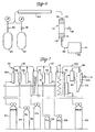
- the arrangement of the tubes 39 can be better understood by referring to FIGS. 2 and 3 in addition to FIG. 1.
- the plurality of tubes 39 which form the grid 36 are parallel to each other with their longitudinal axes transverse to the direction of flow of the flue gas.
- Each tube 39 has a plurality of holes 40 along its length which act as nozzles for the vaporized propane.
- the holes are aligned so that the direction of flow of heated propane is about 10 to 20° from an imaginary plane passing through the array.
- the heated propane to be introduced into the flue gas stream without impinging on adjacent distributor tubes, thereby reducing tube soot formation and promoting nozzle cleanliness.
- the heated propane is introduced in the direction of flue gas flow as shown.
- the tubes do not become coated with soot from the propane oxidation reactions.
- FIG. 4 there is shown a semi-schematic cross-sectional view of an exemplary embodiment of a premixer/preheater 35 useful in practice of this invention.
- the illustrated premixer/preheater is a modification of the type sold by John B. Zink Co. and identified as model TH-210.
- Propane (or other such peroxyl initiator) is introduced into the premixer/preheater through a main gas connection 45.
- Air, oxygen or recirculated flue gas or mixtures thereof are introduced at the inlet 42.
- the air/propane mixture which, in accordance with this invention is provided with oxygen in excess of the stoichiometric amount required to burn the propane, is ignited at a burner gas tip 44, for example, by means of a pilot 46.
- the combustion gas formed by the burning propane exits the end of a shroud 48 and mixes with propane that is introduced into the premixer/preheater via the connections 50.
- the propane is heated to between ambient temperature and about 426,7°C (800°F)).
- the heated vaporized propane and excess oxygen flows from the premixer/preheater through the pipe 38 into the distributor pipes 39 of the grid 36. From the grid 36 the injection gas is introduced into the rear cavity conduit 20 just upstream from the boiler convective section 22.
- the injection gas is introduced in a sufficient quantity and at a sufficient velocity to provide a barrier or blanket of such gas that extends across essentially the entire rear cavity (conduit) 20 cross-section transverse to the direction of flow of the NO containing flue gas stream.
- the NO containing gas stream contacts the injection gas (the vaporized peroxyl initiator and oxygen) as it (the NO containing gas) flows through the conduit.
- the NO in the flue gas contacts the vaporized injection gas mixture, the NO is converted to NO2 in accordance with the above reactions I and II.
- propane is used as the peroxyl initiator.
- the temperature of the heated propane/oxygen mixture (the injection gas) at the time of injection into the flue gas stream is preferably less than about 426,7°C (800°F).
- the peroxyl radicals can form before the injection gas is introduced into the flue gas stream. Since the life of the peroxyl radical is less than about 40 milliseconds, such radicals formed prior to introduction into the flue gas, may be extinguished and thus, not available for the conversion reaction. Therefore, it is not preferred that the propane (injection gas) be heated to greater than about 426,7°C(800°F) in the premixer/preheater 35 or in the injection grid 36.
- the O2 concentration of the injection gas is from about 5% to about 20% by volume O2. At less than about 5% there is insufficient O2 to cause a desirably high conversion of NO to NO2 when the boiler flue gas also contains low levels of O2, typically less than 5%. Alternatively, it is not economical or necessary to provide O2 at greater than about 20%.
- An important feature of this invention is that the oxygen concentration provided at the reaction site (the site of conversion of NO to NO2) by means of the high oxygen content injection gas is sufficient to promote such conversion. This provision of sufficient oxygen is accomplished without requiring levels of excess O2 as high as 9% (or more) in the boiler flue gas, and hence without increasing the size of the boiler.
- the NO containing gas stream is at a temperature of from about 426,7°C (800°F) to about 760°C (1400°F) at the time of contact with the injection gas. At less than 426,7°C(800°F), the temperature is not sufficiently high to generate the required peroxyl radicals. Thus, little if any conversion takes place.
- the flue gas temperature is greater than about 760°C(1400°F).
- different hydrocarbon radicals predominate and the effect is to cause NO to be reduced to nitrogen gas, rather than to be oxidized to NO2.
- the NO containing flue gas stream has a velocity of from about 9,14 meters/second (30 feet per second) to about 21,33 meters/second (70 feet per second).
- the injection gas is sprayed into the conduit 20 across the path of the NO containing gas stream at a velocity at least about 10 times higher than the velocity of the NO containing flue gas stream.
- This high velocity for the injection gas is required, in part, so that a blanket or barrier of such injection gas is across the entire flue gas flow path.
- all of the flue gas must pass through and contact the injection gas as it travels through the boiler convective section.
- an NO containing flue gas stream entering the rear cavity 20 is at 648,9°C (1200°F) and is provided at a volumetric flow rate of 5,569 liters/second (11,800 cubic feet per minute (CFM)) at a velocity of 9,14 meters/second (30 feet per second).
- An injection gas at less than 426,7°C (800°F) is provided at 307 liters/second (650 (CFM)) and is introduced through the distributor tubes 39, which, in this embodiment, have a total of 168 injection holes with each hole being about 0,475 cm (0.187 inches) in diameter.
- the velocity of the injection gas in this embodiment is about 182,8 meters/second (600 feet per second).
- the injection gas provides a blanket across the entire cross section of the rear cavity 20 of the boiler. All flue gas passing from the burner section 12 into the boiler convective section 22 passes through the injection gas blanket. The contact of the NO containing flue gas with the injection gas results in conversion of NO in the flue gas to NO2.
- peroxyl initiator includes hydrocarbons, i.e., compounds that consist of only carbon and hydrogen, compounds that include carbon, hydrogen and oxygen (oxygen substituted hydrocarbons), and materials that contain only hydrogen and oxygen such as hydrogen peroxide. Hydrogen gas can also be used.
- peroxyl initiators useful in practice of principles of this invention include, but are not limited to, propane, benzene, ethane, ethylene, n-butane, n-octane, methane, hydrogen, methanol, isobutane, pentane, acetylene, methyl alcohol, ethyl alcohol, acetone, glacial acetic acid, ethyl ether, propyl alcohol, nitrobenzyl alcohol, methylethylketone, propylene, toluene, formaldelyde, camphor, ether and glycol and mixtures thereof. Additionally, as it is mentioned above, hydrogen peroxide and hydrogen gas can be used.
- peroxyl initiators which include oxygen, for example, methanol, hydrogen peroxide, etc., or ether, either alone or in combination with hydrocarbons such as propane, will provide an additional source of oxygen which should facilitate the NO to NO2 conversion at low levels of excess O2 in boiler flue gas.
- FIG. 5 there is shown a schematic view of a boiler 51 used in the tests of this example.
- the boiler 51 is a 98 kJoule/second (10 horse power (H.P.)) firetube boiler manufactured by McKenna Boiler Works of Los Angeles, California.
- the heating surface is 5,95 square meters (64 square feet), with 862 kPa gauge (125 psig) steam pressure rating.
- the burner is gas fired with a spark igniter.
- a stainless steel injection probe 52 extends into the boiler convective passage 54.
- the probe has 18 radial injection gas holes 56 through its walls (only six such holes are illustrated).
- the probe air supply was provided by air compressor (not shown), rated to provide over 7,3 standard liters/second (7 SCFM) at 138 kPa gauge (20 psig).
- the probe injection pressure for these tests was 34,5 kPa Gauge (5.0 psig).
- the gas injection temperature was about 121,1° C (250°F) at the end of the probe, as measured by a thermocouple (not shown) on the inside of the probe.
- the calculated gas flowrate at 34,5 kPa gauge (5.0 psig) is about 2.5 standard liters/second (5.3 SCFM), amounting to between 4 % and 8 % of the total flue gas flowrate, depending on firing conditions.
- NO gas was injected through a port 57 into a burner 58 at the discharge of a fan 60.
- the NO and propane injection rates were controlled by rotameters (not shown).
- Flue gas samples were continously withdrawn from a sample port 61 on a boiler stack 62 at a rate of about 70,8 standard liters/hour (2.5 SCFH).
- the gas samples were passed through an NO-NO x analyzer and an oxygen detector for excess O2 measurement.
- the flue gas flowrate was calculated by two methods. The first method was based on the known rate of NO addition and measured concentration of NO x in the stack gas. This method predicts flue gas flowrates which are lower than actual, due to the NO destruction which occurs in the flame. The second method was based on the measured increase in flue gas excess oxygen content caused by addition of a known rate of ambient air addition through the injection probe. The rate of NO addition was not varied during the tests.
- the flue gas flowrate was calculated to be 29,4 standard liters/second (62.2 SCFM) (3 % O2, dry), equivalent to 117,150 joules/second (400,000 BTU/hr) firing rate.
- the firing rate was reduced to about 60 % of maximum, which resulted in an increase in the excess O2 content , as would normally be expected.
- the excess O2 at 3.4 % approximately 1900 ppm of propane was injected into the flue gas,along with about 2,60 standard liters/second (5.5 SCFM) of ambient air. This resulted in converting 71 % of the NO into NO2 at a gas temperature of 665,6°C (1230°F).
- the amount of propane used about 5.4 % of the total fuel used.
- the excess O2 content of the flue gas was increased to 4.2 %.
- the flue gas with reduced levels of NO and increased levels of NO2 passes from the convective section of the boiler 10 (the NO to NO2 conversion section), through an air preheater section 24 and then into the absorption section 25 of the system. (Since the conversion of NO to NO2 takes place in the area of the boiler between the grid 36 and the topmost tubes 23 in the convection section 22, this space is termed the “conversion section" herein).
- the absorption section of the system includes means for receiving the gas stream as it exits the NO to NO2 conversion section and means for introducing a substantially dry particulate sorbent into the gas stream for sorbing oxides of sulfur and nitrogen therefrom to provide a reacted sorbent. Means are also provided for removing the reacted sorbent and any unreacted sorbent from the gas stream to provide a clean waste gas stream which can be discharged into the atmosphere.
- a dry particulate sodium based sorbent such as Trona® or Nahcolite is introduced into the gas stream at the entrance to the baghouse 26 (Trona® is Na2CO3 NaHCO3 2H2O whereas Nahcolite is NaHCO3.)
- the fresh sorbent is stored in one or more hoppers 64 and is fed through a rotary lock valve 66 located below the hopper 64 into an air stream provided by a blower 68.
- Some of the partially-reacted sorbent from the baghouse hoppers 69 is recycled via rotary lock valves 67 located below hoppers 69 into an air stream provided by the blower 68.
- the sorbent transport media can be steam or flue gas or the like or mixtures of steam and flue gas with air).
- the air stream and entrained sorbent passes through a plurality of holes or nozzles (not shown) in an array of tubes 70 that extend into the flue gas flow path near the entrance to the baghouse.
- a flue gas and sorbent distribution manifold or ducts 27 with discrete discharge ports 29, to promote uniform distribution of flue gas and sorbent materials on the baghouse filtration surfaces.
- the particulate sorbent reacts with the NO x and oxides of sulfur (SO x ) in the flue gas to remove SO x and NO x from the flue gas.
- SO x oxides of sulfur
- the average particle size of the sorbent used is preferably less than about 60 ⁇ m to enhance gas-solid distribution in the gas stream which, in turn, promotes more uniform distribution of solids on the baghouse filtration surfaces, resulting in more effective absorption of the SO x and NO x from the gas.
- the flue gas and particulate sorbent enters the baghouse where the gas passes through the filtration surfaces 28 and is discharged as clean flue gas through the conduit 30, to the stack and thence into the atmosphere.
- the nozzles 29 extending from the manifold 27 direct the flue gas upwardly into the baghouse filtration surfaces.
- the particulate sorbent is filtered from the flue gas by the filtration surfaces supported on the bags.
- the particulate sorbent, plus any noncombustible ash from the fuel is dislodged and falls into the discharge hoppers 69 and is either discarded or recycled for further use.
- the recycle ratio can be adjusted by suitable connection of rotary lock valves and transport pipes (not shown).
- Nitric oxide (NO) is also sorbed on NaHCO3 material or Trona material in the presence of SO2, forming NaNO2 byproduct in a reaction similar to reaction VI.
- the NaNO2 byproduct can be oxidized to NaNO3 while in contact with flue gas.
- a metal oxide absorption section is used for NO x removal in general and NO2 removal in particular.
- the metal oxide can be easily regenerated by heating to over 371,1°C(700°F) which produces an off-gas stream containing nitric oxide (NO). This off-gas stream can be recycled to the main burners on the boiler, where most of the extra nitric oxide (NO) is destroyed in the flame zone.
- the particulate sorbent comprises a mixture of about 15% NaHCO3 and 85% Ca(OH)2 by weight. (Preferably, the sorbent comprises at least about 5% NaHCO3, Na2CO3 or mixtures thereof).
- the absorbent may be introduced into the gas stream in a spray dryer with the outlet of the spray dryer discharging into the baghouse.
- the absorption zone comprises two sections.
- a first section of the absorption zone the flue gas stream exiting the NO to NO2 conversion zone (the second gas stream) is contacted with a particulate sorbent for oxides of nitrogen and sulfur to thereby remove oxides of nitrogen and sulfur from the gas stream forming a third gas stream.
- the third gas stream is then passed into a second section of the absorption zone wherein the third gas stream and particulate sorbent contact a liquid sorbent for NO2 and sulfur oxides.
- the liquid sorbent removes NO2 and sulfur oxides not removed by the particulate sorbent and also removes the particulate sorbent.
- the molar ratio of SO2/NO x has an effect on the amount of removal of NO x from the flue gas by particulate sorbents such as those used in practice of this invention.
- the SO2/NO x ratio is greater than about 3 and more preferably the ratio is greater than about 5.
- the ratio of SO2 to NO x can be as high as 30/1 and when low sulfur fuel is burned the SO2/NO x ratio can be as low as 1/1.
- the ratio can be maintained in the preferred range for the dry sorbent being used.
- the flue gas with reduced levels of NO and increased levels of NO2 passes from the conversion section of the boiler to a conventional wet scrubber.
- the wet scrubber comprises a liquid sorbent or sorbents for SO2 removal, e.g., an alkali such as Ca(OH)2 or CaCO3, with the addition of NaOH or Na2CO3 for enhanced NO2 removal.
- the alkali contains at least 5% by weight sodium compounds.
- the SO2 and NO2 are removed via the scrubber and the clean flue gas is discharged to the atmosphere. Removal of NO x in this embodiment can be increased using EDTA or other well-known additives such as ferrous sulfate or ferrous chelate in the scrubbing liquid.
- a heated stainless steel reactor tube 70 was packed with fiberglass plugs 72 and 74 at the top and bottom ends respectively. Pipe caps 76 and 78 were screwed into the top and bottom ends of the reactor to hold the fiberglass plugs in place.
- Separate compressed gas cylinders 80 and 82 containing NO2 (plus dry air) and SO2 (plus dry air) respectively were connected to the top of the reactor 70 via an electrically heated sample line 84.
- the sample line 84 entered the top of the reactor 70 through a hole in the pipe cap 76.
- a port 86 was provided for injecting dry particulate Trona and/or Nahcolite into the reactor.
- a line 88 was connected between the bottom (outlet) of the reactor and a NO x /SO x gas analyzer 89.
- the composition of the Nahcolite used during these tests was at least about 93% NaHCO3, between about 1 and 3% Na2CO3 about 0.5% NaCl with the balance moisture.
- the composition of Trona used was from about 33-37% Na2CO3, 22-27% NaHCO3, 4-8% NaCl, 5-7% Na2SO4, 6-10% water insolubles and 12-21% total H2O.
- the tests were conducted by heating the reactor and sample lines to a desired temperature. Then, after the NO x /SO x gas analyzer had been calibrated, valves 90 and 91 on the outlets of the cylinders 80 and 82 were opened to provide a desired flow rate of NO2 and SO2 through the apparatus.
- the cylinders 80 and 82 contained NO2 and SO2 in trace amounts mixed with dry air as a carrier gas. The parts per million (ppm) of SO2 and NO2 entering the inlet of the reactor vessel were recorded. Dry sorbent was then injected into the reactor via the injection port 86. The ppm of SO2 and NO2 exiting the reactor were measured and the percentages of NO2 and SO2 which were removed were recorded.
- the test apparatus 92 used in the second series of experiments included compressed gas cylinders 93, 94, 96, 98, 100 and 102 containing argon, O2, CO2, SO2, NO2 and argon respectively.
- Argon (cylinder 93), O2 and CO2 were initially metered via calibrated rotameters 104, 106 and 108 respectively, into a common manifold line 110, through a water column 111 and into the line 112.
- the SO2 and NO2 test gases at concentrations (in Argon carrier gas) of about fifteen thousand ppm and five thousand ppm respectively were introduced into the line 112 through rotameters 113 and 114.
- the mixture of test gases was then passed (in a tube 115) through an oil bath 116 which was maintained at a temperature which could be adjusted to between 148,9°C (300°F) and 204,4°C (400°F).
- a tee 118 was in the sample line 120 at the outlet of the oil bath to allow sorbent from a fluidized bed sorbent feeder 121 into the sample line upstream from a filter housing 122.
- the filter housing 122 included a 15,24 cm (6- inch) diameter filter 124 which was precoated with diatomaceous earth or highly pulverized calcium sulfate powder so that the pressure drop across the filter could be maintained at about 747PA (3 inches of water) during the tests.
- the filter housing 122 was insultated and heated to allow adjustment of the gas temperature inside the filter. During the course of the tests,NaHCO3 powder was deposited on the filter leaving a partially-reacted sorbent cake at the end of the run. Each run lasted about 15 to 30 minutes.
- the temperature of the inlet gases introduced into the filter housing was adjusted by changing the power input to the heat tape (not shown) located between the stainless steel filter housing shell and an outer layer of insulation (not shown) which surrounded the filter housing.
- the filter housing temperature was measured with a thermocouple probe (not shown) placed in the inlet gas stream about 1 inch above the filter.
- FIG. 8 shows that overall NO x removal with dry test gases fell somewhere between about 50% and 70% when the filter housing gas temperatures were in the range of from about 182,2°C (360°F) to 204,4°C (400°F).
- FIG. 9 shows that at temperatures in the temperature range of from about 171,1°C (340°F) to 204,4°C (400°F), between about 60 % and 90 % of the inlet NO2 is eliminated in the process as described above.
- the desired temperature of the gas stream as it is contacted by the particulate sorbent for removal of NOx and SOx is between about 93,3°C (200°F) and 232,2°C (450°F).
- the temperature is between about 148,9°C (300°F) and 204,4°C (400°F) when Nahcolite sorbent is used.
- the amount of NaHCO3 sorbent used can also be important.
- the stoichiometric ratio of sorbent to SO x is greater than 1 and more preferably is greater than 4.
- the percent removal of both SO x and NO x using NaHCO3 sorbent increases with an increasing sorbent stoichiometric ratio.
- the inlet NO x consisted of at least 75% NO2. As is seen in Table VII, the NO x removal was negligible when the inlet SO2/NO x ratio was reduced to zero. This shows that the presence of SO2 is required for NO x sorption on a sodium-based alkali such as Nahcolite.
- NO2 is known to be sorbed on oxides of the following metals, or alloys of the following metals including: aluminum, zirconium, nickel, iron, copper, magnesium, titanium and the like.
- the metal oxide can be provided on a suitable supporting substrate to preferably provide a metal oxide specific surface area of greater than about ten square meters per gram of total sorbent material.
- NO2 is sorbed primarily as a surface nitrate having a nitrato bidentate attachment to the surface. NO is also sorbed, but not nearly as easily as NO2.
- FIG. 11 a schematic perspective view of a NO x sorption system 130 which can be installed in accordance with practice of this invention, for example, in the duct 30 from the baghouse 26 is shown.
- the sorbent-free flue gas which exits the baghouse in the duct 30, (see FIG. 1) passes through a bed 132 of metal oxide pebbles or pellets having a high specific surface area for the metal oxide 133.
- a flue gas velocity of 12,19 meters/second (40 feet/second) across a bed 1,22 m (4 feet) thick provides a 0.1 sec. residence time, and results in a gas-side pressure drop of less than about 249 Pa (1.0 in. H2O).
- the pellets 133 move slowly downwardly in the bed 132 and are eventually discharged from the bed into a hopper 134 located, for example, below the flue gas duct 30.
- the pellets which have NO x sorbed thereon and have been discharged into the hopper 134 are regenerated by driving the NO x from the pellets in the form of NO. This is accomplished, for example, in a fluidized bed 138.
- the pellets pass from the hopper 134 through a rotary lock valve 136 into the fluidized bed. As the pellets are heated in the fluidized bed, NO is driven from the pellets.
- the NO containing off gas from the fluidized bed is recycled at a high temperature, e.g., about 398,9°C(750°F) through the line 139 back to the burners 12 (shown in FIG. 1 ) of the boiler 10. Since the total NO produced in the boiler is in thermodynamic equilibrium, most of the extra NO introduced by the metal oxide regeneration system is destroyed in the main burner flame. Waste heat from the hot regenerated pellets can be recaptured by counterflow heat exchange against the ambient air being supplied to the burner system for the fluidized bed, if desired.
- Cooled, regenerated metal oxide pellets can be pneumatically conveyed to the top of the pellet bed duct, for example, by means of a conveyor system 140 which includes a blower 142, a cyclone 144 and a conveying line 146 between the blower and cyclone.
- the regenerated metal oxide pellets pass from the fluidized bed by means of a rotary valve 148 into the line 146 and are conveyed into the cyclone 144 at the top of the bed 132.
- the pellets pass from the cyclone back into the bed through a rotary lock valve 150 at the top of the bed. Fines can be recovered from the top of cyclone by means of the line 152 connected to a filter 153 by a suitable duct (not shown).
- Example I the same boiler that was used for Example I was also used in the experiments of this example.
- a 6,1 meters (20 foot) length of 0,635 cm (0.25 in. ) O.D. oxidized aluminium tubing 160 was connected to the offgas stack 62 at the connection 61.
- sample gas Approximately 70,8 standard liters/hour (2.5 SCFH) of sample gas was withdrawn through the tubing to thereby contact its AL2O3 inner surface.
- the calculated inside volume of the tubing was 108 cm3 (6.6 in.3), giving a flue gas residence time of about 90 milliseconds.
- the inside surface area of the tubing was 903 cm2 (140 in.2).
- Short-duration screening tests were carried out to determine the effects of the Al2O3 on NO and NO2 removal, and also to verify that the Al2O3 could be regenerated upon heating by driving off NO x in the form of nitric oxide (NO) gas.
- NO nitric oxide
- NO gas was injected into the burner 58 at the discharge of the fan 60.
- the NO injection rate was controlled by a rotameter (not shown).
- Flue gas samples were continuously withdrawn from the boiler stock 62 through the Al2O3 tubinq 160 at a rate of about 70,8 standard liters/hour (2.5 SCFH) and passed through two series impingers in a ice bath to remove excess moisture (not shown). The gas sample was then passed through a NO-NO x analyzer and through a portable oxygen detector for excess O2 measurement.
- Example I The same boiler that was used for Example I was also used in the experiments of this example, except that a pulsejet baghouse, manufactured by EVO Corporation, Model NF-9, was placed downstream from the boiler.
- the baghouse incorporates eight bags having a total of 40 square feet of filtration surfaces.
- the filtration material was felted Nomex cloth.
- the baghouse was supplied with a variable-speed I.D. fan used to overcome the pressure drop through the bags and to balance the draft requirements of the boiler. In this example the pressure drop across the bags was approximately 3 inches of water and the air to cloth ratio was about 15,75 absolute liters/s/m2(3.1 ACFM/ft
- the practice of the present invention provides surprisingly higher levels of NO x removal, in combination with SO2 removal.
- Table X With upstream NO to NO2 conversion, approximately 46% NO x removal was obtained at a lower stoichiometric ratio of about 2, also resulting in a lower SO2 removal of 94%.
- This improvement in NO x removal also occurred with a lower level of initial SO2/NO x ratio, which further demonstrates the usefulness of the present invention.
- the amount of NO2 increased by 36 ppm (as compared with the previous result of 47 ppm), showing that the amount of NO2 resulting from simultaneous removal of SO2 and NO x was reduced.
- the present invention provides a process for removing this NO2 byproduct using a downstream metal oxide absorption section.
- regenerable metal oxides such as those described above can be introduced in powder form into the absorption zone for contacting a flue gas stream that contains oxides of nitrogen such as NO2.
- the metal oxide removes the oxides of nitrogen from the gas stream and is separated from the gas stream for example, in a baghouse.
- the metal oxide can then be regenerated for reuse by heating it to a least about 371,1°C (700°F). Such heating produces an off-gas containing NO which can be recycled to the burner section of the boiler.
Abstract
Claims (25)
- Procédé pour convertir le NO en NO₂ dans des gaz d'échappement de combustion, lequel procédé comprend la mise en contact, dans une section de mise en contact de gaz en aval de la chambre de combustion, d'un courant de gaz d'échappement contenant du NO avec un fluide d'injection, caractérisé en ce que le fluide d'injection comprend des quantités prémélangées d'un initiateur de peroxyle avec suffisamment d'oxygène pour assurer la conversion du NO en NO₂, l'action de prémélange étant exécutée à l'extérieur de la section de mise en contact de gaz.
- Procédé suivant la revendication 1, caractérisé en ce que le fluide d'injection contient au moins 5% en volume d'oxygène, sur la base du volume total du fluide d'injection.
- Procédé suivant la revendication 2, caractérisé en ce que le fluide d'injection contient d'environ 5% à environ 20% en volume d'oxygène, sur la base du volume total du fluide d'injection.
- Procédé suivant l'une quelconque des revendications précédentes, caractérisé en ce que la teneur en oxygène du courant de gaz d'échappement de combustion n'est pas augmentée de plus de 1% de sa valeur initiale après le mélange avec le fluide d'injection.
- Procédé suivant l'une quelconque des revendications précédentes, caractérisé en ce qu'il comprend :a) le passage d'un courant de gaz d'échappement de combustion contenant des oxydes d'azote, y compris du NO, par un conduit;b) l'introduction du fluide d'injection dans le conduit en une quantité suffisante par un nombre suffisant d'endroits d'injection et à une vitesse suffisante pour assurer que le fluide d'injection parvienne dans sensiblement toute la section transversale du conduit dans un plan sensiblement transversal à la direction d'écoulement du courant de gaz contenant du NO, le courant de gaz contenant du NO venant ainsi en contact avec le fluide d'injection à mesure que le courant de gaz contenant du NO s'écoule par le conduit.
- Procédé suivant la revendication 5, caractérisé en ce que le fluide d'injection est introduit dans une chaudière classique en un ou plusieurs endroits dans la section de convection ou les régions de cavité arrière pour venir en contact avec le gaz contenant du NO.
- Procédé suivant l'une quelconque des revendications 5 et 6, caractérisé en ce que le fluide d'injection est introduit dans le conduit par une pluralité de becs où la vitesse de sortie du fluide d'injection de chaque bec est au moins 10 fois supérieure à la vitesse du courant de gaz contenant du NO au voisinage des becs.
- Procédé suivant l'une quelconque des revendications précédentes, caractérisé en ce que le fluide d'injection est préchauffé à une température d'injection de moins d'environ 427°C (800°F).
- Procédé suivant l'une quelconque des revendications précédentes, caractérisé en ce que le courant de gaz d'échappement de combustion se trouve à une température de plus d'environ 427°C (800°F) au moment du contact avec le fluide d'injection.
- Procédé suivant la revendication 9, caractérisé en ce que le courant de gaz d'échappement de combustion se trouve à une température d'environ 427°C (800°F) à environ 760°C (1400°F) au moment du contact avec le fluide d'injection.
- Procédé suivant l'une quelconque des revendications précédentes, caractérisé en ce que le courant de gaz d'échappement de combustion entrant dans la section de mise en contact de gaz présente un rapport molaire du NO au NO₂ de plus d'environ 4 et le courant de gaz quittant la section de mise en contact de gaz présente un rapport molaire du NO au NO₂ de moins d'environ 2.
- Procédé suivant l'une quelconque des revendications précédentes, caractérisé en ce que l'initiateur de peroxyle est choisi dans la classe formée par les hydrocarbures, les hydrocarbures substitués par l'oxygène, l'hydrogène et le peroxyde d'hydrogène, outre leurs mélanges.
- Procédé suivant la revendication 12, caractérisé en ce que l'initiateur de peroxyle est le méthanol.
- Procédé suivant la revendication 12, caractérisé en ce que l'initiateur de peroxyle est choisi dans la classe formée par le méthane, l'éthane, les gaz hydrocarbonés et leurs mélanges.
- Procédé suivant la revendication 14, caractérisé en ce que l'initiateur de peroxyle combustible est brûlé et mélangé avec un supplément d'air ou d'oxygène pour former un fluide d'injection prémélangé préchauffé.
- Procédé pour éliminer les oxydes d'azote et de soufre d'un courant de gaz d'échappement de combustion, comprenant les stades :a) de conversion du NO en NO₂ dans le gaz d'échappement de combustion dans une zone de conversion;b) de passage du courant de gaz résultant dans une zone d'absorption pour élimination du SO₂ où le NO₂ est aussi éliminé;
caractérisé en ce que le stade a) est exécuté par un procédé suivant l'une quelconque des revendications précédentes. - Procédé suivant la revendication 16, caractérisé en ce que la zone d'absorption comprend un laveur humide.
- Procédé suivant la revendication 17, caractérisé en ce que les réactants chaux ou calcaire sont utilisés dans le laveur humide pour l'élimination du SO₂ et du NO₂.
- Procédé suivant la revendication 17, caractérisé en ce que des réactants alcalins à base de sodium, comme NaOH ou Na₂CO₃, sont utilisés dans le laveur humide pour l'élimination du SO₂ et du NO₂.
- Procédé suivant l'une quelconque des revendications 17 à 19, caractérisé en ce que des additifs choisis dans la classe formée par l'EDTA, le sulfate ferreux, un chélate ferreux et leurs mélanges sont utilisés dans le liquide de lavage pour améliorer l'élimination du NOx par le laveur humide.
- Procédé suivant la revendication 16, caractérisé en ce que la zone d'absorption comprend une matière sorbante particulaire.
- Procédé suivant la revendication 21, caractérisé en ce que le procédé de mise en contact du courant de gaz résultant avec la matière sorbante particulaire comprend le stade d'injection de la matière sorbante particulaire dans le gaz de combustion à l'amont d'un filtre à manches au moyen d'un séchoir par pulvérisation ou d'un appareil d'alimentation pneumatique et de recyclage d'une partie de la matière sorbante collectée dans le filtre à manches.
- Procédé suivant l'une quelconque des revendications 21 et 22, caractérisé en ce que la matière sorbante particulaire est choisie dans la classe formée par le trona, la nahcolithe, la chaux, la chaux hydratée, la chaux enrichie en sodium, les cendres volantes, leurs dispersions utilisables dans les séchoirs par pulvérisation ou leurs combinaisons comprenant de l'eau d'hydratation.
- Procédé suivant l'une quelconque des revendications 21 à 23, caractérisé en ce que la sorption du NO₂ est améliorée à l'aide d'un ou plusieurs oxydes métalliques appropriés ajoutés.
- Procédé suivant l'une quelconque des revendications 21 à 24, caractérisé en ce que le rapport molaire du SO₂ au NOx dans le courant de gaz résultant à l'amont de la zone d'absorption est supérieur à environ 3.
Priority Applications (1)
| Application Number | Priority Date | Filing Date | Title |
|---|---|---|---|
| AT85903110T ATE79834T1 (de) | 1985-05-14 | 1985-06-03 | Verfahren zur beseitigung der stickstoffoxyde und des schwefels aus abgasen. |
Applications Claiming Priority (3)
| Application Number | Priority Date | Filing Date | Title |
|---|---|---|---|
| US06/734,393 US4783325A (en) | 1985-05-14 | 1985-05-14 | Process and apparatus for removing oxides of nitrogen and sulfur from combustion gases |
| US734393 | 1985-05-14 | ||
| CA000522496A CA1330252C (fr) | 1985-05-14 | 1986-11-07 | Procede et appareillage pour eliminer les oxydes d'azote et de soufre des gaz de combustion |
Publications (3)
| Publication Number | Publication Date |
|---|---|
| EP0221899A1 EP0221899A1 (fr) | 1987-05-20 |
| EP0221899A4 EP0221899A4 (fr) | 1989-01-12 |
| EP0221899B1 true EP0221899B1 (fr) | 1992-08-26 |
Family
ID=25671153
Family Applications (1)
| Application Number | Title | Priority Date | Filing Date |
|---|---|---|---|
| EP85903110A Expired - Lifetime EP0221899B1 (fr) | 1985-05-14 | 1985-06-03 | Procede d'extraction d'oxydes d'azote et de soufre contenus dans des gaz de combustion |
Country Status (6)
| Country | Link |
|---|---|
| US (2) | US4783325A (fr) |
| EP (1) | EP0221899B1 (fr) |
| JP (1) | JPS63500166A (fr) |
| AU (1) | AU588533B2 (fr) |
| CA (1) | CA1330252C (fr) |
| WO (1) | WO1986006711A1 (fr) |
Families Citing this family (41)
| Publication number | Priority date | Publication date | Assignee | Title |
|---|---|---|---|---|
| US4925633A (en) * | 1988-07-25 | 1990-05-15 | The Babcock & Wilcox Company | Combined catalytic baghouse and heat pipe air heater |
| US5047219A (en) * | 1989-08-18 | 1991-09-10 | Fuel Tech, Inc. | Hybrid process for nitrogen oxides reduction |
| US5133950A (en) * | 1990-04-17 | 1992-07-28 | A. Ahlstrom Corporation | Reducing N2 O emissions when burning nitrogen-containing fuels in fluidized bed reactors |
| US5637198A (en) * | 1990-07-19 | 1997-06-10 | Thermo Power Corporation | Volatile organic compound and chlorinated volatile organic compound reduction methods and high efficiency apparatus |
| US5458748A (en) * | 1990-07-19 | 1995-10-17 | Thermo Power Corporation | Coronal-catalytic apparatus and method for NOx reduction |
| DK180190D0 (da) * | 1990-07-27 | 1990-07-27 | Aalborg Boilers | Fremgangsmaade og anlaeg til nedsaettelse af indholdet af nitrogenoxider i roeggas |
| JPH04243525A (ja) * | 1991-01-22 | 1992-08-31 | Toyota Motor Corp | 内燃機関の排気浄化装置 |
| US5443805A (en) * | 1991-08-21 | 1995-08-22 | Massachusetts Institute Of Technology | Reduction of combustion effluent pollutants |
| FR2681795B1 (fr) * | 1991-09-30 | 1993-11-19 | Solvay | Procede pour epurer un gaz contenant de l'oxyde nitrique et du dioxyde de soufre. |
| DE59301406D1 (de) * | 1992-09-30 | 1996-02-22 | Siemens Ag | Verfahren zum Betreiben einer Kraftwerksanlage sowie danach arbeitende Anlage |
| US5538703A (en) * | 1993-10-29 | 1996-07-23 | Massachusetts Institute Of Technology | Hot gas desulfurization by injection of regenerable sorbents in gasifier-exit ducts |
| US5462718A (en) * | 1994-06-13 | 1995-10-31 | Foster Wheeler Energy Corporation | System for decreasing NOx emissions from a fluidized bed reactor |
| FR2724328B1 (fr) * | 1994-09-09 | 1997-01-10 | Solvay | Composition reactive et procede pour l'epuration d'un gaz contenant de l'oxyde nitrique |
| US5670122A (en) * | 1994-09-23 | 1997-09-23 | Energy And Environmental Research Corporation | Methods for removing air pollutants from combustion flue gas |
| US6481998B2 (en) * | 1995-06-07 | 2002-11-19 | Ge Energy And Environmental Research Corporation | High velocity reburn fuel injector |
| US6206949B1 (en) * | 1997-10-29 | 2001-03-27 | Praxair Technology, Inc. | NOx reduction using coal based reburning |
| AU2856300A (en) * | 1999-01-21 | 2000-08-07 | Tiberian Industries, Inc. | A method and apparatus for oxidation of nitric oxide using irradiated oxidizing compounds |
| US6676912B1 (en) | 1999-10-28 | 2004-01-13 | The United States Of America As Represented By The Administrator Of The National Aeronautics & Space Administration | Method for removal of nitrogen oxides from stationary combustion sources |
| US6793903B1 (en) * | 2001-03-08 | 2004-09-21 | The United States Of America As Represented By The Administrator Of The National Aeronautics And Space Administration | High temperature decomposition of hydrogen peroxide |
| JP4012011B2 (ja) * | 2002-08-27 | 2007-11-21 | 独立行政法人科学技術振興機構 | 被処理ガス中にNO2を共存させてSO2をCaSO4として回収する脱硫方法および脱硫装置 |
| US7790128B2 (en) * | 2003-04-04 | 2010-09-07 | United States Of America As Represented By The Administrator Of The National Aeronautics And Space Administration | Hydrogen peroxide catalytic decomposition |
| US20050201914A1 (en) * | 2004-03-12 | 2005-09-15 | American Electric Power Company, Inc. | System and method for treating a flue gas stream |
| US7531154B2 (en) | 2005-08-18 | 2009-05-12 | Solvay Chemicals | Method of removing sulfur dioxide from a flue gas stream |
| BRPI0616068A2 (pt) * | 2005-09-15 | 2011-06-07 | Solvay Chemicals Inc | métodos de remoção de so3 de uma corrente de gás de combustão, e de fornecimento de um sorvente seco para injeção de gás de combustão |
| US7481987B2 (en) | 2005-09-15 | 2009-01-27 | Solvay Chemicals | Method of removing sulfur trioxide from a flue gas stream |
| US7964170B2 (en) * | 2007-10-19 | 2011-06-21 | Fluegen, Inc. | Method and apparatus for the removal of carbon dioxide from a gas stream |
| US20100074828A1 (en) * | 2008-01-28 | 2010-03-25 | Fluegen, Inc. | Method and Apparatus for the Removal of Carbon Dioxide from a Gas Stream |
| FR2937888B1 (fr) * | 2008-10-31 | 2011-08-19 | Solvay | Dispositif et procede pour distribuer un fluide. |
| CA2760777C (fr) * | 2009-05-15 | 2017-09-05 | Fmc Corporation | Traitement des nox presents dans les gaz de carneau |
| FR2945961B1 (fr) * | 2009-05-29 | 2012-07-13 | Air Liquide | Epuration d'un gaz contenant des oxydes d'azote |
| US20110014106A1 (en) * | 2009-07-15 | 2011-01-20 | Fmc Corporation | COMBUSTION FLUE GAS SOx TREATMENT VIA DRY SORBENT INJECTION |
| CN102741157B (zh) | 2009-08-03 | 2016-01-20 | Fmc有限公司 | 用催化剂对活性化合物进行活化 |
| US8795621B2 (en) * | 2012-08-09 | 2014-08-05 | Exxonmobil Research And Engineering | Catalytic reduction of NOx with high activity catalysts with acetaldehyde reductant |
| CA2924319C (fr) | 2013-09-13 | 2021-06-22 | Peroxychem Llc | Traitement des oxydes d'azote dans les flux de gaz de combustion |
| US10343111B2 (en) | 2014-11-13 | 2019-07-09 | Spartan Energy Services LLC | Desulfurization of flue gas from an amine process |
| US9764281B2 (en) * | 2015-12-18 | 2017-09-19 | Cannon Technology, Inc. | Process for the removal of contaminants from flue gas streams |
| US10946335B2 (en) * | 2017-07-20 | 2021-03-16 | Ariel Scientific Innovations Ltd. | Catalytic oxidation of NOx/SOx in flue gases with atmospheric oxygen as the oxidation reagent |
| WO2019048017A1 (fr) * | 2017-09-07 | 2019-03-14 | Danmarks Tekniske Universitet | Procédés d'élimination de nox d'un flux de gaz contenant plus d'un composé gazeux |
| EA034199B1 (ru) * | 2018-04-02 | 2020-01-16 | Дмитрий Александрович Рудаков | Усовершенствованный способ получения оксида азота(iv) |
| US10940471B1 (en) | 2019-10-30 | 2021-03-09 | W. L. Gore & Associates, Inc. | Catalytic efficiency of flue gas filtration |
| US11071947B2 (en) | 2019-10-30 | 2021-07-27 | W. L. Gore & Associates, Inc. | Catalytic efficiency of flue gas filtration |
Citations (1)
| Publication number | Priority date | Publication date | Assignee | Title |
|---|---|---|---|---|
| GB1035191A (en) * | 1962-02-06 | 1966-07-06 | British Titan Products | Oxidation process |
Family Cites Families (26)
| Publication number | Priority date | Publication date | Assignee | Title |
|---|---|---|---|---|
| US2309845A (en) * | 1940-04-08 | 1943-02-02 | Commercial Solvents Corp | Process for the recovery of nitric oxide and hydrocarbons from gaseous mixtures |
| US2288091A (en) * | 1940-08-02 | 1942-06-30 | Commerical Solvents Corp | Process for the recovery of nitric oxide from gaseous mixtures |
| US2491919A (en) * | 1944-06-10 | 1949-12-20 | Commercial Solvents Corp | Process for the recovery of nitrogen oxides and hydrocarbons from gaseous mixtures |
| US3589863A (en) * | 1968-03-08 | 1971-06-29 | Dow Chemical Co | Method of removing sulfur dioxide and particulate matter from gaseous streams |
| US3932589A (en) * | 1969-09-24 | 1976-01-13 | Teller Environmental Systems, Inc. | Selective chromatographic separation of sulfur dioxide with organic reagents |
| NL7307675A (fr) * | 1972-06-16 | 1973-12-18 | ||
| US3823676A (en) * | 1972-10-10 | 1974-07-16 | Warren Cook Chem Inc | Method of reducing sulphur dioxide emissions from coal |
| US3880618A (en) * | 1973-03-02 | 1975-04-29 | Donald H Mccrea | Simultaneously removing sulfur and nitrogen oxides from gases |
| JPS49126566A (fr) * | 1973-04-10 | 1974-12-04 | ||
| US3977844A (en) * | 1973-05-09 | 1976-08-31 | Slyke William J Van | Process for producing a sulfur free combustible gas |
| US3880629A (en) * | 1973-07-09 | 1975-04-29 | Industrial Resources | Air pollution control process for glass manufacture |
| US3969482A (en) * | 1974-04-25 | 1976-07-13 | Teller Environmental Systems, Inc. | Abatement of high concentrations of acid gas emissions |
| JPS5122666A (en) * | 1974-08-21 | 1976-02-23 | Mitsubishi Heavy Ind Ltd | Haigasuchuno chitsusosankabutsuno jokyoho |
| US4062926A (en) * | 1975-03-19 | 1977-12-13 | The Superior Oil Company | Sulfur dioxide removal using thermally crushed nahcolite |
| US4018868A (en) * | 1975-03-19 | 1977-04-19 | The Superior Oil Company | Thermal crushing of alkali compounds in the removal of sulfur dioxides from a flue gas |
| US4061743A (en) * | 1975-05-06 | 1977-12-06 | Fuji Kasui Engineering Co., Ltd. | Exhaust gas scrubbing process |
| JPS5291776A (en) * | 1976-01-30 | 1977-08-02 | Mitsubishi Heavy Ind Ltd | Treatment of nitrogen oxides in exhaust gas |
| JPS52126672A (en) * | 1976-04-16 | 1977-10-24 | Mitsubishi Heavy Ind Ltd | Cleaning of burned and exhausted gas |
| JPS5372773A (en) * | 1976-12-10 | 1978-06-28 | Hitachi Ltd | Direct reductive denitration method of ammonia |
| US4309386A (en) * | 1979-04-30 | 1982-01-05 | The Babcock & Wilcox Company | Filter house having catalytic filter bags for simultaneously removing NOx and particulate matter from a gas stream |
| US4375455A (en) * | 1980-06-18 | 1983-03-01 | Teller Environmental Systems, Inc. | Method and apparatus for cooling and neutralizing acid gases |
| US4385039A (en) * | 1981-09-18 | 1983-05-24 | Koppers Company, Inc. | Process for removal of sulfur oxides from waste gases |
| DK450781A (da) * | 1981-10-12 | 1983-04-13 | Niro Atomizer As | Fremgangsmaade til fjernelse af nitrogenoxider og svovloxider fra spildgasser |
| US4454099A (en) * | 1982-05-06 | 1984-06-12 | Phillips Petroleum Company | Sorbent bases treated with organic halides and their use to remove acidic substances from gas mixtures |
| DE3233316A1 (de) * | 1982-09-08 | 1984-03-08 | Buckau-Walther AG, 4048 Grevenbroich | Verfahren zum entfernen von stickoxyden aus abgasen |
| FR2551990B1 (fr) * | 1983-09-21 | 1985-12-13 | Rhone Poulenc Chim Base | Procede de traitement d'un courant gazeux contenant des oxydes d'azote |
-
1985
- 1985-05-14 US US06/734,393 patent/US4783325A/en not_active Expired - Fee Related
- 1985-06-03 EP EP85903110A patent/EP0221899B1/fr not_active Expired - Lifetime
- 1985-06-03 AU AU44336/85A patent/AU588533B2/en not_active Ceased
- 1985-06-03 WO PCT/US1985/001022 patent/WO1986006711A1/fr active IP Right Grant
- 1985-06-03 JP JP60502645A patent/JPS63500166A/ja active Pending
-
1986
- 1986-11-07 CA CA000522496A patent/CA1330252C/fr not_active Expired - Fee Related
-
1988
- 1988-04-07 US US07/179,029 patent/US5120508A/en not_active Expired - Fee Related
Patent Citations (1)
| Publication number | Priority date | Publication date | Assignee | Title |
|---|---|---|---|---|
| GB1035191A (en) * | 1962-02-06 | 1966-07-06 | British Titan Products | Oxidation process |
Also Published As
| Publication number | Publication date |
|---|---|
| EP0221899A4 (fr) | 1989-01-12 |
| WO1986006711A1 (fr) | 1986-11-20 |
| EP0221899A1 (fr) | 1987-05-20 |
| AU588533B2 (en) | 1989-09-21 |
| JPS63500166A (ja) | 1988-01-21 |
| US5120508A (en) | 1992-06-09 |
| CA1330252C (fr) | 1994-06-21 |
| US4783325A (en) | 1988-11-08 |
| AU4433685A (en) | 1986-12-04 |
Similar Documents
| Publication | Publication Date | Title |
|---|---|---|
| EP0221899B1 (fr) | Procede d'extraction d'oxydes d'azote et de soufre contenus dans des gaz de combustion | |
| US5165903A (en) | Integrated process and apparatus for control of pollutants in coal-fired boilers | |
| US4098200A (en) | Low pollution solid waste burner | |
| US5105747A (en) | Process and apparatus for reducing pollutant emissions in flue gases | |
| KR930003212B1 (ko) | 연소배연의 건식 처리방법 | |
| JPH10504637A (ja) | 燃焼方法 | |
| CN105688625B (zh) | 含氨废水用于烟气控温的烟气脱硫脱硝方法和装置 | |
| JPH069975A (ja) | 窒素含有燃料を燃焼した時の放出物の減少方法 | |
| JPH0618610B2 (ja) | 煙道ガス中のNOx減少方法 | |
| CN102430329A (zh) | 再生器烟气中CO和NOx的还原 | |
| CA2046083C (fr) | Appareil et methode permettant de diminuer les emissions d'oxyde d'azote s'echappant de turbines a gaz | |
| US7473095B2 (en) | NOx emissions reduction process and apparatus | |
| WO2003095073A1 (fr) | Procede de passivation gazeuse a zero nox | |
| CA1197665A (fr) | Methode et appareil pour la combustion de gaz residuaires renfermant de l'ammoniac | |
| EP0605041B1 (fr) | Dispositif et procédé de destruction thermique de substances acides dans les gaz de fumées | |
| JP3154108B2 (ja) | 運搬床における、細かい粒度の吸収剤粒子を伴なう流出物の脱硫を含む、熱発生方法および装置 | |
| CA2040500A1 (fr) | Appareil integre servant a eliminer les contaminants dans des chaudieres a chauffe au charbon, et procede connexe | |
| Zielke et al. | Sulfur removal during combustion of solid fuels in a fluidized bed of dolomite | |
| JP3067890B2 (ja) | 接触分解装置の排出ガスの処理方法と装置 | |
| CN1145755C (zh) | 在循环流化床燃烧系统中减少氮氧化物排放的方法 | |
| JPH07506179A (ja) | Pfbc発電所における煙道ガスの公称動作温度を維持するための方法 | |
| FI84934B (fi) | Saett att vid eldning av fasta braenslen pao wanderrost minska utslaeppen av svavel- och kvaeveoxider. | |
| JPS6251645B2 (fr) | ||
| JPS5767013A (en) | Producing and recovering method for gaseous co2 | |
| Findlay et al. | How to reduce pollutant emissions from small fluidised-bed combustors |
Legal Events
| Date | Code | Title | Description |
|---|---|---|---|
| PUAI | Public reference made under article 153(3) epc to a published international application that has entered the european phase |
Free format text: ORIGINAL CODE: 0009012 |
|
| AK | Designated contracting states |
Kind code of ref document: A1 Designated state(s): AT BE CH DE FR GB IT LI LU NL SE |
|
| 17P | Request for examination filed |
Effective date: 19870502 |
|
| A4 | Supplementary search report drawn up and despatched |
Effective date: 19890112 |
|
| 17Q | First examination report despatched |
Effective date: 19900601 |
|
| GRAA | (expected) grant |
Free format text: ORIGINAL CODE: 0009210 |
|
| AK | Designated contracting states |
Kind code of ref document: B1 Designated state(s): AT BE CH DE FR GB IT LI LU NL SE |
|
| PG25 | Lapsed in a contracting state [announced via postgrant information from national office to epo] |
Ref country code: IT Free format text: LAPSE BECAUSE OF FAILURE TO SUBMIT A TRANSLATION OF THE DESCRIPTION OR TO PAY THE FEE WITHIN THE PRESCRIBED TIME-LIMIT;WARNING: LAPSES OF ITALIAN PATENTS WITH EFFECTIVE DATE BEFORE 2007 MAY HAVE OCCURRED AT ANY TIME BEFORE 2007. THE CORRECT EFFECTIVE DATE MAY BE DIFFERENT FROM THE ONE RECORDED. Effective date: 19920826 |
|
| REF | Corresponds to: |
Ref document number: 79834 Country of ref document: AT Date of ref document: 19920915 Kind code of ref document: T |
|
| REF | Corresponds to: |
Ref document number: 3586566 Country of ref document: DE Date of ref document: 19921001 |
|
| ET | Fr: translation filed | ||
| REG | Reference to a national code |
Ref country code: CH Ref legal event code: PUE Owner name: NOELL, INC. |
|
| PLBE | No opposition filed within time limit |
Free format text: ORIGINAL CODE: 0009261 |
|
| STAA | Information on the status of an ep patent application or granted ep patent |
Free format text: STATUS: NO OPPOSITION FILED WITHIN TIME LIMIT |
|
| PG25 | Lapsed in a contracting state [announced via postgrant information from national office to epo] |
Ref country code: LU Free format text: LAPSE BECAUSE OF NON-PAYMENT OF DUE FEES Effective date: 19930630 |
|
| 26N | No opposition filed | ||
| NLS | Nl: assignments of ep-patents |
Owner name: NOELL, INC. TE HERNDON, VIRGINIE, VER. ST. V. AM. |
|
| EAL | Se: european patent in force in sweden |
Ref document number: 85903110.6 |
|
| PGFP | Annual fee paid to national office [announced via postgrant information from national office to epo] |
Ref country code: FR Payment date: 19990621 Year of fee payment: 15 |
|
| PGFP | Annual fee paid to national office [announced via postgrant information from national office to epo] |
Ref country code: SE Payment date: 19990622 Year of fee payment: 15 Ref country code: AT Payment date: 19990622 Year of fee payment: 15 Ref country code: GB Payment date: 19990622 Year of fee payment: 15 Ref country code: NL Payment date: 19990622 Year of fee payment: 15 |
|
| PGFP | Annual fee paid to national office [announced via postgrant information from national office to epo] |
Ref country code: DE Payment date: 19990623 Year of fee payment: 15 |
|
| PGFP | Annual fee paid to national office [announced via postgrant information from national office to epo] |
Ref country code: CH Payment date: 19990624 Year of fee payment: 15 |
|
| PGFP | Annual fee paid to national office [announced via postgrant information from national office to epo] |
Ref country code: BE Payment date: 19990715 Year of fee payment: 15 |
|
| PG25 | Lapsed in a contracting state [announced via postgrant information from national office to epo] |
Ref country code: AT Free format text: LAPSE BECAUSE OF NON-PAYMENT OF DUE FEES Effective date: 20000603 Ref country code: GB Free format text: LAPSE BECAUSE OF NON-PAYMENT OF DUE FEES Effective date: 20000603 |
|
| PG25 | Lapsed in a contracting state [announced via postgrant information from national office to epo] |
Ref country code: SE Free format text: LAPSE BECAUSE OF NON-PAYMENT OF DUE FEES Effective date: 20000604 |
|
| PG25 | Lapsed in a contracting state [announced via postgrant information from national office to epo] |
Ref country code: CH Free format text: LAPSE BECAUSE OF NON-PAYMENT OF DUE FEES Effective date: 20000630 Ref country code: LI Free format text: LAPSE BECAUSE OF NON-PAYMENT OF DUE FEES Effective date: 20000630 Ref country code: BE Free format text: LAPSE BECAUSE OF NON-PAYMENT OF DUE FEES Effective date: 20000630 |
|
| BERE | Be: lapsed |
Owner name: JONES GORDON DALE Effective date: 20000630 |
|
| PG25 | Lapsed in a contracting state [announced via postgrant information from national office to epo] |
Ref country code: NL Free format text: LAPSE BECAUSE OF NON-PAYMENT OF DUE FEES Effective date: 20010101 |
|
| GBPC | Gb: european patent ceased through non-payment of renewal fee |
Effective date: 20000603 |
|
| REG | Reference to a national code |
Ref country code: CH Ref legal event code: PL |
|
| EUG | Se: european patent has lapsed |
Ref document number: 85903110.6 |
|
| PG25 | Lapsed in a contracting state [announced via postgrant information from national office to epo] |
Ref country code: FR Free format text: LAPSE BECAUSE OF NON-PAYMENT OF DUE FEES Effective date: 20010228 |
|
| NLV4 | Nl: lapsed or anulled due to non-payment of the annual fee |
Effective date: 20010101 |
|
| REG | Reference to a national code |
Ref country code: FR Ref legal event code: ST |
|
| PG25 | Lapsed in a contracting state [announced via postgrant information from national office to epo] |
Ref country code: DE Free format text: LAPSE BECAUSE OF NON-PAYMENT OF DUE FEES Effective date: 20010403 |