US4925633A - Combined catalytic baghouse and heat pipe air heater - Google Patents
Combined catalytic baghouse and heat pipe air heater Download PDFInfo
- Publication number
- US4925633A US4925633A US07/322,312 US32231289A US4925633A US 4925633 A US4925633 A US 4925633A US 32231289 A US32231289 A US 32231289A US 4925633 A US4925633 A US 4925633A
- Authority
- US
- United States
- Prior art keywords
- baghouse
- flue gas
- air heater
- alkali
- gas duct
- Prior art date
- Legal status (The legal status is an assumption and is not a legal conclusion. Google has not performed a legal analysis and makes no representation as to the accuracy of the status listed.)
- Expired - Lifetime
Links
Images

Classifications
-
- B—PERFORMING OPERATIONS; TRANSPORTING
- B01—PHYSICAL OR CHEMICAL PROCESSES OR APPARATUS IN GENERAL
- B01D—SEPARATION
- B01D53/00—Separation of gases or vapours; Recovering vapours of volatile solvents from gases; Chemical or biological purification of waste gases, e.g. engine exhaust gases, smoke, fumes, flue gases, aerosols
- B01D53/34—Chemical or biological purification of waste gases
- B01D53/74—General processes for purification of waste gases; Apparatus or devices specially adapted therefor
- B01D53/86—Catalytic processes
- B01D53/8637—Simultaneously removing sulfur oxides and nitrogen oxides
Definitions
- the present invention relates in general to emission control equipment for coal-fired electric power plants, and in particular to a new and useful method and apparatus for simultaneouos SO x , NO x , and particulate control, using a hot catalytic baghouse and heat pipe air heater in combination with a coal-fired boiler.
- U.S. Pat. No. 4,309,386 assigned to the assignee of the present application discloses a hot catalytic baghouse which simultaneously removes particulate material and reduces NO x emissions.
- the use of a hot catalytic baghouse which also simultaneously collects sulfur dioxide (SO 2 ), nitric oxides, and particulates is disclosed in a U.S. patent application entitled "INTEGRATED INJECTION AND BAG FILTER HOUSE SYSTEM FOR SO X - NO X -PARTICULATE CONTROL WITH REAGENT/CATALYST REGENERATION", co-invented by the inventor of the present application, filed Nov. 19, 1986 and having serial number 932,754, now U.S. Pat. No. 4,793,981 issued on Dec. 27, 1988 which is incorporated herein by reference.
- FIG. 1 A commercially available system for removing particulate and other pollutants from the flue gases of a boiler is shown in FIG. 1.
- dirty flue gases exit boiler 1 in an exhaust line 2 which passes through a heat exchanger 3 where the temperature of the flue gases is reduced to about 300° F. This heat is transferred to incoming combustion air supplied by a forced draft fan 4 over a line 5.
- the particulates are removed and the flue gas supplied over an induced draft fan 7 to a wet scrubber 8. SO x is chemically reacted with an alkali material in wet scrubber 8 and removed from the gas stream.
- the gas then proceeds to a heat exchanger 9 where the gas temperature is raised to approximately 800° F.
- Ammonia (NH 3 ) is injected at 11 into the gas stream.
- the ammonia-rich gas then passes through a catalytic reactor 12 where NO x is reduced to harmless nitrogen and water.
- the now clean gas proceeds to stack 13 for emission to the atmosphere.
- Waste products from wet scrubber 8 are supplied over line 14 to a dewatering system 15 where solids are concentrated and part of the water is returned to the scrubber.
- the thickened waste sludge is then supplied over a line 16 to a sludge stabilization system 17 where further dewatering takes place.
- Flyash is supplied to the sludge stabilization system over a line 18 from the particulate cleaning device 6.
- Fresh alkali is supplied to the sludge stabilization system and also to the wet scrubber 8 by an alkali feed 19.
- the system of FIG. 1 is complex and expensive to install and operate.
- the present invention is directed to a method and apparatus for controlling the emissions of three known pollutants that are generated when burning fossil fuels such as coal.
- the three pollutants are sulfur oxides (SO x ), nitric oxides (NO x ), and particulates.
- SO x sulfur oxides
- NO x nitric oxides
- a hot catalytic baghouse is used in conjunction with a heat pipe air heater designed to recover the heat contained within the waste gases generated from the combustion of fossil fuels. The heat is used to increase the temperature of the air required for the combustion process.
- the catalytic baghouse is positioned upstream of the air heater.
- the dirty flue gas plus alkali and ammonia are supplied to the baghouse where pollutants are removed.
- SO x chemically reacts with the alkali to form a solid sulfate material.
- NO x chemically reacts with some of the alkali material and also with the ammonia.
- the NO x and ammonia reaction is enhanced when the gas is passed through the catalyst that has been deposited in the baghouse and the NO x is converted to harmless nitrogen and water.
- the particulate formed during the combustion process and by the chemical reaction between the SO x , NO x , alkali and ammonia is collected at the surface of the bag filter in the baghouse.
- particulates accumulate over a period of time and are then periodically removed by isolating a compartment of the bag filterhouse and using a high energy pulse of air inside the bags to dislodge the particulates on the outside. The particulates then fall by gravity into hoppers for removal from the system.
- the flue gas is thereafter supplied to the heat pipe air heater which contains a finned tube heat exchanger.
- the finned tube heat exchanger is advantageously coated with catalyst that will provide for a final stage of NO x reduction, if required.
- the clean flue gas then exits the system.
- the overall system is potentially subject to ammonia slippage, which in itself could become a new pollutant problem.
- Another problem is the ability of the system to reach high levels of NO x reduction (that is greater than 90%) in a cost-effective manner.
- the addition of the heat pipe air heater to the system addresses both potential problems.
- the surface of the heat pipe can be coated with a catalyst to provide a second stage of NO x reduction which would reduce potential ammonia slippage and increase total NO x reduction.
- the heat pipe air heater is a highly efficient device, it is subject to potential problems created by pollutants contained in the flue gas generated by the combustion of fossil fuels.
- the particulates can cause high rates of deposition which can, in turn, result in loss of heat transfer efficiency.
- the sulfur oxides can be partially in the form of SO 3 which is acidic and can result in corrosion of the heat transfer surfaces if temperatures are reduced to low levels.
- the use of the hot catalytic baghouse upstream of the heat pipe air heater addresses both of these problem areas.
- the particulates are removed from the gas stream prior to its reaching the air heater, thus greatly reducing any reposition potential.
- Sulfur oxides are also removed prior to the air heater, thus greatly reducing any possibility of acid gas attach on the heat transfer surfaces.
- the removal of the acid gases permits the heat pipe to be safely operated at lower end temperatures. This results in a higher rate of heat recovery and thus in a higher heat cycle efficiency.
- an aspect of the present invention is to provide a method of controlling emissions of a fossil fuel fired boiler which produces flue gases containing SO x , NO x and particulates, the glue gases being discharged from the boiler along a flue gas stream, comprising: providing a baghouse for removing the particulates, and a heat pipe air heater for heating combustion air, in series along the flue gas stream, the baghouse being upstream of the air heater, injecting alkali and ammonia into the gas stream upstream of the baghouse for reacting with the SO x and NO x in the baghouse, clean flue gas leaving the baghouse, supplying the clean fue gas to the air heater for heating the air heater, and passing combustion air through the air heater for being heated before it is supplied to the boiler.
- a further aspect of the present invention is to provide an apparatus for controlling emissions of a fossil fuel fired boiler comprising a baghouse for receiving combustion flue gases from the boiler, the combustion flue gases containing SO x , NO x and particulates, means for injecting a alkali and ammonia into the stream of flue gas upstream of the baghouse for reaction with the SO x and NO x in the baghouse, a heat pipe air heater connected in series with the baghouse for receiving clean flue gas from the baghouse to heat the air heater, and means for supplying combustion air through the air heater to be heated by heat from the flue gas.
- a still further aspect of the invention is to provide a method and apparatus for controlling the emissions of a fossil fuel fire boiler, which can economically be retrofit onto a boiler for controlling pollution emitted by the boiler in an effective manner.
- FIG. 1 is a schematic block diagram showing a commercially available system for controlling emissions in the flue gases of a boiler
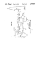
- FIG. 2 is a schematic block diagram of an apparatus in accordance with the present invention for controlling emissions of a fossil fuel fired boiler.
- the invention embodied therein comprises an apparatus for controlling the emissions of a fossil fuel fired boiler 10, and in particular a coal-fired boiler.
- Boiler 10 includes an economizer 22 which receives combustion fuel gases from the boiler.
- the flue gases are provided on a flue gas stream in an exhaust duct 23 connected to a baghouse 24.
- Ammonia is injected into the gas stream at 25 and alkali is injected into the gas stream at 26. Both alkali and ammonia are injected upstream of the baghouse 24.
- the baghouse contains, for example, ceramic fabric bags appropriate for high temperature baghouse operation.
- the SO x chemically reacts with the alkali to form a solid sulfated material.
- NO x chemically reacts with some of the alkali material and also with the ammonia.
- the NO x and ammonia reaction is enhanced when the gases pass through the catalyst that is contained in the baghouse and NO x is converted to harmless nitrogen and water.
- the particulate formed during the combustion process and by the chemical reaction between the SO x , NO x , alkali and ammonia, is collected at the surface of the bag filter. After a selected period of time the accumulation is removed in a conventional manner.
- heat pipe air heater 28 is the horizontal gas flow heat pipe unit available from Hudson Products Corporation of Houston, Texas.
- the heat pipe air heater 28 is modified with tightly spaced fins to the heat pipe tubes to increase the available surface area.
- the air heater contains a finned tube heat exchanger that, according to the invention, is advantageously coated with a catalyst for providing a final stage of NO x reduction. This results in two positive benefits. Because of the area of tight surface spacing due to the tightly spaced fins, the first positive benefit is a smaller, more compact heat exchanger, and the second benefit is more surface to apply the catalyst to. The total effectiveness of the catalyst is directly dependent upon the total surface area available.
- the clean flue gas exits along duct 29 and an induction draft fan 30 to stack 32.
- Fresh combustion air is supplied by fan 34 along a combustion air duct 35 through the air heater 28. Boiler 10 is thus supplied with heated combustion air.
- Ash from baghouse 24 can be discharged at 40 or supplied to a regenerator 42 for regenerating the alkali or regent/catalyst at 44.
- the regenerated reagent/catalyst can be mixed with fresh alkali at 45 for supply along line 26 to the flue gas stream.
- the system By combining the baghouse and heat pipe air heater technologies in the manner shown, the system enchances the operation of both and results in a superior overall system.
- a major advantage of the system is in its simplicity when compared to currently available options. The simplicity of the system results in low capital costs for initial installation and low operating cost thereafter.
- reagents/catalyst compounds are NaHCO 3 , nahcolite (which contains 10% "natural” Na 2 CO 3 , which was not as reactive Na 2 CO 3 formed from NaHCO 3 decomposing), Ca(OH) 2 , CaO, Cu 2 O, CuO, NaA10 2 , and ZnO.
Abstract
Description
Claims (3)
Priority Applications (1)
| Application Number | Priority Date | Filing Date | Title |
|---|---|---|---|
| US07/322,312 US4925633A (en) | 1988-07-25 | 1989-03-10 | Combined catalytic baghouse and heat pipe air heater |
Applications Claiming Priority (2)
| Application Number | Priority Date | Filing Date | Title |
|---|---|---|---|
| US07/224,419 US4871522A (en) | 1988-07-25 | 1988-07-25 | Combined catalytic baghouse and heat pipe air heater |
| US07/322,312 US4925633A (en) | 1988-07-25 | 1989-03-10 | Combined catalytic baghouse and heat pipe air heater |
Related Parent Applications (1)
| Application Number | Title | Priority Date | Filing Date |
|---|---|---|---|
| US07/224,419 Division US4871522A (en) | 1988-07-25 | 1988-07-25 | Combined catalytic baghouse and heat pipe air heater |
Publications (1)
| Publication Number | Publication Date |
|---|---|
| US4925633A true US4925633A (en) | 1990-05-15 |
Family
ID=26918690
Family Applications (1)
| Application Number | Title | Priority Date | Filing Date |
|---|---|---|---|
| US07/322,312 Expired - Lifetime US4925633A (en) | 1988-07-25 | 1989-03-10 | Combined catalytic baghouse and heat pipe air heater |
Country Status (1)
| Country | Link |
|---|---|
| US (1) | US4925633A (en) |
Cited By (21)
| Publication number | Priority date | Publication date | Assignee | Title |
|---|---|---|---|---|
| US5318755A (en) * | 1992-11-30 | 1994-06-07 | A. Ahlstrom Corporation | Method and apparatus for cleaning flue gases |
| US5424044A (en) * | 1994-03-23 | 1995-06-13 | The Babcock & Wilcox Company | Integrated SCR electrostatic precipitator |
| US5462718A (en) * | 1994-06-13 | 1995-10-31 | Foster Wheeler Energy Corporation | System for decreasing NOx emissions from a fluidized bed reactor |
| EP0885649A1 (en) * | 1997-06-20 | 1998-12-23 | Von Roll Umwelttechnik AG | Process for the denitration of combustion exhaust gases |
| US20030059460A1 (en) * | 2001-09-27 | 2003-03-27 | Yasuhiko Tabata | Hybrid material for regeneration of living body tissue |
| US6579507B2 (en) | 2000-08-01 | 2003-06-17 | Enviroscrub Technologies Corporation | System and process for removal of pollutants from a gas stream |
| US20030219368A1 (en) * | 2001-12-21 | 2003-11-27 | Hammel Charles F. | Pretreatment and regeneration of oxides of manganese |
| US20040018936A1 (en) * | 2002-03-06 | 2004-01-29 | Hammel Charles F. | Regeneration, pretreatment and precipitation of oxides of manganese |
| US20040258609A1 (en) * | 2003-01-28 | 2004-12-23 | Boren Richard M. | Oxides of manganese processed in continuous flow reactors |
| US20050074380A1 (en) * | 2003-07-31 | 2005-04-07 | Boren Richard M. | Metal oxide processing methods and systems |
| US20050084437A1 (en) * | 2003-10-20 | 2005-04-21 | Enviroserve Associates, L.L.C. | Scrubbing systems and methods for coal fired combustion units |
| EP1820560A1 (en) * | 2006-02-16 | 2007-08-22 | Siemens Aktiengesellschaft | Steam Generator with catalytic coating of heat exchanger surfaces for exhaust gas purification |
| US20090191114A1 (en) * | 2008-01-28 | 2009-07-30 | Jian Liu | Method for preparing ammonium bicarbonate with flue gas and devices thereof |
| US20100273643A1 (en) * | 2009-04-22 | 2010-10-28 | Gadgil Mandar R | System and method for protection of scr catalyst and control of multiple emissions |
| US20110076215A1 (en) * | 2009-09-25 | 2011-03-31 | Babcock Power Environmental Inc. | Integrated boiler and air pollution control systems |
| US20110229388A1 (en) * | 2009-04-22 | 2011-09-22 | Gadgil Mandar R | System and method for increasing the service life and/or catalytic activity of an scr catalyst and control of multiple emissions |
| US8303919B2 (en) | 2010-10-21 | 2012-11-06 | Babcock & Wilcox Power Generation Group, Inc. | System and method for protection of SCR catalyst and control of multiple emissions |
| US20180119544A1 (en) * | 2016-10-27 | 2018-05-03 | Steve Smith | Systems and methods for monitoring and managing wellhead emissions |
| US10213738B2 (en) | 2009-04-22 | 2019-02-26 | The Babcock & Wilcox Company | System and method for increasing the service life and/or catalytic activity of an SCR catalyst and control of multiple emissions |
| US10471384B2 (en) | 2009-04-22 | 2019-11-12 | The Babcock & Wilcox Company | System and method for reducing halogen levels necessary for mercury control, increasing the service life and/or catalytic activity of an SCR catalyst and/or control of multiple emissions |
| RU2759275C2 (en) * | 2017-04-26 | 2021-11-11 | Хальдор Топсёэ А/С | Method and system for removing nitrogenous compounds from flue gas using cloth filter bags and scr catalyst |
Citations (6)
| Publication number | Priority date | Publication date | Assignee | Title |
|---|---|---|---|---|
| US4309386A (en) * | 1979-04-30 | 1982-01-05 | The Babcock & Wilcox Company | Filter house having catalytic filter bags for simultaneously removing NOx and particulate matter from a gas stream |
| US4324570A (en) * | 1979-05-10 | 1982-04-13 | Basf Aktiengesellschaft | Apparatus for de-dusting gases |
| US4434147A (en) * | 1981-10-05 | 1984-02-28 | Chevron Research Company | Simultaneous sulfur oxide and nitrogen oxide control in FCC units using cracking catalyst fines with ammonia injection |
| US4602673A (en) * | 1983-10-03 | 1986-07-29 | L. & C. Steinmuller Gmbh | Apparatus for preheating combustion air, accompanied by simultaneous reduction of NOx contained in the flue gases |
| WO1986006711A1 (en) * | 1985-05-14 | 1986-11-20 | Gordon Dale Jones | Process and apparatus for removing oxides of nitrogen and sulfur from combustion gases |
| US4793981A (en) * | 1986-11-19 | 1988-12-27 | The Babcock & Wilcox Company | Integrated injection and bag filter house system for SOx -NOx -particulate control with reagent/catalyst regeneration |
-
1989
- 1989-03-10 US US07/322,312 patent/US4925633A/en not_active Expired - Lifetime
Patent Citations (7)
| Publication number | Priority date | Publication date | Assignee | Title |
|---|---|---|---|---|
| US4309386A (en) * | 1979-04-30 | 1982-01-05 | The Babcock & Wilcox Company | Filter house having catalytic filter bags for simultaneously removing NOx and particulate matter from a gas stream |
| US4324570A (en) * | 1979-05-10 | 1982-04-13 | Basf Aktiengesellschaft | Apparatus for de-dusting gases |
| US4434147A (en) * | 1981-10-05 | 1984-02-28 | Chevron Research Company | Simultaneous sulfur oxide and nitrogen oxide control in FCC units using cracking catalyst fines with ammonia injection |
| US4602673A (en) * | 1983-10-03 | 1986-07-29 | L. & C. Steinmuller Gmbh | Apparatus for preheating combustion air, accompanied by simultaneous reduction of NOx contained in the flue gases |
| WO1986006711A1 (en) * | 1985-05-14 | 1986-11-20 | Gordon Dale Jones | Process and apparatus for removing oxides of nitrogen and sulfur from combustion gases |
| US4783325A (en) * | 1985-05-14 | 1988-11-08 | Jones Dale G | Process and apparatus for removing oxides of nitrogen and sulfur from combustion gases |
| US4793981A (en) * | 1986-11-19 | 1988-12-27 | The Babcock & Wilcox Company | Integrated injection and bag filter house system for SOx -NOx -particulate control with reagent/catalyst regeneration |
Cited By (42)
| Publication number | Priority date | Publication date | Assignee | Title |
|---|---|---|---|---|
| US5318755A (en) * | 1992-11-30 | 1994-06-07 | A. Ahlstrom Corporation | Method and apparatus for cleaning flue gases |
| US5424044A (en) * | 1994-03-23 | 1995-06-13 | The Babcock & Wilcox Company | Integrated SCR electrostatic precipitator |
| US5462718A (en) * | 1994-06-13 | 1995-10-31 | Foster Wheeler Energy Corporation | System for decreasing NOx emissions from a fluidized bed reactor |
| EP0885649A1 (en) * | 1997-06-20 | 1998-12-23 | Von Roll Umwelttechnik AG | Process for the denitration of combustion exhaust gases |
| US20030157008A1 (en) * | 2000-08-01 | 2003-08-21 | Enviroscrub Technologies Corporation | System and process for removal of pollutants from a gas stream |
| US6579507B2 (en) | 2000-08-01 | 2003-06-17 | Enviroscrub Technologies Corporation | System and process for removal of pollutants from a gas stream |
| US6610263B2 (en) | 2000-08-01 | 2003-08-26 | Enviroscrub Technologies Corporation | System and process for removal of pollutants from a gas stream |
| US7396514B2 (en) | 2000-08-01 | 2008-07-08 | Enviroscrub Technologies Corporation | Electronic controls for pollutant removal |
| US20050238549A1 (en) * | 2000-08-01 | 2005-10-27 | Enviroscrub Technologies Corporation | Electronic controls for pollutant removal |
| US7033548B2 (en) | 2000-08-01 | 2006-04-25 | Enviroscrub Technologies Corporation | System and process for removal of pollutants from a gas stream |
| US20030059460A1 (en) * | 2001-09-27 | 2003-03-27 | Yasuhiko Tabata | Hybrid material for regeneration of living body tissue |
| US7041270B2 (en) | 2001-12-21 | 2006-05-09 | Enviroscrub Technologies Corporation | Pretreatment and regeneration of oxides of manganese |
| US20030219368A1 (en) * | 2001-12-21 | 2003-11-27 | Hammel Charles F. | Pretreatment and regeneration of oxides of manganese |
| US20040018936A1 (en) * | 2002-03-06 | 2004-01-29 | Hammel Charles F. | Regeneration, pretreatment and precipitation of oxides of manganese |
| US7232782B2 (en) | 2002-03-06 | 2007-06-19 | Enviroscrub Technologies Corp. | Regeneration, pretreatment and precipitation of oxides of manganese |
| US20040258609A1 (en) * | 2003-01-28 | 2004-12-23 | Boren Richard M. | Oxides of manganese processed in continuous flow reactors |
| US7419637B2 (en) | 2003-01-28 | 2008-09-02 | Enviroscrub Technologies Corporation | Oxides of manganese processed in continuous flow reactors |
| US20080317650A1 (en) * | 2003-01-28 | 2008-12-25 | Boren Richard M | Oxides of Manganese Processed in Continuous Flow Reactors |
| US20100059428A1 (en) * | 2003-07-31 | 2010-03-11 | Boren Richard M | System for Removal of Metals from Aqueous Solutions |
| US7488464B2 (en) | 2003-07-31 | 2009-02-10 | Enviroscrub Technologies Corporation | Metal oxide processing methods and systems |
| US20050074380A1 (en) * | 2003-07-31 | 2005-04-07 | Boren Richard M. | Metal oxide processing methods and systems |
| US20050084437A1 (en) * | 2003-10-20 | 2005-04-21 | Enviroserve Associates, L.L.C. | Scrubbing systems and methods for coal fired combustion units |
| WO2007093453A3 (en) * | 2006-02-16 | 2007-10-25 | Siemens Ag | Steam generator with heat exchanger surfaces that are provided with a catalytic coating for cleaning waste gas |
| WO2007093453A2 (en) * | 2006-02-16 | 2007-08-23 | Siemens Aktiengesellschaft | Steam generator with heat exchanger surfaces that are provided with a catalytic coating for cleaning waste gas |
| EP1820560A1 (en) * | 2006-02-16 | 2007-08-22 | Siemens Aktiengesellschaft | Steam Generator with catalytic coating of heat exchanger surfaces for exhaust gas purification |
| US20110041783A1 (en) * | 2006-02-16 | 2011-02-24 | Brueckner Jan | Steam Generator |
| US20090191114A1 (en) * | 2008-01-28 | 2009-07-30 | Jian Liu | Method for preparing ammonium bicarbonate with flue gas and devices thereof |
| US8287830B2 (en) * | 2008-01-28 | 2012-10-16 | Jain Liu | Devices for preparing ammonium bicarbonate with flue gas and method of using the devices |
| US20100273643A1 (en) * | 2009-04-22 | 2010-10-28 | Gadgil Mandar R | System and method for protection of scr catalyst and control of multiple emissions |
| US8691719B2 (en) | 2009-04-22 | 2014-04-08 | Babcock & Wilcox Power Generation Group, Inc. | System and method for increasing the service life and/or catalytic activity of an SCR catalyst and control of multiple emissions |
| US10471384B2 (en) | 2009-04-22 | 2019-11-12 | The Babcock & Wilcox Company | System and method for reducing halogen levels necessary for mercury control, increasing the service life and/or catalytic activity of an SCR catalyst and/or control of multiple emissions |
| US10213738B2 (en) | 2009-04-22 | 2019-02-26 | The Babcock & Wilcox Company | System and method for increasing the service life and/or catalytic activity of an SCR catalyst and control of multiple emissions |
| US20110229388A1 (en) * | 2009-04-22 | 2011-09-22 | Gadgil Mandar R | System and method for increasing the service life and/or catalytic activity of an scr catalyst and control of multiple emissions |
| US8716169B2 (en) | 2009-04-22 | 2014-05-06 | Babcock & Wilcox Power Generation Group, Inc. | System and method for protection of SCR catalyst and control of multiple emissions |
| US20110076215A1 (en) * | 2009-09-25 | 2011-03-31 | Babcock Power Environmental Inc. | Integrated boiler and air pollution control systems |
| US8142744B2 (en) | 2009-09-25 | 2012-03-27 | Babcock Power Environmental Inc. | Integrated boiler and air pollution control systems |
| US20110165042A1 (en) * | 2009-09-25 | 2011-07-07 | Babcock Power Environmental Inc. | Integrated boiler and air pollution control systems |
| US7931881B2 (en) | 2009-09-25 | 2011-04-26 | Babcock Power Environmental Inc. | Integrated boiler and air pollution control systems |
| US8303919B2 (en) | 2010-10-21 | 2012-11-06 | Babcock & Wilcox Power Generation Group, Inc. | System and method for protection of SCR catalyst and control of multiple emissions |
| US20180119544A1 (en) * | 2016-10-27 | 2018-05-03 | Steve Smith | Systems and methods for monitoring and managing wellhead emissions |
| US10753204B2 (en) * | 2016-10-27 | 2020-08-25 | Steve Smith | Systems and methods for monitoring and managing wellhead emissions |
| RU2759275C2 (en) * | 2017-04-26 | 2021-11-11 | Хальдор Топсёэ А/С | Method and system for removing nitrogenous compounds from flue gas using cloth filter bags and scr catalyst |
Similar Documents
| Publication | Publication Date | Title |
|---|---|---|
| US4871522A (en) | Combined catalytic baghouse and heat pipe air heater | |
| US4925633A (en) | Combined catalytic baghouse and heat pipe air heater | |
| US5567394A (en) | SOx , NOx , and particulate removal system | |
| US8808652B2 (en) | Biomass boiler SCR NOx and CO reduction system | |
| US5814288A (en) | Flue gas desulfurization method and apparatus | |
| US4956162A (en) | Process for removal of particulates and SO2 from combustion gases | |
| EP2760564B1 (en) | Dry sorbent injection during steady-state conditions in dry scrubber | |
| EP2760565B1 (en) | Dry sorbent injection during non-steady state conditons in dry scrubber | |
| CN201643982U (en) | FCC flue gas denitration catalytic reactor | |
| JPS5824174B2 (en) | Exhaust gas treatment method | |
| CN100589866C (en) | Emission control systems and methods thereof | |
| WO1998003249A1 (en) | Flue gas cleaning device with catalytic ceramic filter | |
| CN111282419A (en) | Dry type purification process and device for multiple pollutants in flue gas of incinerator | |
| CN110252051B (en) | Method for dedusting, desulfurizing and denitrating boiler flue gas and removing dioxin | |
| CN215388629U (en) | Pollutant collaborative purification system for waste incineration flue gas | |
| CN211925773U (en) | Flue gas deacidification dust, nitre and oxazole integrated treatment system for garbage incinerator | |
| CN212091626U (en) | Dry type purification device for multiple pollutants in flue gas of incinerator | |
| JPH09243050A (en) | Exhaust gas treatment method and apparatus | |
| CN211435702U (en) | Multi-pollutant integrated removing system of circulating fluidized bed boiler | |
| CN115634557A (en) | Pollutant collaborative purification system for waste incineration flue gas | |
| Zagala et al. | Flue gas cleaning systems-A review paper | |
| CN207137657U (en) | A kind of coal-fired flue-gas dust-removing denitrification integrated device | |
| JP3489938B2 (en) | Flue gas treatment equipment | |
| Chu et al. | Improved SOx, NOx, and particulate removal system | |
| CN210241609U (en) | Boiler flue gas desulfurization denitration dust pelletizing system |
Legal Events
| Date | Code | Title | Description |
|---|---|---|---|
| STCF | Information on status: patent grant |
Free format text: PATENTED CASE |
|
| FEPP | Fee payment procedure |
Free format text: PAYOR NUMBER ASSIGNED (ORIGINAL EVENT CODE: ASPN); ENTITY STATUS OF PATENT OWNER: LARGE ENTITY |
|
| FPAY | Fee payment |
Year of fee payment: 4 |
|
| FPAY | Fee payment |
Year of fee payment: 8 |
|
| AS | Assignment |
Owner name: MCDERMOTT TECHNOLOGY, INC., LOUISIANA Free format text: ASSIGNMENT OF ASSIGNORS INTEREST;ASSIGNOR:BABCOCK & WILCOX COMPANY, THE;REEL/FRAME:009396/0001 Effective date: 19980618 |
|
| FPAY | Fee payment |
Year of fee payment: 12 |
|
| REMI | Maintenance fee reminder mailed | ||
| AS | Assignment |
Owner name: THE BABCOCK & WILCOX COMPANY, OHIO Free format text: ASSIGNMENT OF ASSIGNORS INTEREST;ASSIGNOR:MCDERMOTT TECHNOLOGY, INC.;REEL/FRAME:017186/0749 Effective date: 20060221 |
|
| AS | Assignment |
Owner name: CREDIT SUISSE, CAYMAN ISLANDS BRANCH, AS COLLATERA Free format text: SECURITY AGREEMENT;ASSIGNOR:THE BABCOCK & WILCOX COMPANY;REEL/FRAME:017344/0565 Effective date: 20060222 |
|
| AS | Assignment |
Owner name: THE BABCOCK & WILCOX POWER GENERATION GROUP, INC., Free format text: CHANGE OF NAME;ASSIGNOR:THE BABCOCK & WILCOX COMPANY;REEL/FRAME:021998/0870 Effective date: 20071120 |
|
| AS | Assignment |
Owner name: POWER SYSTEMS OPERATIONS, INC., OHIO Free format text: RELEASE BY SECURED PARTY;ASSIGNOR:CREDIT SUISSE AG, CAYMAN ISLANDS BRANCH;REEL/FRAME:024776/0693 Effective date: 20100503 Owner name: BABCOCK & WILCOX INTERNATIONAL, INC., OHIO Free format text: RELEASE BY SECURED PARTY;ASSIGNOR:CREDIT SUISSE AG, CAYMAN ISLANDS BRANCH;REEL/FRAME:024776/0693 Effective date: 20100503 Owner name: DIAMOND POWER CHINA HOLDINGS, INC., OHIO Free format text: RELEASE BY SECURED PARTY;ASSIGNOR:CREDIT SUISSE AG, CAYMAN ISLANDS BRANCH;REEL/FRAME:024776/0693 Effective date: 20100503 Owner name: NATIONAL ECOLOGY COMPANY, OHIO Free format text: RELEASE BY SECURED PARTY;ASSIGNOR:CREDIT SUISSE AG, CAYMAN ISLANDS BRANCH;REEL/FRAME:024776/0693 Effective date: 20100503 Owner name: B & W SERVICE COMPANY, NORTH CAROLINA Free format text: RELEASE BY SECURED PARTY;ASSIGNOR:CREDIT SUISSE AG, CAYMAN ISLANDS BRANCH;REEL/FRAME:024776/0693 Effective date: 20100503 Owner name: BABCOCK & WILCOX EQUITY INVESTMENTS, INC., OHIO Free format text: RELEASE BY SECURED PARTY;ASSIGNOR:CREDIT SUISSE AG, CAYMAN ISLANDS BRANCH;REEL/FRAME:024776/0693 Effective date: 20100503 Owner name: APPLIED SYNERGISTICS, INC., VIRGINIA Free format text: RELEASE BY SECURED PARTY;ASSIGNOR:CREDIT SUISSE AG, CAYMAN ISLANDS BRANCH;REEL/FRAME:024776/0693 Effective date: 20100503 Owner name: REVLOC RECLAMATION SERVICE, INC., OHIO Free format text: RELEASE BY SECURED PARTY;ASSIGNOR:CREDIT SUISSE AG, CAYMAN ISLANDS BRANCH;REEL/FRAME:024776/0693 Effective date: 20100503 Owner name: DIAMOND POWER AUSTRALIA HOLDINGS, INC., OHIO Free format text: RELEASE BY SECURED PARTY;ASSIGNOR:CREDIT SUISSE AG, CAYMAN ISLANDS BRANCH;REEL/FRAME:024776/0693 Effective date: 20100503 Owner name: THE BABCOCK & WILCOX COMPANY, NORTH CAROLINA Free format text: RELEASE BY SECURED PARTY;ASSIGNOR:CREDIT SUISSE AG, CAYMAN ISLANDS BRANCH;REEL/FRAME:024776/0693 Effective date: 20100503 Owner name: NORTH COUNTY RECYCLING, INC., NORTH CAROLINA Free format text: RELEASE BY SECURED PARTY;ASSIGNOR:CREDIT SUISSE AG, CAYMAN ISLANDS BRANCH;REEL/FRAME:024776/0693 Effective date: 20100503 Owner name: BABCOCK & WILCOX EBENSBURG POWER, INC., OHIO Free format text: RELEASE BY SECURED PARTY;ASSIGNOR:CREDIT SUISSE AG, CAYMAN ISLANDS BRANCH;REEL/FRAME:024776/0693 Effective date: 20100503 Owner name: BABCOCK & WILCOX INTERNATIONAL SALES AND SERVICE C Free format text: RELEASE BY SECURED PARTY;ASSIGNOR:CREDIT SUISSE AG, CAYMAN ISLANDS BRANCH;REEL/FRAME:024776/0693 Effective date: 20100503 Owner name: DIAMOND POWER INTERNATIONAL, INC., OHIO Free format text: RELEASE BY SECURED PARTY;ASSIGNOR:CREDIT SUISSE AG, CAYMAN ISLANDS BRANCH;REEL/FRAME:024776/0693 Effective date: 20100503 Owner name: DIAMOND POWER EQUITY INVESTMENTS, INC., OHIO Free format text: RELEASE BY SECURED PARTY;ASSIGNOR:CREDIT SUISSE AG, CAYMAN ISLANDS BRANCH;REEL/FRAME:024776/0693 Effective date: 20100503 Owner name: BABCOCK & WILCOX DENMARK HOLDINGS, INC., OHIO Free format text: RELEASE BY SECURED PARTY;ASSIGNOR:CREDIT SUISSE AG, CAYMAN ISLANDS BRANCH;REEL/FRAME:024776/0693 Effective date: 20100503 Owner name: AMERICON EQUIPMENT SERVICES, INC., OHIO Free format text: RELEASE BY SECURED PARTY;ASSIGNOR:CREDIT SUISSE AG, CAYMAN ISLANDS BRANCH;REEL/FRAME:024776/0693 Effective date: 20100503 Owner name: DIAMOND OPERATING CO., INC., PENNSYLVANIA Free format text: RELEASE BY SECURED PARTY;ASSIGNOR:CREDIT SUISSE AG, CAYMAN ISLANDS BRANCH;REEL/FRAME:024776/0693 Effective date: 20100503 Owner name: AMERICON, INC., OHIO Free format text: RELEASE BY SECURED PARTY;ASSIGNOR:CREDIT SUISSE AG, CAYMAN ISLANDS BRANCH;REEL/FRAME:024776/0693 Effective date: 20100503 Owner name: BABCOCK & WILCOX CHINA HOLDINGS, INC., OHIO Free format text: RELEASE BY SECURED PARTY;ASSIGNOR:CREDIT SUISSE AG, CAYMAN ISLANDS BRANCH;REEL/FRAME:024776/0693 Effective date: 20100503 Owner name: BABCOCK & WILCOX CONSTRUCTION CO., INC., OHIO Free format text: RELEASE BY SECURED PARTY;ASSIGNOR:CREDIT SUISSE AG, CAYMAN ISLANDS BRANCH;REEL/FRAME:024776/0693 Effective date: 20100503 Owner name: PALM BEACH RESOURCE RECOVERY CORPORATION, FLORIDA Free format text: RELEASE BY SECURED PARTY;ASSIGNOR:CREDIT SUISSE AG, CAYMAN ISLANDS BRANCH;REEL/FRAME:024776/0693 Effective date: 20100503 |