EP0219887A2 - Strahlungs- und Konvektionsapparat - Google Patents
Strahlungs- und Konvektionsapparat Download PDFInfo
- Publication number
- EP0219887A2 EP0219887A2 EP86115188A EP86115188A EP0219887A2 EP 0219887 A2 EP0219887 A2 EP 0219887A2 EP 86115188 A EP86115188 A EP 86115188A EP 86115188 A EP86115188 A EP 86115188A EP 0219887 A2 EP0219887 A2 EP 0219887A2
- Authority
- EP
- European Patent Office
- Prior art keywords
- heat
- convection
- slots
- open
- compartments
- Prior art date
- Legal status (The legal status is an assumption and is not a legal conclusion. Google has not performed a legal analysis and makes no representation as to the accuracy of the status listed.)
- Granted
Links
Images
Classifications
-
- F—MECHANICAL ENGINEERING; LIGHTING; HEATING; WEAPONS; BLASTING
- F28—HEAT EXCHANGE IN GENERAL
- F28D—HEAT-EXCHANGE APPARATUS, NOT PROVIDED FOR IN ANOTHER SUBCLASS, IN WHICH THE HEAT-EXCHANGE MEDIA DO NOT COME INTO DIRECT CONTACT
- F28D1/00—Heat-exchange apparatus having stationary conduit assemblies for one heat-exchange medium only, the media being in contact with different sides of the conduit wall, in which the other heat-exchange medium is a large body of fluid, e.g. domestic or motor car radiators
- F28D1/02—Heat-exchange apparatus having stationary conduit assemblies for one heat-exchange medium only, the media being in contact with different sides of the conduit wall, in which the other heat-exchange medium is a large body of fluid, e.g. domestic or motor car radiators with heat-exchange conduits immersed in the body of fluid
- F28D1/0233—Heat-exchange apparatus having stationary conduit assemblies for one heat-exchange medium only, the media being in contact with different sides of the conduit wall, in which the other heat-exchange medium is a large body of fluid, e.g. domestic or motor car radiators with heat-exchange conduits immersed in the body of fluid with air flow channels
-
- F—MECHANICAL ENGINEERING; LIGHTING; HEATING; WEAPONS; BLASTING
- F24—HEATING; RANGES; VENTILATING
- F24D—DOMESTIC- OR SPACE-HEATING SYSTEMS, e.g. CENTRAL HEATING SYSTEMS; DOMESTIC HOT-WATER SUPPLY SYSTEMS; ELEMENTS OR COMPONENTS THEREFOR
- F24D3/00—Hot-water central heating systems
- F24D3/12—Tube and panel arrangements for ceiling, wall, or underfloor heating
- F24D3/14—Tube and panel arrangements for ceiling, wall, or underfloor heating incorporated in a ceiling, wall or floor
- F24D3/147—Tube and panel arrangements for ceiling, wall, or underfloor heating incorporated in a ceiling, wall or floor arranged in facades
-
- F—MECHANICAL ENGINEERING; LIGHTING; HEATING; WEAPONS; BLASTING
- F28—HEAT EXCHANGE IN GENERAL
- F28D—HEAT-EXCHANGE APPARATUS, NOT PROVIDED FOR IN ANOTHER SUBCLASS, IN WHICH THE HEAT-EXCHANGE MEDIA DO NOT COME INTO DIRECT CONTACT
- F28D1/00—Heat-exchange apparatus having stationary conduit assemblies for one heat-exchange medium only, the media being in contact with different sides of the conduit wall, in which the other heat-exchange medium is a large body of fluid, e.g. domestic or motor car radiators
- F28D1/02—Heat-exchange apparatus having stationary conduit assemblies for one heat-exchange medium only, the media being in contact with different sides of the conduit wall, in which the other heat-exchange medium is a large body of fluid, e.g. domestic or motor car radiators with heat-exchange conduits immersed in the body of fluid
- F28D1/04—Heat-exchange apparatus having stationary conduit assemblies for one heat-exchange medium only, the media being in contact with different sides of the conduit wall, in which the other heat-exchange medium is a large body of fluid, e.g. domestic or motor car radiators with heat-exchange conduits immersed in the body of fluid with tubular conduits
- F28D1/053—Heat-exchange apparatus having stationary conduit assemblies for one heat-exchange medium only, the media being in contact with different sides of the conduit wall, in which the other heat-exchange medium is a large body of fluid, e.g. domestic or motor car radiators with heat-exchange conduits immersed in the body of fluid with tubular conduits the conduits being straight
-
- F—MECHANICAL ENGINEERING; LIGHTING; HEATING; WEAPONS; BLASTING
- F28—HEAT EXCHANGE IN GENERAL
- F28F—DETAILS OF HEAT-EXCHANGE AND HEAT-TRANSFER APPARATUS, OF GENERAL APPLICATION
- F28F1/00—Tubular elements; Assemblies of tubular elements
- F28F1/10—Tubular elements and assemblies thereof with means for increasing heat-transfer area, e.g. with fins, with projections, with recesses
- F28F1/12—Tubular elements and assemblies thereof with means for increasing heat-transfer area, e.g. with fins, with projections, with recesses the means being only outside the tubular element
- F28F1/24—Tubular elements and assemblies thereof with means for increasing heat-transfer area, e.g. with fins, with projections, with recesses the means being only outside the tubular element and extending transversely
-
- Y—GENERAL TAGGING OF NEW TECHNOLOGICAL DEVELOPMENTS; GENERAL TAGGING OF CROSS-SECTIONAL TECHNOLOGIES SPANNING OVER SEVERAL SECTIONS OF THE IPC; TECHNICAL SUBJECTS COVERED BY FORMER USPC CROSS-REFERENCE ART COLLECTIONS [XRACs] AND DIGESTS
- Y02—TECHNOLOGIES OR APPLICATIONS FOR MITIGATION OR ADAPTATION AGAINST CLIMATE CHANGE
- Y02B—CLIMATE CHANGE MITIGATION TECHNOLOGIES RELATED TO BUILDINGS, e.g. HOUSING, HOUSE APPLIANCES OR RELATED END-USER APPLICATIONS
- Y02B30/00—Energy efficient heating, ventilation or air conditioning [HVAC]
Definitions
- the present invention relates to a radiation and convection apparatus for ceiling installation consisting of elongated heat exchangers which is arranged in heat-conducting contact with the vertical, side walls of an apparatus housing which is open at the top and bottom and through which an air stream can flow.
- the purpose of the invention is to provide an apparatus of the type mentioned at the outset with which it is possible to combine the absorption or dissipation of heat by radiation with direct cooling or heating by convection and ventilation in one and the same apparatus.
- the device should be space-saving, simple and cheap to manufacture.
- the Appliance housing is divided into three compartments, two lateral compartments in each of which a heat exchanger in the form of a finned tube battery is arranged and which are open at the top and sides at the bottom by means of slots, and a central compartment which forms a ventilation duct that extends through openings that face the slots are arranged to support the convection air flow through the side compartments by induction.
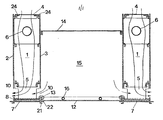
- the radiation and convection apparatus is composed of light metal profiles which form an apparatus housing 1 open at the top and bottom, the side walls 2 and 3 of which are held together by means of upper and lower clamps 4 and 5.
- a heat exchanger in the form of a finned tube battery 6 for a cooling medium is arranged in heat-conducting contact with the side walls 2 and 3, which are held by the clamping brackets 4 and 5 against the finned tube battery 6.
- the apparatus housing 1 also has a lower end wall 7, which is connected by means of snap closures 8 to flanges 9 projecting from the lower clamping brackets 5 at a distance from the lower end edges of the side walls 2 and 3. Air from the room can thus pass through the apparatus housing 1 along its entire length and be cooled by the finned tube battery 6, after which the cooled air exits through the slots 10 which are provided between the lower edges of the side walls 2 and 3 and the end wall 7 .
- the device thus functions as a radiation and convection device.
- the end wall 7 is trough-shaped and in this one can water-absorbing mat 11 may be arranged to accommodate any condensed water.
- Hanging devices in the form of pendulums for the apparatus housing 1 can be connected to the connecting flanges 24 and clamping brackets 4 on the upper end edges of the side walls 2 and 3.
- Two apparatus housings 1 are provided at the above-mentioned distance from one another and connected via a suspended ceiling panels 12 by means of tensioning brackets 13, and are provided with an upper cover plate 14.
- the space between two such apparatus housings 1, the suspended ceiling panels 12 and the cover plate 14 forms a ventilation duct 15, through which the room can be supplied with supply air via a blower (not shown). This flows into the room through the slots 10 in the apparatus housing, whereby air is drawn through the apparatus housing 1 by induction.
- a pipe loop 16 for a heating medium is arranged in heat-conducting contact with the suspended ceiling panels 12, so that the device 3 e can be used either for heating or cooling the room as required.
- the pipe loops 6 and 16 can preferably be components of a heat exchange system, so that excess heat absorbed during the day can be used at night to warm the rooms.
Landscapes
- Engineering & Computer Science (AREA)
- Physics & Mathematics (AREA)
- Thermal Sciences (AREA)
- Mechanical Engineering (AREA)
- General Engineering & Computer Science (AREA)
- Chemical & Material Sciences (AREA)
- Geometry (AREA)
- Combustion & Propulsion (AREA)
- Devices For Blowing Cold Air, Devices For Blowing Warm Air, And Means For Preventing Water Condensation In Air Conditioning Units (AREA)
- Analysing Materials By The Use Of Radiation (AREA)
- Electrochromic Elements, Electrophoresis, Or Variable Reflection Or Absorption Elements (AREA)
- Conversion Of X-Rays Into Visible Images (AREA)
- Cooling Or The Like Of Semiconductors Or Solid State Devices (AREA)
- Air-Conditioning Room Units, And Self-Contained Units In General (AREA)
- Buildings Adapted To Withstand Abnormal External Influences (AREA)
Abstract
Description
- Die vorliegende Erfindung betrifft einen Strahlungs- und Konvektionsapparat für Unterdeckenmontage bestehend aus länglichen Wärmeaustauschern die in wärmeleitender Berührung mit den vertikalen, Seitenwänden eines oben und unten offenen von einem Luftstrom durchströmbaren Apparatengehäuse angeordnet ist.
- Es ist bekannt Räume mit in Unterdeckenpaneele verlegte Rohrleitungen mit Warmwasser zu. erwärmen. Ebenso ist es bekannt Räume mit derartigen Paneelen zu kühlen, die Wärme von der Umgebung aufnehmen. Gewöhnlich ist das Kältemedium kaltes Wasser, mit einer Temperatur von etwa 12-16 C. Auf Grund der Kondensierungsgefahr der Feuchtigkeit in der Zimmerluft ist die Oberflächentemperatur der Rohrleitungen und der Paneele 0 auf Temperaturwerte von 12-16 C begrenzt. Auch wenn in dem Raum Temperaturen so hoch wie 26°C vorkommen können, wird der Temperaturunterschied zwischen Raum und Paneel nur 10-15 o betragen und die Wärmeaufnahme verhältnismässig gering sein. Die Wärmeaufnahme ist auf etwa 80 watt/m Paneelflache begrenzt. Auf Grund dieser verhältnismässig geringen Wärmeaufnahme ist der Preis für Unterdeckenpaneele pro Watt Kühleffekt relativ hoch. Meistens müssen die Paneele nach der maximalen Kühlbelastung berechnet werden.
- Zweck der Erfindung ist einen Apparat der eingangs erwähnten Art zu schaffen, mit welchem es möglich ist die Wärmeaufnahme bzw. -Abgabe durch Strahlung mit direkter Kühlung bzw. -Erwärmung durch Konvektion und Ventilation in ein und selben Apparat zu kombinieren. Der Apparat soll dabei platzsparend, einfach und billig in der Herstellung sein.
- Dies wurde erfindungsgemäss dadurch erreicht, dass das Apparatengehäuse in drei Abteilungen aufgeteilt ist, zwei seitliche Abteilungen in denen je ein Wärmeaustauscher in Form einer Rippenrohrbatterie angeordnet ist und die oben und seitlich unten mittels Schlitze offen sind, sowie einer mittleren Abteilung, welche einen Ventilationskanal bildet, der über Öffnungen, die gegenüber den Schlitzen angeordnet sind, den Konvektionsluftstrom durch die seitlichen Abteilungen durch Induktion unterstützen.
- Die Erfindung wird im folgenden mit Hinweis auf die beigefügte Zeichnung näher beschrieben, welche als Ausführungsbeispiel einen vertikalen Schnitt durch einen Strahlungs- und Konvektionsapparat gemäss der Erfindung zeigt.
- Der erfindungsgemässe Strahlungs- und Konvektionsapparat ist wird ein aus Leichtmetallprofilen zusammengestellt, die ein oben und unten offenes Apparatengehäuse 1 bilden, dessen Seitenwände 2 und 3 mittels oberen und unteren Spannbügel 4 und 5 zusammengehalten werden. Ein Wärmeaustauscher in Form einer Rippenrohrbatteri 6 für ein Kühlmedium ist in wärmeleitendem Kontakt mit den Seitenwänden 2 und 3 angeordnet, welche von den Spannbügeln 4 und 5 gegen die Rippenrohrbatterie 6 gehalten werden.
- Das Apparatengehäuse 1 weist weiter eine untere Endwand 7 auf, die mittels Schnappverschlüsse 8 mit von den unteren Spannbügeln 5 abstehenden Flanschen 9 auf Abstand von den unteren Endkanten der Seitenwände 2 und 3 verbunden ist. Luft aus dem Raum kann somit durch das Apparatengehäuse 1 längs dessen ganzer Länge hindurchpassieren und von der Rippenrohrbatterie 6 gekühlt werden, wonach die gekühlte Luft durch die Schlitze 10, die zwischen den unteren Kanten der Seitenwände 2 und 3 und der Endwand 7 vorgesehen sind, abgeht. Der Apparat fungiert somit als Strahlungs- und Konvektionsapparat. Die Endwand 7 ist trogförmig ausgebildet und in dieser kann eine wasserabsorbierende Matte 11 zur Aufnahme von eventuellem Kondenswasser angeordnet sein.
- Aufhängevorrichtungen in Form von Pendeln für das Apparatengehäuse 1 sind an Anschlussflansche 24 und Spannbügel 4 an den oberen Endkanten der Seitenwände 2 und 3 anschliessbar.
- Zwei Apparatengehäuse 1 auf der oben angegebenen Abstand voneinander vorgesehen und über eine Unterdeckenpaneele 12 mittels Spannbügel 13 verbunden, sowie mit einer oberen Abdeckplatte 14 versehen. Der Raum zwischen zwei solchen Apparatengehäuse 1, der Unterdeckenpaneele 12 und der Abdeckplatte 14 bildet einen Ventilationskanal 15, durch welchen das Zimmer über ein nicht näher dargestelltes Gebläse mit Zuluft gespeisst werden kann. Diese strömt in den Raum durch die Schlitze 10 im Apparatengehäuse, wobei sie durch Induktion Luft durch das Apparatengehäuse 1 mitsich zieht.
- Eine Rohrschlinge 16 für ein Wärmemedium ist in wärmeleitender Berührung mit der Unterdeckenpaneele 12 angeordnet, so dass die Vorrichtung 3e nach Bedarf entweder zum Erwärmen oder Kühlen des Raumes angewandt werden kann. Zur Tageszeit liegt normalerweise in z.B. Büro-, Geschäfts- und Industrieräumen, ausser während kalter Wintertage, ein Wärmeüberschuss bei Tag und Nachts ein Wärmebedarf vor. Die Rohrschlingen 6 und 16 können vorzugsweise Bestandteile eines Wärmeaustauschsystems sein, so dass während der Tageszeit aufgenommener WärmeOberschuss nachts zum Erwärmen der Räume angewandt werden kann.
Claims (5)
dadurch gekennzeichnet,
dass das Apparatengehäuse (1) in drei Abteilungen (1,15) aufgeteilt ist, zwei seitliche Abteilungen (1) in denen je ein Wärmeaustauscher in Form einer Rippenrphrbatterie angeordnet ist und die oben und seitlich unten mittels Schlitze (10) offen sind, sowie einer mittleren Abteilung (15), welche einen Ventilationskanal bildet, der uber Öffnungen, die gegenüber den Schlitzen (10) angeordnet sind, den Konvektionsluftstrom durch die seitlichen Abteilungen (1) durch Induktion unterstützen.
dadurch gekennzeichnet,
dass die Endwand (7) als Träger für mindestens eine an das Apparatengehäuse anschliessbare Unterdeckenpaneele (12) ausgebildet ist.
dadurch gekennzeichnet,
dass die Unterdeckenpaneele (12) zwischen zwei auf Abstand von einander liegende Apparatengehäuse (1) angeordnet und mit diesen verbunden ist.
dadurch gekennzeichnet,
dass die Unterdeckenpaneele (12) als Wärmeaustauscher ausgebildet ist.
dadurch gekennzeichnet.
dass zwischen zwei Apparatengehäusen (1) oberhalb der Unterdeckenpaneele (12) eine Abdeckplatte (14) vorgesehen ist, wodurch mindestens ein Luftkanal (15) gebildet wird.
Priority Applications (6)
| Application Number | Priority Date | Filing Date | Title |
|---|---|---|---|
| SE8402488A SE8402488D0 (sv) | 1984-05-09 | 1984-05-09 | Kyl- eller kyl- och ventilationsanordning |
| NO85851849A NO158697C (no) | 1984-05-09 | 1985-05-09 | Straalings- og konveksjonselement. |
| FI851846A FI77111C (fi) | 1984-05-09 | 1985-05-09 | Straolnings- och konvektionselement. |
| DK206285A DK206285A (da) | 1984-05-09 | 1985-05-09 | Straalings- og konvektionselement |
| AT86115188T ATE43007T1 (de) | 1985-05-09 | 1986-05-07 | Strahlungs- und konvektionsapparat. |
| EP86115188A EP0219887B1 (de) | 1985-05-09 | 1986-05-07 | Strahlungs- und Konvektionsapparat |
Applications Claiming Priority (3)
| Application Number | Priority Date | Filing Date | Title |
|---|---|---|---|
| NO85851849A NO158697C (no) | 1984-05-09 | 1985-05-09 | Straalings- og konveksjonselement. |
| NO851849 | 1985-05-09 | ||
| EP86115188A EP0219887B1 (de) | 1985-05-09 | 1986-05-07 | Strahlungs- und Konvektionsapparat |
Related Parent Applications (1)
| Application Number | Title | Priority Date | Filing Date |
|---|---|---|---|
| EP86850164.4 Division | 1986-05-07 |
Publications (3)
| Publication Number | Publication Date |
|---|---|
| EP0219887A2 true EP0219887A2 (de) | 1987-04-29 |
| EP0219887A3 EP0219887A3 (en) | 1987-06-03 |
| EP0219887B1 EP0219887B1 (de) | 1989-05-10 |
Family
ID=19888276
Family Applications (2)
| Application Number | Title | Priority Date | Filing Date |
|---|---|---|---|
| EP86850164A Expired EP0201473B1 (de) | 1985-05-09 | 1986-05-07 | Strahlungs- und Konvektionsapparat |
| EP86115188A Expired EP0219887B1 (de) | 1984-05-09 | 1986-05-07 | Strahlungs- und Konvektionsapparat |
Family Applications Before (1)
| Application Number | Title | Priority Date | Filing Date |
|---|---|---|---|
| EP86850164A Expired EP0201473B1 (de) | 1985-05-09 | 1986-05-07 | Strahlungs- und Konvektionsapparat |
Country Status (5)
| Country | Link |
|---|---|
| EP (2) | EP0201473B1 (de) |
| JP (1) | JPS6266030A (de) |
| AT (2) | ATE43006T1 (de) |
| DE (1) | DE3663299D1 (de) |
| NO (1) | NO161701C (de) |
Cited By (2)
| Publication number | Priority date | Publication date | Assignee | Title |
|---|---|---|---|---|
| WO1988010402A1 (en) * | 1987-06-17 | 1988-12-29 | Stefan Jacek Moszkowski | Ventilation equipment |
| WO1989002053A1 (en) * | 1987-08-31 | 1989-03-09 | Novenco Ab | Heating or cooling arrangement |
Families Citing this family (6)
| Publication number | Priority date | Publication date | Assignee | Title |
|---|---|---|---|---|
| SE460923B (sv) * | 1987-04-16 | 1989-12-04 | Farex As | Straalnings- och konvektionselement foer undertaksmontage |
| WO1989002565A1 (en) * | 1987-09-14 | 1989-03-23 | Per Wesseltoft A/S | Electrical ceiling heater panel |
| JPH07111258B2 (ja) * | 1988-10-26 | 1995-11-29 | 大阪瓦斯株式会社 | 暖房又は冷房用装置 |
| SE506004C2 (sv) * | 1991-01-23 | 1997-11-03 | Scandinavian Solar Ab | Baffeltrumma |
| EP0555494A1 (de) * | 1991-10-30 | 1993-08-18 | Uwe Klix | Luftkanal-Radiator |
| SE9702293L (sv) * | 1997-06-16 | 1998-12-17 | Uwe Verken Ab | Anordning vid ett värmeelement |
Family Cites Families (7)
| Publication number | Priority date | Publication date | Assignee | Title |
|---|---|---|---|---|
| GB526569A (en) * | 1939-03-20 | 1940-09-20 | Harry Stewart Wheller | Improvements in unit heaters |
| DE951956C (de) * | 1951-08-16 | 1956-11-08 | G N Haden & Sons Ltd | Decken- oder Wandheizungsanlage mit plattenartigen Heizflaechen |
| DE1903195U (de) * | 1961-07-13 | 1964-10-29 | Gen Automatic Products Corp | Sockelkonvektor fuer sammelheizungsanlagen. |
| GB1418351A (en) * | 1972-01-12 | 1975-12-17 | Nordzent Teknik Ab | Combined space heating or cooling and sound dampening device |
| DE2254271A1 (de) * | 1972-11-06 | 1974-05-16 | Teem Inc Ab | Klimaanlagen-baueinheit |
| DE2803980A1 (de) * | 1978-01-30 | 1979-08-02 | Karl Dipl Ing Assmann | Decken-wand-strahlungswaerme-systeme |
| SE8300272D0 (sv) * | 1983-01-20 | 1983-01-20 | Farex Klimatsystem Ab | Undertaksverme- eller kylanordning |
-
1986
- 1986-05-07 AT AT86850164T patent/ATE43006T1/de not_active IP Right Cessation
- 1986-05-07 AT AT86115188T patent/ATE43007T1/de not_active IP Right Cessation
- 1986-05-07 DE DE8686850164T patent/DE3663299D1/de not_active Expired
- 1986-05-07 EP EP86850164A patent/EP0201473B1/de not_active Expired
- 1986-05-07 EP EP86115188A patent/EP0219887B1/de not_active Expired
- 1986-05-09 JP JP61105046A patent/JPS6266030A/ja active Pending
-
1988
- 1988-03-23 NO NO881278A patent/NO161701C/no unknown
Cited By (2)
| Publication number | Priority date | Publication date | Assignee | Title |
|---|---|---|---|---|
| WO1988010402A1 (en) * | 1987-06-17 | 1988-12-29 | Stefan Jacek Moszkowski | Ventilation equipment |
| WO1989002053A1 (en) * | 1987-08-31 | 1989-03-09 | Novenco Ab | Heating or cooling arrangement |
Also Published As
| Publication number | Publication date |
|---|---|
| EP0219887B1 (de) | 1989-05-10 |
| NO161701C (no) | 1989-09-13 |
| NO881278D0 (no) | 1988-03-23 |
| JPS6266030A (ja) | 1987-03-25 |
| NO881278L (no) | 1985-11-11 |
| EP0201473B1 (de) | 1989-05-10 |
| ATE43006T1 (de) | 1989-05-15 |
| EP0201473A2 (de) | 1986-11-12 |
| DE3663299D1 (en) | 1989-06-15 |
| EP0219887A3 (en) | 1987-06-03 |
| ATE43007T1 (de) | 1989-05-15 |
| NO161701B (no) | 1989-06-05 |
| EP0201473A3 (en) | 1987-06-16 |
Similar Documents
| Publication | Publication Date | Title |
|---|---|---|
| EP0333032B1 (de) | System zum Temperieren von Räumen eines Gebäudes | |
| EP0552690A1 (de) | Raumkühldecke | |
| EP0219887B1 (de) | Strahlungs- und Konvektionsapparat | |
| EP0086175A2 (de) | Wärmetauscher | |
| DE2605117A1 (de) | Wandelement fuer energietransporte | |
| DE2652306A1 (de) | Energiekollektor | |
| DE69823405T2 (de) | Deckenelement | |
| DE954193C (de) | Belueftungseinrichtung mit einer Luftverteilungsoeffnungen aufweisenden Unterdecke | |
| DE2138667B2 (de) | Deckenstrahlkörper mit Frischluftversorgung | |
| DE4427947A1 (de) | Vorrichtung zur Entwärmung elektrischer und/oder elektronischer Geräte | |
| DE3877207T2 (de) | Heiz- oder kuehlanordnung. | |
| DE69101582T2 (de) | Vorrichtung zur Konvektionskühlung von Apparaturräumen. | |
| DE3101199A1 (de) | Vorrichtung zum erwaermen und zum in erwaermtem zustand speichern von wasser | |
| DE29617136U1 (de) | Gebäude mit einem Beheizungssystem | |
| EP1376020B2 (de) | Verfahren sowie Vorrichtung zur Temperierung von Aussenluft für die Wohnungsbelüftung | |
| DE3021464C2 (de) | Verfahren und Vorrichtung zum Klimatisieren von der Einwirkung natürlicher Wärmeeinstrahlung ausgesetzten Räumen | |
| DE2218716C2 (de) | Verfahren zum Heizen oder Kühlen eines Raumes | |
| CH629583A5 (de) | Verfahren zur beheizung von wohn-, arbeits- und versammlungsraeumen mit einer waermepumpe als waermeerzeugende vorrichtung und beheizungsanlage dafuer. | |
| DE3427251A1 (de) | Gewebeaustauscher als heizkoerper und klimawand | |
| DE3404587A1 (de) | Gewebeaustauscher als heizkoerper und klimawand | |
| DE69705284T2 (de) | Raumtemperierungsanlage mit Strahlungspanelen | |
| DD258846A1 (de) | Verfahren zur einrichtung der belueftung von gebaeuden und eine konstruktion zur anwendung des verfahrens | |
| DE19521414A1 (de) | Heizungssystem und Verfahren mit Sonnenkollektor | |
| DE69000193T2 (de) | Klimageraet zum heizen oder kuehlen eines raumes. | |
| DE4032113A1 (de) | Heiz- oder kuehlbare deckenelemente |
Legal Events
| Date | Code | Title | Description |
|---|---|---|---|
| PUAI | Public reference made under article 153(3) epc to a published international application that has entered the european phase |
Free format text: ORIGINAL CODE: 0009012 |
|
| PUAL | Search report despatched |
Free format text: ORIGINAL CODE: 0009013 |
|
| AC | Divisional application: reference to earlier application |
Ref document number: 201473 Country of ref document: EP |
|
| AK | Designated contracting states |
Kind code of ref document: A2 Designated state(s): AT BE CH DE FR GB IT LI NL SE |
|
| AK | Designated contracting states |
Kind code of ref document: A3 Designated state(s): AT BE CH DE FR GB IT LI NL SE |
|
| 17P | Request for examination filed |
Effective date: 19871010 |
|
| 17Q | First examination report despatched |
Effective date: 19880212 |
|
| GRAA | (expected) grant |
Free format text: ORIGINAL CODE: 0009210 |
|
| AC | Divisional application: reference to earlier application |
Ref document number: 201473 Country of ref document: EP |
|
| AK | Designated contracting states |
Kind code of ref document: B1 Designated state(s): AT BE CH DE FR GB IT LI NL SE |
|
| REF | Corresponds to: |
Ref document number: 43007 Country of ref document: AT Date of ref document: 19890515 Kind code of ref document: T |
|
| REF | Corresponds to: |
Ref document number: 3663300 Country of ref document: DE Date of ref document: 19890615 |
|
| ITF | It: translation for a ep patent filed | ||
| ET | Fr: translation filed | ||
| GBT | Gb: translation of ep patent filed (gb section 77(6)(a)/1977) |
Free format text: INSERT JOURNAL 5245, PAGE 3341 |
|
| PLBE | No opposition filed within time limit |
Free format text: ORIGINAL CODE: 0009261 |
|
| STAA | Information on the status of an ep patent application or granted ep patent |
Free format text: STATUS: NO OPPOSITION FILED WITHIN TIME LIMIT |
|
| 26N | No opposition filed | ||
| ITTA | It: last paid annual fee | ||
| PGFP | Annual fee paid to national office [announced via postgrant information from national office to epo] |
Ref country code: GB Payment date: 19920507 Year of fee payment: 7 |
|
| PGFP | Annual fee paid to national office [announced via postgrant information from national office to epo] |
Ref country code: AT Payment date: 19920518 Year of fee payment: 7 |
|
| PGFP | Annual fee paid to national office [announced via postgrant information from national office to epo] |
Ref country code: BE Payment date: 19920520 Year of fee payment: 7 |
|
| PGFP | Annual fee paid to national office [announced via postgrant information from national office to epo] |
Ref country code: FR Payment date: 19920521 Year of fee payment: 7 |
|
| PGFP | Annual fee paid to national office [announced via postgrant information from national office to epo] |
Ref country code: NL Payment date: 19920531 Year of fee payment: 7 |
|
| PG25 | Lapsed in a contracting state [announced via postgrant information from national office to epo] |
Ref country code: GB Effective date: 19930507 Ref country code: AT Effective date: 19930507 |
|
| PG25 | Lapsed in a contracting state [announced via postgrant information from national office to epo] |
Ref country code: BE Effective date: 19930531 |
|
| BERE | Be: lapsed |
Owner name: FAREX A/S Effective date: 19930531 |
|
| PG25 | Lapsed in a contracting state [announced via postgrant information from national office to epo] |
Ref country code: NL Effective date: 19931201 |
|
| GBPC | Gb: european patent ceased through non-payment of renewal fee |
Effective date: 19930507 |
|
| NLV4 | Nl: lapsed or anulled due to non-payment of the annual fee | ||
| PG25 | Lapsed in a contracting state [announced via postgrant information from national office to epo] |
Ref country code: FR Effective date: 19940131 |
|
| REG | Reference to a national code |
Ref country code: FR Ref legal event code: ST |
|
| PGFP | Annual fee paid to national office [announced via postgrant information from national office to epo] |
Ref country code: CH Payment date: 19940418 Year of fee payment: 9 |
|
| PGFP | Annual fee paid to national office [announced via postgrant information from national office to epo] |
Ref country code: SE Payment date: 19940421 Year of fee payment: 9 |
|
| PGFP | Annual fee paid to national office [announced via postgrant information from national office to epo] |
Ref country code: DE Payment date: 19940427 Year of fee payment: 9 |
|
| EAL | Se: european patent in force in sweden |
Ref document number: 86115188.4 |
|
| PG25 | Lapsed in a contracting state [announced via postgrant information from national office to epo] |
Ref country code: SE Effective date: 19950508 |
|
| PG25 | Lapsed in a contracting state [announced via postgrant information from national office to epo] |
Ref country code: LI Effective date: 19950531 Ref country code: CH Effective date: 19950531 |
|
| REG | Reference to a national code |
Ref country code: CH Ref legal event code: PL |
|
| PG25 | Lapsed in a contracting state [announced via postgrant information from national office to epo] |
Ref country code: DE Effective date: 19960201 |
|
| EUG | Se: european patent has lapsed |
Ref document number: 86115188.4 |
|
| PG25 | Lapsed in a contracting state [announced via postgrant information from national office to epo] |
Ref country code: IT Free format text: LAPSE BECAUSE OF NON-PAYMENT OF DUE FEES;WARNING: LAPSES OF ITALIAN PATENTS WITH EFFECTIVE DATE BEFORE 2007 MAY HAVE OCCURRED AT ANY TIME BEFORE 2007. THE CORRECT EFFECTIVE DATE MAY BE DIFFERENT FROM THE ONE RECORDED. Effective date: 20050507 |