EP0219620A2 - Schnelle Scanneinrichtung für höchste Ablenkgeschwindigkeiten - Google Patents
Schnelle Scanneinrichtung für höchste Ablenkgeschwindigkeiten Download PDFInfo
- Publication number
- EP0219620A2 EP0219620A2 EP86110213A EP86110213A EP0219620A2 EP 0219620 A2 EP0219620 A2 EP 0219620A2 EP 86110213 A EP86110213 A EP 86110213A EP 86110213 A EP86110213 A EP 86110213A EP 0219620 A2 EP0219620 A2 EP 0219620A2
- Authority
- EP
- European Patent Office
- Prior art keywords
- cylinder
- mirror
- scanning device
- mirrors
- air
- Prior art date
- Legal status (The legal status is an assumption and is not a legal conclusion. Google has not performed a legal analysis and makes no representation as to the accuracy of the status listed.)
- Granted
Links
- 239000003086 colorant Substances 0.000 description 2
- 230000003287 optical effect Effects 0.000 description 2
- 238000006243 chemical reaction Methods 0.000 description 1
- 239000000463 material Substances 0.000 description 1
- 230000003595 spectral effect Effects 0.000 description 1
Images
Classifications
-
- G—PHYSICS
- G02—OPTICS
- G02B—OPTICAL ELEMENTS, SYSTEMS OR APPARATUS
- G02B26/00—Optical devices or arrangements for the control of light using movable or deformable optical elements
- G02B26/08—Optical devices or arrangements for the control of light using movable or deformable optical elements for controlling the direction of light
- G02B26/10—Scanning systems
-
- G—PHYSICS
- G02—OPTICS
- G02B—OPTICAL ELEMENTS, SYSTEMS OR APPARATUS
- G02B26/00—Optical devices or arrangements for the control of light using movable or deformable optical elements
- G02B26/08—Optical devices or arrangements for the control of light using movable or deformable optical elements for controlling the direction of light
- G02B26/0816—Optical devices or arrangements for the control of light using movable or deformable optical elements for controlling the direction of light by means of one or more reflecting elements
-
- G—PHYSICS
- G02—OPTICS
- G02B—OPTICAL ELEMENTS, SYSTEMS OR APPARATUS
- G02B26/00—Optical devices or arrangements for the control of light using movable or deformable optical elements
- G02B26/08—Optical devices or arrangements for the control of light using movable or deformable optical elements for controlling the direction of light
- G02B26/0875—Optical devices or arrangements for the control of light using movable or deformable optical elements for controlling the direction of light by means of one or more refracting elements
Definitions
- the invention relates to a fast scanning device for the highest deflection speeds in laser guide beam systems.
- a scanning device is an optical device with which a light beam can be deflected in such a way that a spatial pattern is created which is run through at a specific repetition frequency.
- a scanning device is used in laser beacon systems in order to obtain a time-to-space assignment by time-synchronized lighting of different room points and thus to be able to assign addresses to the corresponding room points. This is the basis of every scanning laser beamer.
- the repetition frequency of a spatial pattern required in some weapon systems is very high for reasons of redundancy and for reasons of speed and mobility. That is why acousto-optical deflectors are used. However, if you want to work in two colors, especially if the colors are very far apart in the spectral range, or if you want very large deflection angles, you will have difficulties with acousto-optical deflectors. Therefore you have to work with a mirror system. However, mirror systems are extremely slow for these conditions.
- the desired repetition frequency of the entire scan pattern is in the range of 10 kHz in order to avoid atmospheric scintillations or in order not to limit the high mobility and speed of the missile. However, this is about three orders of magnitude faster than with ordinary scanning devices.
- the present invention has for its object to provide a scanning device of the type mentioned in the rotation speeds of the mirror of 106 revolutions per minute are possible.
- the scanning device in the exemplary embodiment shown is composed of specially designed cylinder mirrors 100, 100 ', which are designed as cylinder bodies 10, 11 which rotate about their main axis 14, being within the frame 13 rest on air bearings and are set in rotation by air flow.
- the air flow is both a drive and a bearing.
- these cylinder bodies 10, 11 have an optical effect at all, they are not mirrored on their surface, but the mirror layer 12 runs "obliquely" through the cylinder mirror 100, 100 '.
- the cylinder mirror is composed of two identical cylinder bodies 10, 11, between which a mirror layer 12 is arranged, which, however, is not perpendicular to the axis of rotation, but at a small angle ⁇ , which, depending on requirements, etc., is between 0.2 ° to deviates about 2 ° from the vertical.
- ⁇ which, depending on requirements, etc., is between 0.2 ° to deviates about 2 ° from the vertical.
- the cylinder mirror 100, 100 ' is thus constructed from two completely identical parts that are glued together. These two parts - referred to as cylinder bodies 10, 11 - are mirrored on the surface.
- the cylinder mirrors 100, 100 ' are relatively very small in their dimensions, in the exemplary embodiment shown in FIG. 1, for example, the height will be between 7 mm and 5 mm.
- cylinder bodies 10, 11 are now arranged in a socket 13 on air bearings and are set in rotation by the flow of air. Due to the small dimensions and the low weight of the cylinder mirror 100, 100 ', they can accommodate exceptionally high angular speeds that are close to the material tear limit. In the embodiment shown approx. 1 million revolutions per minute are possible.
- the socket is provided with wind attack surfaces, wind blades, wind pits, etc. - that is, with training of the known gyroscopic technology.
- the mirror surface 12 enclosed therein "stumbles" and since, in the present case, the laser beam in the unexpanded state has a diameter of less than 3 mm, it is sufficient if the cylinder mirror has a diameter of 3 mm.
- a small cylinder can easily be brought up to speeds of about 1 million revolutions per minute.
- the staggering mirror surface 12, which now only consists of a few atomic layers, is not able to produce a significant imbalance.
- the laser beam is thus deflected on a circular path.
- a second mirror 100 In order to arrive at a scan pattern, a second mirror 100 'must be used, which also deflects the laser beam on a circular path. If the two mirror frequencies are not the same size, a spatial pattern occurs, for example as shown in FIG. 2.
- the second mirror can run much slower than the first, but must have a larger diameter, unless conversion optics are used.
- FIG. 2 The example of a spiral scanning pattern shown in FIG. 2 arises for the application case with a guided missile. The spiral is traversed once from the inside out and then from the outside in.
Landscapes
- Physics & Mathematics (AREA)
- General Physics & Mathematics (AREA)
- Optics & Photonics (AREA)
- Mechanical Optical Scanning Systems (AREA)
- Gyroscopes (AREA)
Abstract

Description
- Die Erfindung betrifft eine schnelle Scaneinrichtung für höchste Ablenkgeschwindigkeiten, bei Laser-Leitstrahlsystemen.
- Eine Scaneinrichtung ist eine optische Einrichtung, mit der man einen Lichtstrahl so ablenken kann, daß ein räumliches Muster entsteht, das mit einer bestimmten Wiederholfrequenz durchlaufen wird. Eine Scaneinrichtung wird in Laser-Leitstrahlsystemen verwendet, um durch zeitsynchronisierte Beleuchtung von verschiedenen Raumpunkten eine Raumzeitzuordnung zu gewinnen und damit den entsprechenden Raumpunkten Adressen zuweisen zu können. Dies ist Grundlage eines jeden abtastenden Laser-Leitstrahlprojektors.
- Die bei einigen Waffensystemen benötigte Wiederholfrequenz eines Raummusters ist aus Gründen der Redundanz und aus Gründen der Schnelligkeit und Beweglichkeit sehr hoch. Man verwendet deswegen akusto-optische Deflektoren. Will man jedoch zweifarbig arbeiten, insbesondere dann, wenn die Farben im Spektralbereich sehr weit auseinanderliegen, oder will man sehr große Ablenkwinkel, so bekommt man mit akusto-optischen Deflektoren Schwierigkeiten. Man muß deswegen mit Spiegelsystem arbeiten. Spiegelsysteme sind aber für diese Verhältnisse extrem langsam. Die gewünschte Wiederholfrequenz des gesamten Scanmusters ist, um atmosphärische Szintillationen zu umgehen oder auch um die hohe Beweglichkeit und Schnelligkeit des Flugkörpers nicht einzuschränken, im Bereich von 10 kHz. Dies ist jedoch etwa um drei Größenordnungen schneller als man mit gewöhnlichen Scaneinrichtungen beherrscht.
- Der vorliegenden Erfindung liegt die Aufgabe zugrunde, eine Scaneinrichtung der eingangs genannten Art zu schaffen, bei der Umdrehungsgeschwindigkeiten der Spiegel von 10⁶ Umdrehungen pro Minute möglich sind.
- Diese Aufgabe wird durch die im Anspruch 1 aufgezeigten Maßnahmen gelöst. In den Unteransprüchen sind vorteilhafte Ausgestaltungen angegeben und in der Beschreibung ist ein Ausführungsbeispiel beschrieben, das in der Zeichnung dargestellt ist. Es zeigen:
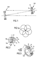
- Fig. 1 das Drehspiegelsystem in einer schematischen Seitenansicht als Kreiselsystem in sehr vergrößerter Darstellung;
- Fig. 1a eine schematische Draufsicht auf die Bewegungslinien des Drehspiegelsystems gemäß Fig. 1;
- Fig. 2 die Keilplatten des Drehspiegels in Explorationsdarstellung, in vergrößertem maßstab perspektivisch gezeichnet;
- Fig. 3 in einer perspektivischen, vergrößerten Darstellung eine Draufsicht auf einen Drehspiegel in seiner Fassung.
- Wie aus den Figuren 1 bis 3 ersichtlich, setzt sich die Scaneinrichtung in dem gezeigten Ausführungsbeispiel aus speziell ausgebildeten Zylinderspiegeln 100, 100′ zusammen, die als Zylinderkörper 10, 11 ausgebildet sind, die sich um ihre Hauptachse 14 drehen, wobei sie innerhalb der Fassung 13 auf Luftlagern ruhen und durch Luftströmung in Rotation versetzt werden. Der Luftstrom ist also sowohl Antrieb als auch Lagerung. Damit aber diese Zylinderkörper 10, 11 optisch überhaupt eine Wirkung haben, sind sie nicht an ihrer Oberfläche verspiegelt, sondern die Spiegelschicht 12 läuft "schräg" durch den Zylinderspiegel 100, 100′ hindurch. Das heißt, der Zylinderspiegel ist aus zwei gleichen Zylinderkörpern 10, 11 zusammengesetzt, zwischen denen eine Spiegelschicht 12 angeordnet ist, die jedoch nicht senkrecht zur Rotationsachse steht, sondern in einem kleinen Winkel α, der je nach Erfordernis etc. zwischen 0,2° bis etwa 2° aus der Senkrechten abweicht. Dies wird dadurch erreicht, daß - wie auch deutlich aus der Fig. 2 entnehmbar ist - die mit der Spiegelschicht zu versehende Stirnfläche 10b, 11b um den gewünschten Winkelbetrag α aus der Parallelität zur Stirnfläche 10a, 11a abweicht, so daß "keilförmige Zylinderkörper" 10, 11 entstehen. Diese werden mit der Spiegelschicht so aneinandergefügt - vorzugsweise miteinander verklebt - daß ein "ebener" Zylinderspiegel 100 entsteht, die Achse 14 also nicht abgewinkelt wird. Der Zylinderspiegel 100, 100′ ist also aus zwei vollkommen gleichen Teilen aufgebaut, die miteinander verklebt sind. Diese beiden Teile - als Zylinderkörper 10, 11 bezeichnet - sind oberflächenverspiegelt. Die Zylinderspiegel 100, 100′ sind in ihren Abmaßen relativ sehr klein, im gezeigten Ausführungsbeispiel der Fig. 1 wird beispielsweise die Höhe zwischen 7mm und 5mm liegen.
- Diese Zylinderkörper 10, 11 sind nun in einer Fassung 13 auf Luftlagern angeordnet und werden durch Luftanströmung in Rotation versetzt. Aufgrund der geringen Abmaße und des geringen Gewichts der Zylinderspiegel 100, 100′ können diese außergewöhnlich hohe Winkelgeschwindigkeiten, die nahe der Materialzerreißgrenze liegen, aufnehmen. Im gezeigten Ausführungsbeispiel sind ca. 1 Million Umdrehungen pro Minute möglich. Zur Ausnützung des Luftstromes um optimale Umdrehungszahlen zu erreichen wird die Fassung mit Windangriffsflächen, Windschaufeln, Windgruben usw. - also mit Ausbildungen der bekannten Kreiseltechnik versehen.
- Bei der Drehung des zusammengefügten Zylinderspiegels 100 "torkelt" also die in ihm eingechlossene Spiegelfläche 12 und da, im vorliegenden Falle der Laserstrahl im nicht aufgeweiteten Zustand nur einen Durchmesser von weniger als 3mm besitzt, genügt es, wenn der Zylinderspiegel einen Durchmesser von 3mm hat. Ein so kleiner Zylinder läßt sich - wie bereits erwähnt - ohne weiteres auf Geschwindigkeiten von etwa 1 Million Umdrehungen pro Minute bringen. Die torkelnde Spiegelfläche 12, die jetzt nur aus ein paar Atomlagen besteht, ist nicht in der Lage, eine wesentliche Umwucht zu erzeugen. Der Laserstrahl wird damit auf einer kreisförmigen Bahn abgelenkt. Um nun zu einem Scanmuster zu kommen, muß mit einem zweiten Spiegel 100′ gearbeitet werden, der ebenfalls den Laserstrahl auf einer kreisförmigen Bahn ablenkt. Sind beide Spiegelfrequenzen nun nicht gleich groß, so kommt es zu einem räumlichen Muster, beispielsweise wie in Fig. 2 dargestellt. Der zweite Spiegel kann wesentlich langsamer laufen als der erste, muß aber einen größeren Durchmesser besitzen, falls nicht eine Konversionsoptik verwendet wird.
- Für den Anwendungsfall bei einer Lenkgranate entsteht das in Fig. 2 gezeigte Beispiel eines spiralförmigen Abtastmusters. Die Spirale wird einmal von innen nach außen und dann von außen nach innen durchlaufen.
Claims (5)
Applications Claiming Priority (2)
| Application Number | Priority Date | Filing Date | Title |
|---|---|---|---|
| DE3537843 | 1985-10-24 | ||
| DE19853537843 DE3537843A1 (de) | 1985-10-24 | 1985-10-24 | Schnelle scanneinrichtung fuer hoechste ablenkgeschwindigkeiten |
Publications (3)
| Publication Number | Publication Date |
|---|---|
| EP0219620A2 true EP0219620A2 (de) | 1987-04-29 |
| EP0219620A3 EP0219620A3 (en) | 1989-05-10 |
| EP0219620B1 EP0219620B1 (de) | 1992-03-25 |
Family
ID=6284354
Family Applications (1)
| Application Number | Title | Priority Date | Filing Date |
|---|---|---|---|
| EP86110213A Expired - Lifetime EP0219620B1 (de) | 1985-10-24 | 1986-07-24 | Schnelle Scanneinrichtung für höchste Ablenkgeschwindigkeiten |
Country Status (3)
| Country | Link |
|---|---|
| US (1) | US4717224A (de) |
| EP (1) | EP0219620B1 (de) |
| DE (1) | DE3537843A1 (de) |
Cited By (1)
| Publication number | Priority date | Publication date | Assignee | Title |
|---|---|---|---|---|
| WO2000033120A1 (de) * | 1998-11-30 | 2000-06-08 | Universität Hannover | Vorrichtung zum abtasten eines objektes |
Families Citing this family (5)
| Publication number | Priority date | Publication date | Assignee | Title |
|---|---|---|---|---|
| US5481392A (en) * | 1993-12-21 | 1996-01-02 | Minnesota Mining And Manufacturing Company | Axial mirror scanner system and method |
| US6483595B1 (en) | 2000-07-22 | 2002-11-19 | Basis Software, Inc. | Three dimensional optical scanner |
| US7037005B2 (en) * | 2004-03-29 | 2006-05-02 | Northrop Grumman Corporation | Pan and tilt apparatus using achromatic prisms |
| US9234989B1 (en) * | 2010-09-02 | 2016-01-12 | Lockheed Martin Corporation | Robustly mounted, single DOF, adjustable mirror |
| US10175344B2 (en) * | 2015-12-08 | 2019-01-08 | The Boeing Company | Light detection and ranging (LIDAR) scanning systems and methods |
Family Cites Families (12)
| Publication number | Priority date | Publication date | Assignee | Title |
|---|---|---|---|---|
| US1647631A (en) * | 1927-11-01 | Optical system | ||
| US3226721A (en) * | 1948-03-26 | 1965-12-28 | Sperry Rand Corp | Scanning antenna utilizing four rotary prisms to produce rectilinear scan and fifth rotary prism to produce conical scan |
| US2975668A (en) * | 1957-07-01 | 1961-03-21 | Lockheed Aircraft Corp | Optical scanning device |
| US2928952A (en) * | 1958-08-20 | 1960-03-15 | Curtis Lab Inc | Optical scanning system |
| GB1171102A (en) * | 1966-03-16 | 1969-11-19 | Nat Res Dev | Improvements in Pulsed Laser Systems. |
| DE1282675B (de) * | 1967-03-21 | 1968-11-14 | Eltro G M B H & Co Ges Fuer St | Vorrichtung zur sinusfoermigen Ablenkung eines Strahlenbuendels mittels Spiegel |
| DE1803609B2 (de) * | 1968-10-17 | 1971-07-15 | Vorrichtung zum zeilenversatz bei opto elektronischen abtast geraeten | |
| US3720454A (en) * | 1971-05-14 | 1973-03-13 | Avco Corp | Optical field curvature corrector |
| US4131916A (en) * | 1975-12-31 | 1978-12-26 | Logetronics, Inc. | Pneumatically actuated image scanning reader/writer |
| US4039246A (en) * | 1976-01-22 | 1977-08-02 | General Dynamics Corporation | Optical scanning apparatus with two mirrors rotatable about a common axis |
| US4436260A (en) * | 1981-12-21 | 1984-03-13 | The United States Of America As Represented By The Secretary Of The Air Force | Optical scanner for use in confined areas |
| DE3310875A1 (de) * | 1983-03-25 | 1984-09-27 | Robert Bosch Gmbh, 7000 Stuttgart | Strahlablenksystem |
-
1985
- 1985-10-24 DE DE19853537843 patent/DE3537843A1/de active Granted
-
1986
- 1986-07-24 EP EP86110213A patent/EP0219620B1/de not_active Expired - Lifetime
- 1986-10-24 US US06/923,003 patent/US4717224A/en not_active Expired - Fee Related
Cited By (2)
| Publication number | Priority date | Publication date | Assignee | Title |
|---|---|---|---|---|
| WO2000033120A1 (de) * | 1998-11-30 | 2000-06-08 | Universität Hannover | Vorrichtung zum abtasten eines objektes |
| US6583914B1 (en) | 1998-11-30 | 2003-06-24 | Universitat Hannover | Device for scanning an object |
Also Published As
| Publication number | Publication date |
|---|---|
| DE3537843C2 (de) | 1987-10-01 |
| EP0219620B1 (de) | 1992-03-25 |
| EP0219620A3 (en) | 1989-05-10 |
| US4717224A (en) | 1988-01-05 |
| DE3537843A1 (de) | 1987-04-30 |
Similar Documents
| Publication | Publication Date | Title |
|---|---|---|
| EP0219620B1 (de) | Schnelle Scanneinrichtung für höchste Ablenkgeschwindigkeiten | |
| DE2330153A1 (de) | Optisches instrument | |
| DE4029187C2 (de) | Längsgeströmter CO¶2¶-Laser | |
| DE2933222A1 (de) | Abnehmbare visiervorrichtung fuer ueberwachungskameras | |
| DE4235165C2 (de) | Optischer Strahlteiler, insbesondere für einen Laserstrahl | |
| DE1093188B (de) | Verfahren und Vorrichtung zur Herstellung von Filterelementen aus Papier | |
| DE1673899A1 (de) | Gasgelagerter Kreisel | |
| DE2115163C3 (de) | Dynamisch abstimmbares Federkardangelenk | |
| EP0414829A1 (de) | Vorrichtung zur gleichzeitigen berührungslosen prüfung einer mehrzahl von stellen eines prüfguts sowie deren verwendung. | |
| DE69120191T2 (de) | Dynamische Drucklagervorrichtung | |
| DE2453969C2 (de) | Vorrichtung zum aerodynamischen Stabilisieren der Lage eines rotierenden Aufzeichnungsträgers | |
| DE2643174A1 (de) | Optische vorrichtung mit den strahlengang durchquerenden, mechanischen verbindungsmitteln | |
| DE2237247C3 (de) | Schwungrad | |
| DE2533347A1 (de) | Magnetisches buendelablenksystem | |
| DE102012025493A1 (de) | Präzisionshalterung | |
| DE2215076A1 (de) | Einrichtung zur ablenkung eines aufzeichnungs- oder lesestrahls | |
| DE1547344B2 (de) | Elektro-optische abtastvorrichtung | |
| DE2521251C3 (de) | Hinweissäule | |
| DE4140032C2 (de) | Polygonspiegel und Polygonspiegelbaugruppe | |
| DE2623914C3 (de) | Auffächerbarer Farbtonblock | |
| DD285760A5 (de) | Vorrichtung zum beruehrungsfreien abstuetzen und umlenken von materialbahnen | |
| EP0283717A2 (de) | Optisch-mechanische Einrichtung | |
| DE2557989A1 (de) | Anlage mit rohrturbine oder rohrpumpe, deren laufrad feststehende schaufeln aufweist | |
| DE3873735T2 (de) | Piezoelektrisch erregte mechanische schwingeinrichtung und deren anwendung bei einem laserkreisel. | |
| DD248440A1 (de) | Optischer lentikularkegel |
Legal Events
| Date | Code | Title | Description |
|---|---|---|---|
| PUAI | Public reference made under article 153(3) epc to a published international application that has entered the european phase |
Free format text: ORIGINAL CODE: 0009012 |
|
| AK | Designated contracting states |
Kind code of ref document: A2 Designated state(s): CH DE FR IT LI SE |
|
| PUAL | Search report despatched |
Free format text: ORIGINAL CODE: 0009013 |
|
| AK | Designated contracting states |
Kind code of ref document: A3 Designated state(s): CH DE FR IT LI SE |
|
| 17P | Request for examination filed |
Effective date: 19890410 |
|
| 17Q | First examination report despatched |
Effective date: 19910621 |
|
| RBV | Designated contracting states (corrected) |
Designated state(s): CH FR IT LI SE |
|
| REG | Reference to a national code |
Ref country code: DE Ref legal event code: 8566 |
|
| GRAA | (expected) grant |
Free format text: ORIGINAL CODE: 0009210 |
|
| AK | Designated contracting states |
Kind code of ref document: B1 Designated state(s): CH FR IT LI SE |
|
| ET | Fr: translation filed | ||
| ITF | It: translation for a ep patent filed | ||
| PGFP | Annual fee paid to national office [announced via postgrant information from national office to epo] |
Ref country code: FR Payment date: 19920707 Year of fee payment: 7 |
|
| PGFP | Annual fee paid to national office [announced via postgrant information from national office to epo] |
Ref country code: SE Payment date: 19920715 Year of fee payment: 7 |
|
| PGFP | Annual fee paid to national office [announced via postgrant information from national office to epo] |
Ref country code: CH Payment date: 19920910 Year of fee payment: 7 |
|
| PLBE | No opposition filed within time limit |
Free format text: ORIGINAL CODE: 0009261 |
|
| STAA | Information on the status of an ep patent application or granted ep patent |
Free format text: STATUS: NO OPPOSITION FILED WITHIN TIME LIMIT |
|
| 26N | No opposition filed | ||
| PG25 | Lapsed in a contracting state [announced via postgrant information from national office to epo] |
Ref country code: SE Effective date: 19930725 |
|
| PG25 | Lapsed in a contracting state [announced via postgrant information from national office to epo] |
Ref country code: LI Effective date: 19930731 Ref country code: CH Effective date: 19930731 |
|
| PG25 | Lapsed in a contracting state [announced via postgrant information from national office to epo] |
Ref country code: FR Effective date: 19940331 |
|
| REG | Reference to a national code |
Ref country code: CH Ref legal event code: PL |
|
| REG | Reference to a national code |
Ref country code: FR Ref legal event code: ST |
|
| EUG | Se: european patent has lapsed |
Ref document number: 86110213.5 Effective date: 19940210 |
|
| PG25 | Lapsed in a contracting state [announced via postgrant information from national office to epo] |
Ref country code: IT Free format text: LAPSE BECAUSE OF NON-PAYMENT OF DUE FEES;WARNING: LAPSES OF ITALIAN PATENTS WITH EFFECTIVE DATE BEFORE 2007 MAY HAVE OCCURRED AT ANY TIME BEFORE 2007. THE CORRECT EFFECTIVE DATE MAY BE DIFFERENT FROM THE ONE RECORDED. Effective date: 20050724 |