EP0219003A2 - Partition, especially a screen-type partition - Google Patents
Partition, especially a screen-type partition Download PDFInfo
- Publication number
- EP0219003A2 EP0219003A2 EP86113592A EP86113592A EP0219003A2 EP 0219003 A2 EP0219003 A2 EP 0219003A2 EP 86113592 A EP86113592 A EP 86113592A EP 86113592 A EP86113592 A EP 86113592A EP 0219003 A2 EP0219003 A2 EP 0219003A2
- Authority
- EP
- European Patent Office
- Prior art keywords
- partition
- elements
- partition according
- tension
- tension element
- Prior art date
- Legal status (The legal status is an assumption and is not a legal conclusion. Google has not performed a legal analysis and makes no representation as to the accuracy of the status listed.)
- Granted
Links
- 238000005192 partition Methods 0.000 title claims abstract description 81
- 239000011358 absorbing material Substances 0.000 claims description 6
- 239000002184 metal Substances 0.000 claims description 6
- 238000006073 displacement reaction Methods 0.000 claims description 3
- 230000000149 penetrating effect Effects 0.000 claims description 2
- 239000000758 substrate Substances 0.000 claims 1
- 230000008878 coupling Effects 0.000 abstract 4
- 238000010168 coupling process Methods 0.000 abstract 4
- 238000005859 coupling reaction Methods 0.000 abstract 4
- 238000004873 anchoring Methods 0.000 description 6
- 230000000694 effects Effects 0.000 description 5
- 238000010521 absorption reaction Methods 0.000 description 2
- 230000006978 adaptation Effects 0.000 description 2
- 239000000463 material Substances 0.000 description 2
- 230000002349 favourable effect Effects 0.000 description 1
- 238000004519 manufacturing process Methods 0.000 description 1
- 230000035515 penetration Effects 0.000 description 1
- 230000006641 stabilisation Effects 0.000 description 1
- 238000011105 stabilization Methods 0.000 description 1
- 230000000152 swallowing effect Effects 0.000 description 1
Images


Classifications
-
- E—FIXED CONSTRUCTIONS
- E04—BUILDING
- E04B—GENERAL BUILDING CONSTRUCTIONS; WALLS, e.g. PARTITIONS; ROOFS; FLOORS; CEILINGS; INSULATION OR OTHER PROTECTION OF BUILDINGS
- E04B2/00—Walls, e.g. partitions, for buildings; Wall construction with regard to insulation; Connections specially adapted to walls
- E04B2/74—Removable non-load-bearing partitions; Partitions with a free upper edge
Definitions
- the invention relates to a partition, in particular a partition made of preferably sound-absorbing material, an intermediate space to the ceiling or floor being optionally left above and / or below the partition.
- a sound-absorbing partition element which consists of a frame and cover plates attached to it on both sides and elastic intermediate layers between the frame and cover plates.
- This partition element is intended for hanging, so that it can only be attached at very specific points. Furthermore, its surface is rigid and therefore cannot be adapted to different spatial conditions.
- Moving walls with feet are also known from practice, which are used to subdivide open-plan offices and the like.
- the surface shape of these partition walls is largely determined, so that adaptation to different space conditions is only possible by different means large partition walls is possible.
- the invention has for its object to provide a partition or partition of the type mentioned, which allows a good adaptation of its surface to different spaces and still has good inherent stability.
- a partition of the type mentioned is characterized in that it is formed from rod-shaped elements touching over their position and that the rod-shaped elements have transverse openings and a tension element running through them, which is anchored tensile to the two end pieces of the partition is.
- This partition or partition can thus be curved without losing its stability or sound-absorbing properties.
- the tension element and the rod-shaped elements lined up on it enable a corresponding deformation transversely to the course of the individual elements, without gaps and breakthroughs occurring between these elements.
- the production is relatively simple, since no frames and rigid shells with an intermediate layer have to be carefully connected to one another, but individual rod-shaped elements, preferably with sound-absorbing material, must be lined up on a tension element, as a result of which the partition wall is essentially formed.
- a very particularly advantageous and expedient embodiment of the invention of considerable importance can consist in the fact that the tension element is a band spring, preferably with an approximately rectangular or elongated cross section, which is oriented in the axial direction of the elements.
- the tension element is a band spring, preferably with an approximately rectangular or elongated cross section, which is oriented in the axial direction of the elements. This results not only in the possibility of curving the surface of the partition wall in that the tension element can be curved as desired in the direction of its spring action, but in the longitudinal direction of the elements an additional stiffening effect is generated by this tension element. This increases the stability of the entire partition, in particular when the rod-shaped elements are oriented vertically. It is useful if the tension element is a band spring made of metal.
- a tension element can be provided in the upper and lower edge region of the partition and, if appropriate, in the central region if the height of the partition makes it appear necessary.
- the sound-absorbing elements are column-shaped and the tension elements run through their cross-sectional centers.
- a core rod or similar support element running over its length and provided with transverse slots for the tension element, on the outside of which a sound-absorbing layer is arranged. Weight can be saved if the core rod is designed as a support tube.
- a pressure screw or the like which, in the area of the slot and the passage of the tension element through the support tube, preferably acts on the tension element on a narrow side and fixes it in a force-fitting manner. This can support the mutual holding of the lined-up elements and prevent individual elements from being pressed together because of the relatively soft upper side and gaps between other elements.
- a further adaptability of the partition wall can be given in that the support tube of the sound absorbing elements has a plurality of passage slots for the pulling element next to one another in height, so that adjacent sound absorbing elements can be threaded on the pulling element offset in height.
- the ends of the tension elements can be connected, in particular riveted, to an anchor part, preferably to an armature having legs projecting from them on two sides, and the anchor part can preferably engage in a hollow profile which lies against the outermost element.
- the anchoring of the tension element is covered.
- the hollow profile can have or form at least one connection for connecting to the hollow profile of a neighboring partition. It thus has a double function in that it forms an elegant end to the partition wall and at the same time enables attachment to a neighboring partition wall to put together several such walls.
- the hollow profile is open on its contact side to the partition and has undercuts as inner stops for the legs of the anchor part at its edges touching the last element of the sound-absorbing elements lined up on the tension element.
- the ends of the legs of the armature projecting transversely to the tension element can at their ends against the last sound-absorbing element must be bent and these bent areas can be supported with their end faces on the inside of the undercuts of the hollow profile.
- a partition which can preferably be used as a partition, the surface of which can also be adapted in a favorable manner to angular space conditions, in addition to which an easy connection to other such or other rigid partition walls is possible, at the same time the this deformation enables rod-shaped sound-absorbing elements in conjunction with the traction elements passing through them to enable the aforementioned deformation in a simple manner and without impairing their sound-absorbing properties and even support the sound-absorbing effect due to the fissuring of the surface formed by their shape.
- a partition designated as a whole by 1 is embodied in the exemplary embodiment as a partition which leaves a space 2 above and below it to the ceiling or floor 3.
- This partition wall 1 is formed from rod-shaped elements 4 touching over its length and, according to FIGS. 2 and 5, these rod-shaped elements 4 have transverse openings 5 and a pulling element 6 running through them, which at the two end pieces 7 of the partition wall 1 is still tight is descriptively anchored.
- the tension element 6 is a band spring with an approximately rectangular or elongated cross section, which cross section is arranged in the direction of the elements 4.
- the individual rod-shaped elements 4 are fixed against displacement on the tension element 6 in its orientation direction at least by mutual contact. These elements 4 are arranged vertically in the exemplary embodiment.
- the tension element 6 is preferably a band spring made of metal, which has a correspondingly high strength.
- the sound absorbing elements 4 are 2 and 5 are columnar or cylindrical, touch along surface lines and the tension elements 6 run through their cross-sectional centers, so that a deformation of the entire wall 1 is possible on two sides.
- FIGS. 2 and 5 it is shown that in the interior of the elements 4 there is a core rod or the like which runs over its length and is provided with transverse slots 8 for the respective tension element 6 and which is designed as a support tube 9 in the exemplary embodiment and attached the outside of which a sound-absorbing layer 10 is optionally arranged with an outer cover jacket 11.
- a core rod or the like which runs over its length and is provided with transverse slots 8 for the respective tension element 6 and which is designed as a support tube 9 in the exemplary embodiment and attached the outside of which a sound-absorbing layer 10 is optionally arranged with an outer cover jacket 11.
- a pressure screw or the like can be provided, which preferably pulls the pulling element 6 in the area of the slot 8 and the penetration of the pulling element 6 through the support tube 9 can act on a narrow side and fix non-positively. This can prevent the elements 4, which are relatively soft and resilient on their upper side, from being displaced on the tension elements and thus gaps being formed in the partition wall 1. In the case of elements 4 with a smaller cross section, such additional fastening of the elements 4 is generally not necessary, but is also possible.
- guides 11 penetrating the openings 8 of the sound-absorbing elements 4 and the sound-absorbing layer 10 are preferably made of plastic for the tension element. This improves the stabilization on the tension element, so that the individual elements 4 automatically receive their exact vertical alignment next to one another.
- Fig. 2 it can be seen, also in connection with Fig. 1, that at the support tubes 9 or the like. At least two elements 4, preferably elements 4 located on the edge of the partition 1, are attacked by extensions 12 with adjustable feet 13 can. The extensions 12 can be screwed or clamped into the support tubes 9, for example.
- the adjustable feet 13 have a metal insert 14 to increase their weight and thus also the friction with respect to the base 3 and can additionally be roughened on their underside 15. As a result, they can counteract the restoring forces of the spring-shaped tension elements 6 even when the entire partition 1 is strongly curved. Additional measures for fixing the set curvature of the partition 1 are therefore unnecessary.
- the anchoring of the tension element 6 selected in the exemplary embodiment can be seen on the two end pieces 7 of the partition 1. It is provided that the ends of the tension elements 6 with an anchor part 16, in Embodiment with an armature 16 projecting from two sides of the pulling element 6 and connected with rivets 16.
- the armature part 16 engages with its legs 17 in a hollow profile forming the end pieces 7, which lies against the outermost element 4.
- This hollow profile can have or form at least one connection, not shown in the drawing, for connection to the corresponding hollow profile of a neighboring partition 1, so that several partition walls 1 according to the invention can be put together and connected.
- the hollow profile thus has a double function for connecting and as end piece 7.
- the hollow profile is open on its contact side to the partition 1 and its last element 4 and has 18 undercuts 19 on its edges touching this last element 4 as internal stops for the legs 17 of the anchor part 16.
- the ends 20 of the leg 17 of the armature 16 projecting transversely to the tension element 6 are bent towards the last element 4 and are supported with their end faces on the inside of the undercuts 19 of the hollow profile or of the end piece 7 .
- the tensile forces can be formed by the fact that all the elements 4 lie somewhat against one another under pressure, so that they are somewhat compressed and their restoring forces act as tensile forces on the tensile elements 6.
Landscapes
- Engineering & Computer Science (AREA)
- Architecture (AREA)
- Physics & Mathematics (AREA)
- Electromagnetism (AREA)
- Civil Engineering (AREA)
- Structural Engineering (AREA)
- Building Environments (AREA)
- Devices Affording Protection Of Roads Or Walls For Sound Insulation (AREA)
- Agricultural Chemicals And Associated Chemicals (AREA)
- External Artificial Organs (AREA)
- Floor Finish (AREA)
Abstract
Description
Die Erfindung betrifft eine Trennwand, insbesondere Stellwand aus vorzugsweise schallschluckendem Werkstoff, wobei gegebenenfalls über und/oder unter der Trennwand ein Zwischenraum zur Raumdecke bzw. zum Raumboden frei bleibt.The invention relates to a partition, in particular a partition made of preferably sound-absorbing material, an intermediate space to the ceiling or floor being optionally left above and / or below the partition.
Aus der DE-PS 2o 49 836 ist beispielsweise ein schalldämmendes Trennwandelement bekannt, welches aus einem Rahmen und beidseits daran befestigten Deckplatten sowie elastischen Zwischenlagen zwischen Rahmen und Deckplatten besteht. Dieses Trennwandelement ist zum Aufhängen vorgesehen, so daß es nur an ganz bestimmten Stellen angebracht werden kann. Darüberhinaus ist es hinsichtlich seiner Oberfläche starr und somit nicht an unterschiedliche Platzverhältnisse anpaßbar.From DE-PS 2o 49 836, for example, a sound-absorbing partition element is known, which consists of a frame and cover plates attached to it on both sides and elastic intermediate layers between the frame and cover plates. This partition element is intended for hanging, so that it can only be attached at very specific points. Furthermore, its surface is rigid and therefore cannot be adapted to different spatial conditions.
Aus der Praxis sind ferner Stellwände mit Füßen bekannt, die zur Unterteilung von Großraumbüros und dgl. dienen. Auch dabei ist die Oberflächenform dieser Stellwände weitestgehend festgelegt, so daß eine Anpassung an unterschiedliche Platzverhältnisse nur durch unterschiedlich große Stellwände möglich ist.Moving walls with feet are also known from practice, which are used to subdivide open-plan offices and the like. Here, too, the surface shape of these partition walls is largely determined, so that adaptation to different space conditions is only possible by different means large partition walls is possible.
Der Erfindung liegt die Aufgabe zugrunde, eine Trennwand oder Stellwand der eingangs erwähnten Art zu schaffen, die eine gute Anpassung ihrer Oberfläche an unterschiedliche Platzverhältnisse ermöglicht und dennoch eine gute Eigenstabilität hat.The invention has for its object to provide a partition or partition of the type mentioned, which allows a good adaptation of its surface to different spaces and still has good inherent stability.
Zur Lösung dieser Aufgabe ist eine Trennwand der eingangs erwähnten Art dadurch gekennzeichnet, daß sie aus sich über ihre Lage berührenden stabförmigen Elementen gebildet ist und daß die stabförmigen Elemente Queröffnungen und ein durch diese hindurch verlaufendes Zugelement aufweisen, welches an den beiden Endstücken der Stellwand zugfest verankert ist. Somit kann diese Trenn- oder Stellwand gekrümmt werden, ohne ihre Stabilität oder ihre schallschluckende Eigenschaft zu verlieren. Das Zugelement und die stabförmigen, darauf aufgereihten Elemente ermöglichen eine entsprechende Verformung quer zum Verlauf der einzelnen Elemente, ohne daß dabei Lücken und Durchbrüche zwischen diesen Elementen auftreten können. Gleichzeitig ist die Herstellung relativ einfach, da keine Rahmen und starren Schalen mit Zwischenschicht sorgfältig miteinander verbunden werden müssen, sondern einzelne stabförmige Elemente mit vorzugsweise schallschluckendem Werkstoff auf einem Zugelement aufzureihen sind, wodurch die Trennwand bereits im wesentlichen gebildet ist.To solve this problem, a partition of the type mentioned is characterized in that it is formed from rod-shaped elements touching over their position and that the rod-shaped elements have transverse openings and a tension element running through them, which is anchored tensile to the two end pieces of the partition is. This partition or partition can thus be curved without losing its stability or sound-absorbing properties. The tension element and the rod-shaped elements lined up on it enable a corresponding deformation transversely to the course of the individual elements, without gaps and breakthroughs occurring between these elements. At the same time, the production is relatively simple, since no frames and rigid shells with an intermediate layer have to be carefully connected to one another, but individual rod-shaped elements, preferably with sound-absorbing material, must be lined up on a tension element, as a result of which the partition wall is essentially formed.
Dabei ist es zweckmäßig, wenn die einzelnen stabförmigen Elemente gegen Verschiebungen auf dem Zugelement in dessen Orientierungsrichtung durch gegenseitige Berührung festgelegt sind. Somit ergibt sich einerseits eine dichte Trennwand, bei der andererseits die gegenseitige Festlegung der einzelnen Elemente sehr einfach ist.It is expedient if the individual rod-shaped elements are fixed against displacement on the tension element in its direction of orientation by mutual contact. This results on the one hand in a sealed partition, on the other hand, the mutual determination of the individual elements is very simple.
Ein ganz besonders vorteilhafte und zweckmäßige Ausbildung der Erfindung von erheblicher Bedeutung kann darin bestehen, daß das Zugelement eine Bandfeder vorzugsweise mit einem etwa rechteckigen oder länglichen Querschnitt ist, der in Achsrichtung der Elemente orientiert ist. Dadurch ergibt sich nicht nur die Möglichkeit, die Oberfläche der Trennwand dadurch krümmen, daß das Zugelement in Richtung seiner Federwirkung beliebig gekrümmt werden kann, sondern in Längsrichtung der Elemente wird zusätzlich von diesem Zugelement eine aussteifende Wirkung erzeugt. Dies erhöht die Stabilität der gesamten Trennwand insbesondere dann, wenn die stabförmigen Elemente vertikal orientiert sind. Dabei ist es zweckmäßig, wenn das Zugelement eine Bandfeder aus Metall ist. Diese ist einerseits relativ preiswert, 3ndererseits aber stabil und von hoher Zugfestigkeit, so daß die Trennwand durch dieses sie durchsetzende Zugelement stabilisiert ist und dennoch beliebig gekrümmt oder auch gerade ausgerichtet werden kann. Dabei kann im oberen und unteren Randbereich der Trennwand und gegebenenfalls im Mittelbereich jeweils ein Zugelement vorgesehen sein, falls es die Höhe der Trennwand erforderlich erscheinen läßt.A very particularly advantageous and expedient embodiment of the invention of considerable importance can consist in the fact that the tension element is a band spring, preferably with an approximately rectangular or elongated cross section, which is oriented in the axial direction of the elements. This results not only in the possibility of curving the surface of the partition wall in that the tension element can be curved as desired in the direction of its spring action, but in the longitudinal direction of the elements an additional stiffening effect is generated by this tension element. This increases the stability of the entire partition, in particular when the rod-shaped elements are oriented vertically. It is useful if the tension element is a band spring made of metal. This is both relatively inexpensive, 3, so that the partition wall it is stabilized ndererseits but stable and of high tensile strength by passing through this tension member, and yet can be arbitrarily curved or straight. In this case, a tension element can be provided in the upper and lower edge region of the partition and, if appropriate, in the central region if the height of the partition makes it appear necessary.
Besonders zweckmäßig ist es, wenn die Schallschluckelemente säulenförmig ausgebildet sind und die Zugelemente durch ihre Querschnittsmitten verlaufen. An den Säulenoberflächen ergibt sich dann zusätzlich eine Schallbrechung, die die Wirkung des schallschluckenden Werkstoffes unterstützt. Dies ergibt sich vor allem dann, wenn die Elemente etwa zylindrisch sind und sich entlang von Mantellinien berühren. Dies hat den weiteren Vorteil, daß beim Krümmen der Trennwand die zylinderischen Elemente sich mit ihren Oberflächen etwas aufeinander abwälzen können, wobei gleichzeitig eine gewisse Nachgiebigkeit des schallschluckenden Oberflächenwerkstoffes diese Verformung erleichtert. Für eine gute Stabilität und Festigkeit der Tennwand ist es vorteilhaft, wenn im Inneren der Elemente jeweils ein über ihre Länge verlaufender, mit Querschlitzen für das Zugelement versehener Kernstab od. dgl. Tragelement vorgesehen ist, an dessen Außenseite eine schallschluckende Schicht angeordnet ist. Dabei kann Gewicht gespart werden, wenn der Kernstab als Tragrohr ausgebildet ist.It is particularly expedient if the sound-absorbing elements are column-shaped and the tension elements run through their cross-sectional centers. In addition, there is a sound refraction on the column surfaces, which supports the effect of the sound-absorbing material. This is especially the case when the elements are roughly cylindrical and touch along surface lines. This has the further advantage that when the partition wall is curved, the cylindrical elements can roll somewhat over one another with their surfaces, a ge simultaneously Known resilience of the sound-absorbing surface material facilitates this deformation. For good stability and strength of the partition wall, it is advantageous if in the interior of the elements there is provided a core rod or similar support element running over its length and provided with transverse slots for the tension element, on the outside of which a sound-absorbing layer is arranged. Weight can be saved if the core rod is designed as a support tube.
Vor allem für im Querschnitt relativ große Elemente kann es vorteilhaft sein, wenn eine Druckschraube od. dgl. vorgesehen ist, die im Bereich des Schlitzes und des Durchtrittes des Zugelementes durch das Tragrohr das Zugelement vorzugsweise an einer Schmalseite beaufschlagt und kraftschlüssig festlegt. Dies kann die gegenseitige Halterung der aufgereihten Elemente unterstützen und verhindern, daß einzelne Elemente wegen der relativ weichen Oberseite zusammengedrückt werden und zwischen anderen Elementen Lücken entstehen.Especially for elements of relatively large cross-section, it can be advantageous if a pressure screw or the like is provided which, in the area of the slot and the passage of the tension element through the support tube, preferably acts on the tension element on a narrow side and fixes it in a force-fitting manner. This can support the mutual holding of the lined-up elements and prevent individual elements from being pressed together because of the relatively soft upper side and gaps between other elements.
An den Durchtrittsöffnungen der Schallschluckelemente können insbesondere bei größeren Querschnitten deren Wandungen durchsetzende Führungen vorzugsweise aus Kunststoff für das Zugelement vorgesehen scin. Dadurch werden die von dem Zugelement auch in vertikaler Richtung gehaltenen Schallschluckelemente besser über ihren gesamten Querschnitt abgestützt.At the passage openings of the sound-absorbing elements, in particular in the case of larger cross-sections, guides which pass through the walls, preferably made of plastic, can be provided for the tension element. As a result, the sound-absorbing elements held by the tension element in the vertical direction are better supported over their entire cross-section.
Für das einfache Aufstellen der Trennwand ist es zweckmäßig, wenn an den Tragrohren od. dgl. zumindest zweier Elemente, vorzugsweise von am Rand der Trennwand befindlichen Elementen, Fortsetzungen mit Stellfüßen angreifen. Dabei können die Stellfüße zur Uergrößerung ihres Gewichtes und der Reibung gegenüber dem Untergrund eine Metalleinlage aufweisen und/oder an ihrer Unterseite aufgerauht sein. Somit kann selbst bei einer starken Krümmung der Trennwand die dann von den federförmigen Zugelementen bewirkte Rückstellkraft gut aufgefangen werden.For the simple erection of the partition, it is expedient if extensions on the support tubes or the like. At least two elements, preferably elements located at the edge of the partition, engage with adjustable feet. The feet can increase their weight and friction against the ground Have metal insert and / or be roughened on its underside. Thus, even with a strong curvature of the partition, the restoring force then caused by the spring-like tension elements can be absorbed well.
Eine weitere Anpassbarkeit der Trennwand kann dadurch gegeben sein, daß das Tragrohr der Schallschluckelemente in der Höhe nebeneinander mehrere Durchtrittsschlitze für das Zugelement hat, so daß nebeneinanderliegende Schallschluckelemente in der Höhe gegeneinander versetzt auf das Zugelement aufgefädelt werden können.A further adaptability of the partition wall can be given in that the support tube of the sound absorbing elements has a plurality of passage slots for the pulling element next to one another in height, so that adjacent sound absorbing elements can be threaded on the pulling element offset in height.
Die Enden der Zugelemente können mit einem Ankerteil, vorzugsweise mit einem nach zwei Seiten von ihnen abstehende Schenkel aufweisenden Anker verbunden, insbesondere vernietet sein und das Ankerteil kann vorzugsweise in ein Hohlprofil eingreifen, welches am jeweils äußersten Element anliegt. Dadurch wird die Verankerung des Zugelementes verdeckt. Zusätzlich kann dabei das Hohlprofil wenigstens einen Anschluß zum Verbinden mit dem Hohlprofil einer Nachbar-Trennwand aufweisen oder bilden. Somit erhält es eine Doppelfunktion, in dem es einerseits einen formschönen Abschluß der Trennwand bildet und gleichzeitig das Anbringen an einer Nachbar-trennwand zur Zusammenstellung mehrerer solcher Wände ermöglicht.The ends of the tension elements can be connected, in particular riveted, to an anchor part, preferably to an armature having legs projecting from them on two sides, and the anchor part can preferably engage in a hollow profile which lies against the outermost element. As a result, the anchoring of the tension element is covered. In addition, the hollow profile can have or form at least one connection for connecting to the hollow profile of a neighboring partition. It thus has a double function in that it forms an elegant end to the partition wall and at the same time enables attachment to a neighboring partition wall to put together several such walls.
Zweckmäßig ist es dabei, wenn das Hohlprofil an seiner Berührseite zu der Trennwand offen ist und an seinen das letzte Element der auf das Zugelement aufgereihten schallschluckenden Elemente berührenden Rändern Hinterschneidungen als Innenanschläge für die Schenkel des Ankerteiles hat. Dabei können die Enden der quer zu dem Zugelement abstehenden Schenkel des Ankers an ihren Enden gegen das letzte schallschluckende Element hin abgebogen sein und diese abgebogenen Bereiche können sich mit ihren Stirnseiten an den Innenseiten der Hinterschneidungen des Hohlprofiles abstützen. Dies ergibt eine zugfeste und sichere Verankerung des Zugelementes, wobei die Zugkraft dadurch erzeugt sein kann, daß die an ihrer Oberseite aufgrund des schallschluckenden Werkstoffes etwesweichen Elemente unter leichtem Druck aneinander gelegt sind und ihre Rückstellkräfte sich zu der Zugkraft an den Ankern summieren. Dabei ist eine solche Berührung der einzelnen schallschluckenden Elemente unter Druck auch dann möglich, wenn der schallschluckende Werkstoff nocheinmal ummantelt ist.It is useful if the hollow profile is open on its contact side to the partition and has undercuts as inner stops for the legs of the anchor part at its edges touching the last element of the sound-absorbing elements lined up on the tension element. The ends of the legs of the armature projecting transversely to the tension element can at their ends against the last sound-absorbing element must be bent and these bent areas can be supported with their end faces on the inside of the undercuts of the hollow profile. This results in a tension-proof and secure anchoring of the tension element, the tension force being able to be generated in that the somewhat soft elements are placed against one another under light pressure due to the sound-absorbing material and their restoring forces add up to the tension force on the anchors. Such a contact of the individual sound-absorbing elements under pressure is also possible if the sound-absorbing material is covered again.
Vor allem bei Kombinationen der vorbeschriebenen Merkmale und Maßnahmen ergibt sich eine vorzugsweise als Stellwand verwendbare Trennwand, deren Oberfläche in günstiger Weise auch an winklige Platzverhältnisse angepaßt werden kann, wobei zusätzlich ein leichtes Verbinden mit weiteren derartigen oder auch anderen starren Trennwänden möglich ist, wobei gleichzeitig die diese Verformung ermöglichenden stabförmigen schallschluckenden Elemente in Uerbindung mit den sie durchsetzenden Zugelementen die erwähnte Verformung auf einfache Weise und ohne Beeinträchtigung ihrer schallschluckenden Eigenschaft ermöglichen und aufgrund der durch ihre Form gebildeten Zerklüftung der Oberfläche den Schallschluckeffekt sogar unterstützen.Especially with combinations of the features and measures described above, there is a partition which can preferably be used as a partition, the surface of which can also be adapted in a favorable manner to angular space conditions, in addition to which an easy connection to other such or other rigid partition walls is possible, at the same time the this deformation enables rod-shaped sound-absorbing elements in conjunction with the traction elements passing through them to enable the aforementioned deformation in a simple manner and without impairing their sound-absorbing properties and even support the sound-absorbing effect due to the fissuring of the surface formed by their shape.
Nachstehend ist die Erfindung mit ihren ihr als wesentlich zugehörenden Einzelheiten an Hand der Zeichnung noch näher beschrieben. Es zeigt in schematisierter Darstellung:
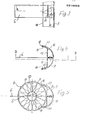
- Fig. 1 eine Ansicht einer Trennwand, die aus etwa zylinderischen vertikalen, sich längs mantellinienberührenden schallschluckenaen Elementen zusammengesetzt ist,
- Fig.2 in vergrößertem Maßstab einen Längsschnitt durch einen Teil einer erfinaungsgemäßen Trennwand mit Darstellung der bandfederförmigen Zugelemente, auf denen die zylinderischen, schallschlucken. Elemente aufgereiht sind,
- Fig.3 eine Seitenansicht und
- Fig.4 eine Draufsicht der Verankerung des die schallschluckenden Elemente tragenden federförmigen Zugelementes und
- Fig.5 im Querschnitt die Verbindung der Verankerung des Zugelementes mit dem letzten schallschluckenden Element einer Trennwand gem. Fig. 1 und 2.
- Fig. 1 is a view of a partition that from about cylindrical vertical sound-absorbing elements that come into contact along the surface line,
- 2 shows, on an enlarged scale, a longitudinal section through part of a partition according to the invention, showing the band-spring-shaped tension elements on which the cylindrical, sound-absorbing elements. Elements are lined up
- 3 shows a side view and
- 4 shows a plan view of the anchoring of the spring-like tension element carrying the sound-absorbing elements and
- 5 shows in cross section the connection of the anchoring of the tension element with the last sound-absorbing element of a partition according to 1 and 2.
Eine im ganzen mit 1 bezeichnete Trennwand ist im Ausführungsbeispiel als Stellwand ausgebildet, welche über und unter sich einen Zwischenraum 2 zur Raumdecke bzw. zum Raumboden 3 freiläßt.A partition designated as a whole by 1 is embodied in the exemplary embodiment as a partition which leaves a
Diese Trennwand 1 ist aus sich über ihre Länge berührenden stabförmigen Elementen 4 gebildet und gemäß den figuren 2 und 5 haben diese stabförmigen Elemente 4 Queröffnungen 5 und ein durch diese hindurch verlaufendes Zugelement 6, welches an den beiden Endstücken 7 der Trennwand 1 zugfest in noch zu beschreibender Weise verankert ist.This partition wall 1 is formed from rod-
In den Figuren 2 bis 5 erkennt man dabei deutlich, daß im Ausführungsbeispiel das Zugelement 6 eine Bandfeder mit einem etwa rechteckigen bzw. länglichen Querschnitt ist, welcher Querschnitt in Acnsrichtung oder Drientierungsrichtung der Elemente 4 angeordnet ist. Die einzelnen stabförmigen Elemente 4 sind dabei gegen Verschiebung auf dem Zugelement 6 in dessen Orientierungsrichtung zumindest durch gegenseitige Berührung festgelegt. Dabei sind diese Elemente 4 im Ausführungsbeispiel vertikal angeordnet. Das Zugelement 6 ist bevorzugt eine Bandfeder aus Metall, die entsprechend hohe Festigkeit hat.In Figures 2 to 5 you can clearly see that in the embodiment, the
Auf diese Weise ist es möglich, bei fest aneinander liegenden Einzelelementen 4 die Zugelemente 6, die im oberen und unteren Randbereich der Trennwand 1 und gem. Fig. 2 auch im Mittelbereich vorgesehen sind, zu biegen und somit der Trennwand 1 verschiedene Krümmungen zu geben, so daß sie an unterschiedliche Platzverhältnisse angepaßt werden kann. Dabei sind die Schallschluckelemente 4 gem. den Fig. 2 und 5 säulenförmig bzw. zylinderisch ausgebildet, berühren sich entlang von Mantellinien und die Zugelemente 6 verlaufen durch ihre Querschnittsmitten, so daß eine Verformung der gesamten Wand 1 nach zwei Seiten möglich ist.In this way, it is possible, in the case of
Selbst eine S-förmige Krümmung mit wechselnder Krümmungsrichtung kann so an der Stellwand 1 eingestellt werden.Even an S-shaped curvature with changing curvature can be set on the partition 1.
In den Figuren 2 und 5 ist dargestellt, daß im Inneren der Elemente 4 jeweils ein über ihre Länge verlaufender, mit Querschlitzen 8 für das jeweilige Zugelement 6 versehener Kernstab od. dgl. Tragelement vorgesehen ist,der im Ausführungsbeispiel als Tragrohr 9 ausgebildet ist und an dessen Außenseite eine schallschluckende Schicht 1o gegebenenfalls mit einem äußeren Abschlußmantel 11 angeordnet ist. Dies ergibt einen sehr einfachen Aufbau der einzelnen Elemente 4 und verleiht diesen eine gute schallschluckende Wirkung, die außerdem durch die Zerklüftung der Oberfläche unterstützt wird. Gleichzeitig wird die Montage dieser Elemente sehr einfach, da diese lediglich eines nach dem anderen auf den Zugelementen 6 aufgereiht werden müssen. Die Gewichtskräfte werden dabei von den Tragrohren 9 übertragen, während die Schallschluckwirkung von dem Werkstoff 1o erzeugt wird.In FIGS. 2 and 5 it is shown that in the interior of the
Es sei noch erwähnt, daß insbesondere für Elemente 4 mit wesentlich größerem Querschnitt und somit noch größerer Schallschluckwirkung jeweils eine Druckschraube od. dgl. vorgesehen sein kann, die im Bereich des Schlitzes 8 und des Durcntrittes des Zugelementes 6 durch das Tragrohr 9 das Zugelement 6 vorzugsweise an einer Schmalseite beaufschlagen und kraftschlüssig festlegen kann. Dadurch kann verhindert werden, daß die an ihrer Oberseite relativ weichen und nachgiebigen Elemente 4 auf den Zugelementen verschoben werden und somit Lücken in der Trennwand 1 gebildet werden. Bei Elementen 4 von geringerem Querschnitt ist in der Regel eine solche zusätzliche Befestigung der Elemente 4 nicht erforderlich, aber auch möglich.It should also be mentioned that in particular for
Ebenfalls für Elemente 4 größerer Querschnitte kann es zweckmäßig sein, wenn an den Durchtrittsöffnungen 8 der Schallschluckelemente 4 deren Wandungen 11 und schallschluckende Schicht 1o durchsetzende Führungen vorzugsweise aus Kunststoff für das Zugelement vorgesehen sind. Dadurch wird die Stabilisierung auf dem Zugelement verbessert, so daß die einzelnen Elemente 4 von selbst ihre genaue vertikale Ausrichtung nebeneinander erhalten. In Fig. 2 erkennt man, auch in Verbindung mit Fig. 1, daß an den Tragrohren 9 od. dgl. zumindest zweier Elemente 4, vorzugsweise von am Rand der Trennwand 1 befindlichen Elementen 4 Fortsetzungen 12 mit Stellfüßen 13 angreifen können. Die Fortsetzungen 12 können dabei beispielsweise in die Tragrohre 9 eingeschraubt oder eingeklemmt sein. Gemäß Fig. 2 haben dabei die Stellfüße 13 zur Uergrößerung ihres Gewichtes und damit auch der Reibung gegenüber dem Untergrund 3 eine Metalleinlage 14 und können zusätzlich noch an ihrer Unterseite 15 aufgerauht sein. Dadurch können sie selbst bei starker Krümmung der gesamten Trennwand 1 den Rückstellkräften der federförmigen Zugelemente 6 entgegenwirken. Somit sind zusätzliche Maßnahmen zur Fixierung der eingestellten Krümmung der Trennwand 1 entbehrlich.Likewise for
Vor allem in den Figuren 3 bis 5, aber auch in Fig. 2 erkennt man die im Ausführungsbeispiel gewählte Verankerung des Zugelementes 6 an den beiden Enstücken 7 der Trennwand 1. Dazu ist vorgesehen, daß die Enden der Zugelemente 6 mit einem Ankerteil 16, im Ausführungsbeispiel mit einem nach zwei Seiten von dem Zugelement 6 abstehende Schenkel 17 aufweisenden Anker 16 verbunden und zwar vernietet sind. Das Ankerteil 16 greift dabei mit seinen Schenkeln 17 in ein die Endstücke 7 bildendes Hohlprofil ein, welches am jeweils äußersten Element 4 anliegt. Dabei kann dieses Hohlprofil wenigstens einen in der Zeichnung nicht näher dargestellten Anschluß zum Verbinden mit dem entsprechenden Hohlprofil einer Nachbar-Trennwand 1 aufweisen oder bilden, so daß mehrere erfindungsgemäße Trennwände 1 zusammengestellt und verbunden werden können. Das Hohlprofil hat somit zum verbinden und als Endstück 7 eine Doppelfunktion.Especially in FIGS. 3 to 5, but also in FIG. 2, the anchoring of the
Gemäß Fig. 4 und 5 ist das Hohlprofil an seiner Berührseite zu der Trennwand 1 und deren letztem Element 4 hin offen und hat an seinen dieses letzte Element 4 berührenden Rändern 18 HinterschneidungEn 19 als Innenanschläge für die Schenkel 17 des Ankerteiles 16.4 and 5, the hollow profile is open on its contact side to the partition 1 and its
Gemäß Fig. 4 und 5 sind dabei die Enden 2o der quer zu dem Zugelement 6 abstehenden Schenkel 17 des Ankers 16 gegen das letzte Element 4 hin abgebogen und stützen sich mit ihren Stirnseiten an den Innenseiten der Hinterschneidungen 19 des Hohlprofiles bzw. des Endstückes 7 ab. Dies ergibt eine sehr einfache formschlüssige und zugfeste Verankerung, die die Zugkräfte des Zugelementes 6 auch auf dieses Endstück 7 überträgt und dieses fest gegen das letzte Element 4 anzieht, so daß die gesamte Kette von Elementen 4 und Endstücken 7 sicher zusammengehalten ist. Die Zugkräfte können dabei allein schon dadurch gebildet sein, daß alle Elemente 4 etwas unter Druck aneinanderliegen, so daß sie etwas zusammengedrückt werden und ihre Rückstellkräfte als Zugkräfte an den Zugelementen 6 wirksam werden.4 and 5, the ends 20 of the
Claims (17)
Priority Applications (1)
| Application Number | Priority Date | Filing Date | Title |
|---|---|---|---|
| AT86113592T ATE45606T1 (en) | 1985-10-16 | 1986-10-02 | PARTITION WALL, ESPECIALLY PARTITION WALL. |
Applications Claiming Priority (2)
| Application Number | Priority Date | Filing Date | Title |
|---|---|---|---|
| DE19853536829 DE3536829A1 (en) | 1985-10-16 | 1985-10-16 | PARTITION, PARTICULARLY PARTITION |
| DE3536829 | 1985-10-16 |
Publications (3)
| Publication Number | Publication Date |
|---|---|
| EP0219003A2 true EP0219003A2 (en) | 1987-04-22 |
| EP0219003A3 EP0219003A3 (en) | 1987-05-27 |
| EP0219003B1 EP0219003B1 (en) | 1989-08-16 |
Family
ID=6283681
Family Applications (1)
| Application Number | Title | Priority Date | Filing Date |
|---|---|---|---|
| EP86113592A Expired EP0219003B1 (en) | 1985-10-16 | 1986-10-02 | Partition, especially a screen-type partition |
Country Status (4)
| Country | Link |
|---|---|
| US (1) | US4744184A (en) |
| EP (1) | EP0219003B1 (en) |
| AT (1) | ATE45606T1 (en) |
| DE (2) | DE3536829A1 (en) |
Families Citing this family (6)
| Publication number | Priority date | Publication date | Assignee | Title |
|---|---|---|---|---|
| US5375641A (en) * | 1993-05-11 | 1994-12-27 | Good Impressions, Inc. | Modular panel system |
| US5638650A (en) * | 1993-07-23 | 1997-06-17 | Hollanding Inc. | Retaining clips for office furniture partition |
| US6088981A (en) * | 1993-07-23 | 2000-07-18 | Office Specialty Inc. | Recessed cover for partition |
| US5881518A (en) * | 1993-10-15 | 1999-03-16 | Hollanding Inc. | Modular partition system |
| WO1997033055A1 (en) * | 1996-03-07 | 1997-09-12 | Anthony Stansfield | A panel with separate connecting means on lateral edges |
| BE1011814A4 (en) * | 1997-09-02 | 2000-01-11 | Chenel Guy G | Separation element form panel for making walls and displays for temporary events. |
Citations (5)
| Publication number | Priority date | Publication date | Assignee | Title |
|---|---|---|---|---|
| US2352420A (en) * | 1943-11-26 | 1944-06-27 | Winters Leo | Flexible wall or partition |
| GB653816A (en) * | 1941-06-18 | 1951-05-23 | Ragnar Mauritz Lublin | Improvements relating to portable screens or partitions |
| US3592289A (en) * | 1968-09-06 | 1971-07-13 | Conwed Corp | Freestanding acoustical space divider |
| US4428174A (en) * | 1979-04-04 | 1984-01-31 | Grady Ii Clyde C | Construction system |
| DE3443269A1 (en) * | 1984-11-27 | 1986-05-28 | Basaltin GmbH & Co, 5460 Linz | Wall element |
Family Cites Families (12)
| Publication number | Priority date | Publication date | Assignee | Title |
|---|---|---|---|---|
| DE22283C (en) * | A. gendebien in Brüssel | Fan-shaped outflow openings on fans | ||
| US712670A (en) * | 1902-06-05 | 1902-11-04 | Balthaser Haffner | Tie-bar. |
| AT95435B (en) * | 1922-05-27 | 1923-12-27 | Anton Klinger | Wooden wall. |
| GB363705A (en) * | 1929-09-25 | 1931-12-18 | Jules Gernaert | Improvements in and relating to the construction of buildings |
| US2094265A (en) * | 1936-10-28 | 1937-09-28 | Curren Fabrihome Corp | Building construction |
| US2208671A (en) * | 1938-03-05 | 1940-07-23 | Gerber Gottlieb | Building structure |
| NL59427C (en) * | 1941-12-17 | |||
| US2803856A (en) * | 1955-08-15 | 1957-08-27 | Richfield Oil Corp | Building formed of prefabricated panels |
| DE1929201U (en) * | 1963-11-16 | 1965-12-16 | Manfred Gebert | DEVICE FOR RING TENSION ANCHORING FOR FINISHED HOUSES. |
| US4559750A (en) * | 1983-12-13 | 1985-12-24 | Nicolas Scourtelis | Room divider |
| IT8421995V0 (en) * | 1984-06-01 | 1984-06-01 | Sacea Di Tirinnanzi Giampietro | SET OF TUBULAR ELEMENTS AND JOINTS TO CONNECT THEM TO THEM IN AN ARTICULATED WAY TO CONSTITUTE A DIVIDING WALL OF VARIABLE SHAPE. |
| DE8434779U1 (en) * | 1984-11-27 | 1985-04-25 | Basaltin GmbH & Co, 5460 Linz | WALL ELEMENT |
-
1985
- 1985-10-16 DE DE19853536829 patent/DE3536829A1/en not_active Withdrawn
-
1986
- 1986-10-02 AT AT86113592T patent/ATE45606T1/en not_active IP Right Cessation
- 1986-10-02 EP EP86113592A patent/EP0219003B1/en not_active Expired
- 1986-10-02 DE DE8686113592T patent/DE3665088D1/en not_active Expired
- 1986-10-16 US US06/920,258 patent/US4744184A/en not_active Expired - Fee Related
Patent Citations (5)
| Publication number | Priority date | Publication date | Assignee | Title |
|---|---|---|---|---|
| GB653816A (en) * | 1941-06-18 | 1951-05-23 | Ragnar Mauritz Lublin | Improvements relating to portable screens or partitions |
| US2352420A (en) * | 1943-11-26 | 1944-06-27 | Winters Leo | Flexible wall or partition |
| US3592289A (en) * | 1968-09-06 | 1971-07-13 | Conwed Corp | Freestanding acoustical space divider |
| US4428174A (en) * | 1979-04-04 | 1984-01-31 | Grady Ii Clyde C | Construction system |
| DE3443269A1 (en) * | 1984-11-27 | 1986-05-28 | Basaltin GmbH & Co, 5460 Linz | Wall element |
Also Published As
| Publication number | Publication date |
|---|---|
| US4744184A (en) | 1988-05-17 |
| DE3536829A1 (en) | 1987-04-23 |
| EP0219003A3 (en) | 1987-05-27 |
| EP0219003B1 (en) | 1989-08-16 |
| DE3665088D1 (en) | 1989-09-21 |
| ATE45606T1 (en) | 1989-09-15 |
Similar Documents
| Publication | Publication Date | Title |
|---|---|---|
| EP0440104B1 (en) | Partition wall for the subdivision of spaces | |
| DE60208896T2 (en) | MOUNTING FOR WALL ELEMENTS | |
| DE2652481A1 (en) | Intermediate ceiling panel carrier frame suspension element - has formed pleat inside length of anchor hooks engaging rail edges | |
| EP0219003B1 (en) | Partition, especially a screen-type partition | |
| DE2809674C2 (en) | False ceiling | |
| DE102012020600A1 (en) | Holding device for mounting on shower rods | |
| DE202008016451U1 (en) | Noise protection wall element | |
| EP0046299A1 (en) | Post for light partition walls | |
| DE1509156A1 (en) | Wall cladding, in particular ceiling cladding | |
| DE3910254C2 (en) | ||
| EP3590388B1 (en) | Underframe for a table | |
| DE944841C (en) | Sieve, especially for setting and sieving systems | |
| DE7513823U (en) | SUPPORT GRATING FOR FASTENING PANELS, IN PARTICULAR INSULATION PANELS FOR NON-LOAD-BEARING PARTITION WALLS, FALSE CEILINGS, SLABS OR DGL. | |
| DE102009003910A1 (en) | Mounting rail for a device for mounting wall panels on a wall and facade cladding | |
| DE2439167A1 (en) | Partition wall of open-sectioned posts and panels - is constructed with paired spaced interfacing posts rigidly connected by form-locking clamp organs | |
| DE3922074A1 (en) | RESIDENTIAL OR WAITING HALL | |
| DE69000322T2 (en) | COVERING ELEMENT OR PARTITION WITH A SHEET. | |
| DE2043401C3 (en) | Partition | |
| DE1204801B (en) | Suspended ceiling, wall cladding or the like. | |
| DE7301778U (en) | Cladding element for a radiator | |
| DE2047380C3 (en) | Removable partition and method of making it | |
| DE2142606C3 (en) | Double-shell sound-absorbing interior partition and method for producing the same | |
| DE7907621U1 (en) | PANEL ELEMENT FOR CEILING CONSTRUCTIONS | |
| DE2456522A1 (en) | Under ceiling panel retention device - with opposite intersecting rails length variable and suspension components turned normally | |
| DE8312857U1 (en) | SUPPORT ELEMENT FOR SUPPORTING CEILING RAILS AND THE LIKE |
Legal Events
| Date | Code | Title | Description |
|---|---|---|---|
| PUAI | Public reference made under article 153(3) epc to a published international application that has entered the european phase |
Free format text: ORIGINAL CODE: 0009012 |
|
| PUAL | Search report despatched |
Free format text: ORIGINAL CODE: 0009013 |
|
| AK | Designated contracting states |
Kind code of ref document: A2 Designated state(s): AT CH DE FR LI NL SE |
|
| AK | Designated contracting states |
Kind code of ref document: A3 Designated state(s): AT CH DE FR LI NL SE |
|
| 17P | Request for examination filed |
Effective date: 19870711 |
|
| 17Q | First examination report despatched |
Effective date: 19880728 |
|
| GRAA | (expected) grant |
Free format text: ORIGINAL CODE: 0009210 |
|
| AK | Designated contracting states |
Kind code of ref document: B1 Designated state(s): AT CH DE FR LI NL SE |
|
| REF | Corresponds to: |
Ref document number: 45606 Country of ref document: AT Date of ref document: 19890915 Kind code of ref document: T |
|
| REF | Corresponds to: |
Ref document number: 3665088 Country of ref document: DE Date of ref document: 19890921 |
|
| PGFP | Annual fee paid to national office [announced via postgrant information from national office to epo] |
Ref country code: SE Payment date: 19891024 Year of fee payment: 4 |
|
| PGFP | Annual fee paid to national office [announced via postgrant information from national office to epo] |
Ref country code: FR Payment date: 19891026 Year of fee payment: 4 |
|
| PGFP | Annual fee paid to national office [announced via postgrant information from national office to epo] |
Ref country code: NL Payment date: 19891031 Year of fee payment: 4 Ref country code: AT Payment date: 19891031 Year of fee payment: 4 |
|
| PGFP | Annual fee paid to national office [announced via postgrant information from national office to epo] |
Ref country code: CH Payment date: 19891114 Year of fee payment: 4 |
|
| ET | Fr: translation filed | ||
| PLBE | No opposition filed within time limit |
Free format text: ORIGINAL CODE: 0009261 |
|
| STAA | Information on the status of an ep patent application or granted ep patent |
Free format text: STATUS: NO OPPOSITION FILED WITHIN TIME LIMIT |
|
| 26N | No opposition filed | ||
| PG25 | Lapsed in a contracting state [announced via postgrant information from national office to epo] |
Ref country code: AT Effective date: 19901002 |
|
| PG25 | Lapsed in a contracting state [announced via postgrant information from national office to epo] |
Ref country code: SE Effective date: 19901003 |
|
| PGFP | Annual fee paid to national office [announced via postgrant information from national office to epo] |
Ref country code: DE Payment date: 19901008 Year of fee payment: 5 |
|
| PG25 | Lapsed in a contracting state [announced via postgrant information from national office to epo] |
Ref country code: LI Effective date: 19901031 Ref country code: CH Effective date: 19901031 |
|
| PG25 | Lapsed in a contracting state [announced via postgrant information from national office to epo] |
Ref country code: NL Effective date: 19910501 |
|
| NLV4 | Nl: lapsed or anulled due to non-payment of the annual fee | ||
| PG25 | Lapsed in a contracting state [announced via postgrant information from national office to epo] |
Ref country code: FR Effective date: 19910628 |
|
| REG | Reference to a national code |
Ref country code: CH Ref legal event code: PL |
|
| REG | Reference to a national code |
Ref country code: FR Ref legal event code: ST |
|
| PG25 | Lapsed in a contracting state [announced via postgrant information from national office to epo] |
Ref country code: DE Effective date: 19920701 |
|
| EUG | Se: european patent has lapsed |
Ref document number: 86113592.9 Effective date: 19910603 |