EP0218865A1 - Dispositif pour la détection sans contact de défauts dans des surfaces non structurées - Google Patents
Dispositif pour la détection sans contact de défauts dans des surfaces non structurées Download PDFInfo
- Publication number
- EP0218865A1 EP0218865A1 EP86111838A EP86111838A EP0218865A1 EP 0218865 A1 EP0218865 A1 EP 0218865A1 EP 86111838 A EP86111838 A EP 86111838A EP 86111838 A EP86111838 A EP 86111838A EP 0218865 A1 EP0218865 A1 EP 0218865A1
- Authority
- EP
- European Patent Office
- Prior art keywords
- diaphragm
- test arrangement
- arrangement according
- light beam
- edges
- Prior art date
- Legal status (The legal status is an assumption and is not a legal conclusion. Google has not performed a legal analysis and makes no representation as to the accuracy of the status listed.)
- Granted
Links
Images

Classifications
-
- G—PHYSICS
- G01—MEASURING; TESTING
- G01N—INVESTIGATING OR ANALYSING MATERIALS BY DETERMINING THEIR CHEMICAL OR PHYSICAL PROPERTIES
- G01N21/00—Investigating or analysing materials by the use of optical means, i.e. using sub-millimetre waves, infrared, visible or ultraviolet light
- G01N21/84—Systems specially adapted for particular applications
- G01N21/88—Investigating the presence of flaws or contamination
- G01N21/89—Investigating the presence of flaws or contamination in moving material, e.g. running paper or textiles
- G01N21/8901—Optical details; Scanning details
Definitions
- the invention relates to a test arrangement for the contactless determination of defects in non-structured areas according to the preamble of claim 1.
- the area of a test object to be examined is scanned with a laser beam.
- the required relative movement between the laser beam and the test object is usually generated in a first direction by a scanning mirror arranged in the beam path and in a second direction perpendicular to the first direction by moving the test object.
- the laser beam strikes a defect, the light is scattered or diffracted and can then be detected in incident light or transmitted light by an optoelectronic receiver which delivers a signal corresponding to the defect found.
- this light is previously collected in a corresponding optical device.
- a hemisphere acting according to the principle of the Ulbricht sphere is used as the optical collecting device, for example, which integrates the individual light fluxes emanating from a defect location, ie fully detects it over the inner surface of the hemisphere.
- the optical collecting device for example, which integrates the individual light fluxes emanating from a defect location, ie fully detects it over the inner surface of the hemisphere.
- other shapes customary for optical collecting elements such as elliptical hollow bodies, ellipsoids, parabolic hollow bodies or paraboloids and the like, can also be used.
- the laser beam used as a scanning light beam has a relatively large halo, which is in particular due to scattered light from lenses, mirror surfaces and from the laser itself. This halo then causes an unfavorable signal-to-noise ratio, so that smaller defects can no longer be reliably determined.
- halo causes an unfavorable signal-to-noise ratio, so that smaller defects can no longer be reliably determined.
- the invention has for its object to provide a test arrangement for the contactless determination of defects in non-structured areas, with which even the smallest defects with dimensions in the submicron range can be reliably detected.
- the invention is based on the finding that, by means of an aperture inserted into the beam path, the scattered light component of the scanning light beam can be reduced to such an extent that even the smallest defects in the submicron range can be reliably detected due to a correspondingly improved signal-to-noise ratio.
- a prerequisite for such an effect of the diaphragm is that it has at least two, preferably a large number of diaphragm edges arranged one behind the other, each subordinate diaphragm edge diffracting from the preceding diaphragm edge into the shadow space Light at least partially detected. With such an arrangement, the diffracted light is thus further reduced with each diaphragm edge when viewed in the direction of the scanning light beam, the beam profile of the scanning light beam changing in the direction of a rectangular shape.
- the diaphragm edges are arranged one behind the other in such a way that each subordinate diaphragm edge cuts the first secondary maximum of the light diffracted from the preceding diaphragm edge into the associated shadow space.
- Such a section of the secondary maxima makes a particularly large proportion of the scattered light ineffective.
- the diaphragm edges are preferably designed as sharp cutting edges, as a result of which the reflection surfaces of the diaphragm edges and the proportion of the scattered light reflected on them are reduced.
- the regions of the diaphragm lying between the diaphragm edges have a light-absorbing surface, so that the light diffracted into the shadow space and into the light space can be absorbed and thus rendered ineffective.
- the diaphragm is expediently arranged downstream of the deflection device when viewed in the direction of the scanning light beam.
- the diaphragm can then also detect and reduce the scattered light generated by the deflection device, for example a scanning mirror, or render it ineffective.
- the diaphragm edges are then preferred aligned parallel to the deflection plane of the scanning light beam, so that the passage of the light portion desired for the scanning is not hindered. Additional diaphragm edges of the diaphragm can then be assigned to the reversal products of the scanning light beam, so that the proportion of scattered light can also be reduced in the region of the reversal points.
- the panel edges are formed by a sawtooth-shaped profile on the inside of opposite side walls of the panel. This considerably simplifies the manufacture of the diaphragm and ensures a fixed position of the diaphragm edges of a side wall.
- the sawtooth-shaped profile can accommodate a large number of diaphragm edges in a narrow space.
- the diaphragm edges are then preferably offset from the additional diaphragm edges, so that the diaphragm edges and the additional diaphragm edges can engage in one another without interfering in the corner regions of the diaphragm. If the two side walls and the two end walls of the screen are connected to one another in an adjustable and adjustable manner, the effect of the screen can be optimized in a simple manner by appropriate adjustment.
- the width of the aperture gap formed by the first aperture edge corresponds at least approximately to the diameter of the scanning light beam.
- the rays diffracted into the light space by the diaphragm edges can pass through the diaphragm if they are steeper than the diagonal between the first and the last diaphragm edge.
- the diagonal angle should therefore be kept as small as possible. This is achieved by appropriate dimensions, in which the distance between the first diaphragm edge and the last diaphragm edge corresponds to at least 10 times, preferably approximately 100 to 200 times, the value of the diameter of the scanning light beam.
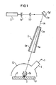
- FIG. 1 shows a highly simplified schematic illustration of a test arrangement for the contactless determination of defects D in non-structured areas F, in which a device E1 is used in the beam path Generation of a scanning light beam As, a widening optics Ao, a focusing optics Fo, a deflection device Ae and an aperture B are arranged in order to reduce the amount of scattered light.
- the scanning light beam As which is periodically moved back and forth in the plane of the drawing by the deflection device Ae in accordance with the double arrow Dpf, passes through a slit of a device E2 to be explained, onto the area F to be examined of a test specimen denoted by P.
- the test specimen P is moved in a direction perpendicular to the plane of the drawing, so that the surface F is scanned by the scanning light beam.
- the test specimen P can optionally also be moved with a meandering path. If the scanning light beam As occurs on defect-free areas of the area F, it leaves the device E2 again in the reflection direction through the slot through which it entered.
- the scanning light beam strikes a defect D, which can be a pore of the surface F, the inclusion of a foreign body, contamination of the surface or the like, the light is scattered and diffracted, the corresponding scattering lobe being denoted by Sk is.
- the light scattered and diffracted at the defect location is then at least partially collected by the device E2 on the light-sensitive surface of an optoelectronic receiver E, the output signal S of which indicates the defect D found.
- the device E1 for generating the scanning light beam As is in particular a laser, for example a HeCd laser, the beam of which in the Expanding optics Ao, for example, is expanded from an initial diameter of 1 mm to a diameter of 4 mm.
- the expanded laser beam is then focused onto the surface F by the focus optics Fo, the diameter of the beam at the point of impact being approximately 50 ⁇ m.
- the aperture B comprises two side walls labeled Sw and two end walls labeled Ew, the position and inclination of the two end walls Ew being matched to the maximum deflection of the scanning light beam As.
- the two side walls Sw are arranged shortly in front of or behind the deflection plane of the scanning light beam As lying in the plane of the drawing. Further details on the structure and the mode of operation of the diaphragm B will be explained later with reference to FIGS. 2 and 3 to 5.
- the device E2 for collecting the light deflected at the defect location is a hemisphere which is open at the bottom and which is arranged above the surface F of the test specimen P.
- the hemisphere is painted matt white on the inside, so that light scattered and diffracted from the defect D is often diffusely reflected and each surface element of the inner surface of the hemisphere is illuminated with approximately the same intensity.
- the light fluxes emanating from a defect D are detected and partially supplied to the light-sensitive surface of the optoelectronic receiver E, for example a photomultiplier, located in the region of the inner surface of the hemisphere.
- the device E2 which fulfill the desired collecting function are also possible. Deviating from the examination of the surface F shown in incident light, the examination can also be carried out in transmitted light, the Device E2 is then arranged in a corresponding manner on the underside of the test specimen P.
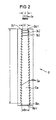
- FIG. 2 shows a side view of the panel B with the front end wall Ew removed.
- a sawtooth-shaped profile is also introduced on the inside, by which only additional diaphragm edges Bkz1 to Bkzn are indicated in FIG. 2.
- These additional diaphragm edges Bkz1 to Bkzn assigned to the reversal points of the scanning light beam As are offset in relation to the diaphragm edges Bk1 to Bkn in such a way that in the corner regions of the diaphragm B which is adjustably and adjustably screwed together from the two side walls Sw and the two end walls Ew, no mutual hindrance can occur.
- the two side walls Sw and the two end walls Ew are made of aluminum, the profiled inner surfaces each being anodized in matt black.
- the width b1 of the diaphragm gap formed by the first diaphragm edge Bk1 preferably corresponds to the diameter d of the scanning light beam As indicated by arrows and is 1 mm in the exemplary embodiment shown.
- the width bn of the aperture gap formed by the last aperture edge Bkn is 1.5 mm.
- Figure 3 shows the principle of operation of the aperture B, wherein only the first three diaphragm edges Bk1, Bk2 and Bk3 are indicated.
- the first diaphragm edge Bk1 forms a diaphragm gap of width b1, the light space of which is designated Lr1 and the shadow space of which is designated Sr1.
- the second diaphragm edge Bk2 forms a diaphragm gap of width b2, the light space of which is designated Lr2 and the shadow space of which is Sr2.
- the third diaphragm edge Bk3 forms a diaphragm gap of width b3, the light space of which is designated Lr3 and the shadow space of which is designated Sr3.
- the width b1 of the aperture gap formed by the first aperture edge Bk1 is dimensioned such that it is at least approximately equal to the diameter d of the scanning light beam As.
- the first diaphragm edge Bk1 then diffracts the light both into the shadow space Sr1 and into the light space Lr1.
- the second diaphragm edge Bk2 is now arranged in the shadow space Sr1 such that it cuts the first secondary maximum of the light diffracted by the first diaphragm edge Bk1 into the assigned shadow space Sr1.
- the second diaphragm edge Bk2 then bends the light back both into the assigned shadow space Sr2 and into the assigned light space Lr2.
- the third diaphragm edge Bk3 is then arranged in the shadow space Sr2 in such a way that it cuts the first secondary maximum of the light diffracted by the second diaphragm edge Bk2 into the assigned shadow space Sr2. It can be seen that the diffracted light is continuously reduced in the direction of the scanning light beam As and thus the halo of the scanning light beam As is reduced further and further.
- the intensity I of the scanning light beam As is entered over the beam cross section Sq before it enters the diaphragm B (see FIGS. 1 and 2).
- the resulting bell curve or Gaussian distribution curve is labeled Gk, while the unwanted stray light portion of the scanning light beam As is shown by curve branches St.
- the intensity I of the scanning light beam As after it emerges from the diaphragm B is plotted over the beam cross section Sq, the resulting curve being designated K.
- the typical bell curve Gk according to FIG. 4 is practically trimmed laterally due to the effect of the aperture B and the shading of the scattered light, and the resulting curve K approaches a rectangular shape R indicated by dash-dotted lines.
- the halo of the scanning light beam As is at least largely eliminated by the effect of the diaphragm B.
- the signal-to-noise ratio of the test arrangement shown in FIG. 1 is improved in such a way that even the smallest defects with dimensions in the submicron range can be reliably detected.
Landscapes
- Engineering & Computer Science (AREA)
- Textile Engineering (AREA)
- Physics & Mathematics (AREA)
- Health & Medical Sciences (AREA)
- Life Sciences & Earth Sciences (AREA)
- Chemical & Material Sciences (AREA)
- Analytical Chemistry (AREA)
- Biochemistry (AREA)
- General Health & Medical Sciences (AREA)
- General Physics & Mathematics (AREA)
- Immunology (AREA)
- Pathology (AREA)
- Investigating Materials By The Use Of Optical Means Adapted For Particular Applications (AREA)
Applications Claiming Priority (2)
| Application Number | Priority Date | Filing Date | Title |
|---|---|---|---|
| DE3532117 | 1985-09-09 | ||
| DE3532117 | 1985-09-09 |
Publications (2)
| Publication Number | Publication Date |
|---|---|
| EP0218865A1 true EP0218865A1 (fr) | 1987-04-22 |
| EP0218865B1 EP0218865B1 (fr) | 1989-12-27 |
Family
ID=6280467
Family Applications (1)
| Application Number | Title | Priority Date | Filing Date |
|---|---|---|---|
| EP86111838A Expired EP0218865B1 (fr) | 1985-09-09 | 1986-08-27 | Dispositif pour la détection sans contact de défauts dans des surfaces non structurées |
Country Status (3)
| Country | Link |
|---|---|
| US (1) | US4768878A (fr) |
| EP (1) | EP0218865B1 (fr) |
| DE (1) | DE3667855D1 (fr) |
Cited By (2)
| Publication number | Priority date | Publication date | Assignee | Title |
|---|---|---|---|---|
| EP0408337A1 (fr) * | 1989-07-13 | 1991-01-16 | De La Rue Systems Limited | Méthode et appareillage pour l'inspection d'une feuille |
| FR2681133A1 (fr) * | 1991-09-11 | 1993-03-12 | Languedoc Verrerie | Dispositif d'emission ou d'absorption de lumiere pour le controle sans contact d'objets. |
Families Citing this family (6)
| Publication number | Priority date | Publication date | Assignee | Title |
|---|---|---|---|---|
| JP3142852B2 (ja) * | 1990-02-20 | 2001-03-07 | 株式会社日立製作所 | 表面欠陥検査装置 |
| US5155777A (en) * | 1991-06-26 | 1992-10-13 | International Business Machines Corporation | Scattered light blocking layer for optoelectronic receivers |
| US5309339A (en) * | 1992-06-24 | 1994-05-03 | The Schepens Eye Research Institute, Inc. | Concentrator for laser light |
| JP2800587B2 (ja) * | 1992-10-05 | 1998-09-21 | 松下電器産業株式会社 | 異物検査装置および異物検査方法 |
| US5444265A (en) * | 1993-02-23 | 1995-08-22 | Lsi Logic Corporation | Method and apparatus for detecting defective semiconductor wafers during fabrication thereof |
| DE10319543B4 (de) * | 2003-04-30 | 2011-03-03 | Byk-Gardner Gmbh | Vorrichtung und Verfahren zur Bestimmung von Oberflächeneigenschaften |
Citations (4)
| Publication number | Priority date | Publication date | Assignee | Title |
|---|---|---|---|---|
| US3917414A (en) * | 1973-10-11 | 1975-11-04 | Geisco Associates | Optical inspection system |
| FR2477288A1 (fr) * | 1980-03-03 | 1981-09-04 | Vidal Bernard | Piege a lumiere a discrimination angulaire |
| US4378159A (en) * | 1981-03-30 | 1983-03-29 | Tencor Instruments | Scanning contaminant and defect detector |
| EP0146005B1 (fr) * | 1983-11-26 | 1991-08-28 | Kabushiki Kaisha Toshiba | Appareil pour la détection de défauts de surface |
Family Cites Families (5)
| Publication number | Priority date | Publication date | Assignee | Title |
|---|---|---|---|---|
| US2422273A (en) * | 1942-11-28 | 1947-06-17 | Brown Instr Co | Lens type radiation pyrometer |
| DE1473681A1 (de) * | 1965-11-17 | 1969-02-06 | Agfa Gevaert Ag | Verfahren zur optischen Fehlersuche,besonders an grossflaechigen Materialien |
| CH592933A5 (fr) * | 1976-04-05 | 1977-11-15 | Cerberus Ag | |
| JPS59208408A (ja) * | 1983-05-13 | 1984-11-26 | Toshiba Corp | 表面検査方法及びその装置 |
| US4601576A (en) * | 1983-12-09 | 1986-07-22 | Tencor Instruments | Light collector for optical contaminant and flaw detector |
-
1986
- 1986-08-27 DE DE8686111838T patent/DE3667855D1/de not_active Expired - Fee Related
- 1986-08-27 EP EP86111838A patent/EP0218865B1/fr not_active Expired
- 1986-09-09 US US06/905,186 patent/US4768878A/en not_active Expired - Fee Related
Patent Citations (4)
| Publication number | Priority date | Publication date | Assignee | Title |
|---|---|---|---|---|
| US3917414A (en) * | 1973-10-11 | 1975-11-04 | Geisco Associates | Optical inspection system |
| FR2477288A1 (fr) * | 1980-03-03 | 1981-09-04 | Vidal Bernard | Piege a lumiere a discrimination angulaire |
| US4378159A (en) * | 1981-03-30 | 1983-03-29 | Tencor Instruments | Scanning contaminant and defect detector |
| EP0146005B1 (fr) * | 1983-11-26 | 1991-08-28 | Kabushiki Kaisha Toshiba | Appareil pour la détection de défauts de surface |
Cited By (5)
| Publication number | Priority date | Publication date | Assignee | Title |
|---|---|---|---|---|
| EP0408337A1 (fr) * | 1989-07-13 | 1991-01-16 | De La Rue Systems Limited | Méthode et appareillage pour l'inspection d'une feuille |
| US5084628A (en) * | 1989-07-13 | 1992-01-28 | De La Rue Systems Ltd. | Sheet inspection method and apparatus having retroreflecting means |
| FR2681133A1 (fr) * | 1991-09-11 | 1993-03-12 | Languedoc Verrerie | Dispositif d'emission ou d'absorption de lumiere pour le controle sans contact d'objets. |
| EP0533534A1 (fr) * | 1991-09-11 | 1993-03-24 | Verrerie Du Languedoc Et Cie. | Dispositif d'émission ou d'absorption de lumière pour le contrôle sans contact d'objets |
| US5258611A (en) * | 1991-09-11 | 1993-11-02 | Verreries Du Languedoc | Light emission or absorption device for the contactless inspection of articles having a plurality of light sources and an elongate light guide |
Also Published As
| Publication number | Publication date |
|---|---|
| US4768878A (en) | 1988-09-06 |
| DE3667855D1 (de) | 1990-02-01 |
| EP0218865B1 (fr) | 1989-12-27 |
Similar Documents
| Publication | Publication Date | Title |
|---|---|---|
| DE19960653B4 (de) | Verfahren und Vorrichtung für die Detektion oder Lagebestimmung von Kanten | |
| DE2436110C3 (de) | Vorrichtung zur Feststellung von Herstellungsfehlern in einer bewegten Materialbahn | |
| EP2411787B1 (fr) | Dispositif pour déterminer la granulométrie de particules | |
| DE3913228C2 (de) | Spektroskopiesystem diffuser Reflexion und Verfahren zum Erhalten eines diffusen Reflexionsspektrums | |
| DE3926349C2 (fr) | ||
| DE3309584A1 (de) | Optisches inspektionssystem | |
| DE3034903A1 (de) | System zur erfassung von defekten | |
| DE2620091A1 (de) | Messystem zum bestimmen der kontur der oberflaeche eines gegenstands | |
| DE3303140A1 (de) | Infrarot-spektrometer | |
| DE2428123A1 (de) | Anordnung zum nachweisen von fehlstellen mittels abtastung durch einen laserstrahl | |
| DE4434699C2 (de) | Anordnung zur Prüfung durchsichtiger oder spiegelnder Objekte | |
| EP0218865B1 (fr) | Dispositif pour la détection sans contact de défauts dans des surfaces non structurées | |
| DE3409657A1 (de) | Dunkelfeldbeleuchtungseinrichtung fuer mikroskope | |
| DE2550814A1 (de) | Zeilentastvorrichtung fuer materialbahnen zur fehlstellenermittlung | |
| DE2306764A1 (de) | Mikroschwaerzungsmessverfahren und mikroschwaerzungsmesser bzw. mikrodensitometer | |
| WO2024068294A1 (fr) | Procédé de mesure pour réflectométrie euv, et réflectomètre euv | |
| DE2718711C2 (fr) | ||
| DE3533590A1 (de) | Abtasteinrichtung fuer halbton-durchsichtsvorlagen | |
| DE4426956C2 (de) | Verfahren zur Bestimmung der Geschwindigkeit einer Strömung | |
| DE10304105A1 (de) | Verfahren zur Bestimmung der Fokusabweichung einer optischen Anordnung | |
| DE2816986C3 (de) | Anordnung zum Aufsuchen von Fehlern auf laufenden Bändern | |
| DE3307591C2 (de) | Verfahren zur optischen Kontrolle der Oberfläche eines Prüfgutes | |
| DE2251915A1 (de) | Vorrichtung zum feststellen von flekken oder fehlern in einer oberflaeche | |
| CH669663A5 (fr) | ||
| DE4137673A1 (de) | Reflektometer |
Legal Events
| Date | Code | Title | Description |
|---|---|---|---|
| PUAI | Public reference made under article 153(3) epc to a published international application that has entered the european phase |
Free format text: ORIGINAL CODE: 0009012 |
|
| AK | Designated contracting states |
Kind code of ref document: A1 Designated state(s): CH DE FR GB LI |
|
| 17P | Request for examination filed |
Effective date: 19870522 |
|
| 17Q | First examination report despatched |
Effective date: 19890531 |
|
| GRAA | (expected) grant |
Free format text: ORIGINAL CODE: 0009210 |
|
| AK | Designated contracting states |
Kind code of ref document: B1 Designated state(s): CH DE FR GB LI |
|
| REF | Corresponds to: |
Ref document number: 3667855 Country of ref document: DE Date of ref document: 19900201 |
|
| ET | Fr: translation filed | ||
| GBT | Gb: translation of ep patent filed (gb section 77(6)(a)/1977) | ||
| PG25 | Lapsed in a contracting state [announced via postgrant information from national office to epo] |
Ref country code: GB Effective date: 19900827 |
|
| PG25 | Lapsed in a contracting state [announced via postgrant information from national office to epo] |
Ref country code: LI Effective date: 19900831 Ref country code: CH Effective date: 19900831 |
|
| PLBE | No opposition filed within time limit |
Free format text: ORIGINAL CODE: 0009261 |
|
| STAA | Information on the status of an ep patent application or granted ep patent |
Free format text: STATUS: NO OPPOSITION FILED WITHIN TIME LIMIT |
|
| 26N | No opposition filed | ||
| GBPC | Gb: european patent ceased through non-payment of renewal fee | ||
| PG25 | Lapsed in a contracting state [announced via postgrant information from national office to epo] |
Ref country code: FR Effective date: 19910430 |
|
| REG | Reference to a national code |
Ref country code: CH Ref legal event code: PL |
|
| PG25 | Lapsed in a contracting state [announced via postgrant information from national office to epo] |
Ref country code: DE Effective date: 19910501 |
|
| REG | Reference to a national code |
Ref country code: FR Ref legal event code: ST |