EP0218644B1 - Filter mit änderlichem volumen oder konzentrator - Google Patents
Filter mit änderlichem volumen oder konzentrator Download PDFInfo
- Publication number
- EP0218644B1 EP0218644B1 EP86902282A EP86902282A EP0218644B1 EP 0218644 B1 EP0218644 B1 EP 0218644B1 EP 86902282 A EP86902282 A EP 86902282A EP 86902282 A EP86902282 A EP 86902282A EP 0218644 B1 EP0218644 B1 EP 0218644B1
- Authority
- EP
- European Patent Office
- Prior art keywords
- shell
- liquid
- fibres
- solids
- gas
- Prior art date
- Legal status (The legal status is an assumption and is not a legal conclusion. Google has not performed a legal analysis and makes no representation as to the accuracy of the status listed.)
- Expired
Links
- 239000007788 liquid Substances 0.000 claims abstract description 63
- 239000007787 solid Substances 0.000 claims abstract description 49
- 239000000725 suspension Substances 0.000 claims abstract description 49
- 239000000835 fiber Substances 0.000 claims abstract description 45
- 239000011148 porous material Substances 0.000 claims abstract description 32
- 230000000717 retained effect Effects 0.000 claims abstract description 14
- 239000012530 fluid Substances 0.000 claims abstract description 7
- 238000000034 method Methods 0.000 claims description 16
- 230000002441 reversible effect Effects 0.000 claims description 15
- 238000007789 sealing Methods 0.000 claims description 11
- 239000006194 liquid suspension Substances 0.000 claims description 10
- 230000008859 change Effects 0.000 claims description 5
- 238000007599 discharging Methods 0.000 claims description 5
- 239000002245 particle Substances 0.000 claims description 4
- 238000006073 displacement reaction Methods 0.000 claims description 2
- 230000003111 delayed effect Effects 0.000 claims 2
- 238000010924 continuous production Methods 0.000 claims 1
- 230000014759 maintenance of location Effects 0.000 claims 1
- 230000003252 repetitive effect Effects 0.000 claims 1
- 239000007789 gas Substances 0.000 description 40
- 238000001816 cooling Methods 0.000 description 12
- 238000004140 cleaning Methods 0.000 description 9
- 239000012528 membrane Substances 0.000 description 7
- 238000001914 filtration Methods 0.000 description 5
- XLYOFNOQVPJJNP-UHFFFAOYSA-N water Substances O XLYOFNOQVPJJNP-UHFFFAOYSA-N 0.000 description 5
- 238000011001 backwashing Methods 0.000 description 4
- 239000012141 concentrate Substances 0.000 description 4
- 238000002474 experimental method Methods 0.000 description 4
- 239000004743 Polypropylene Substances 0.000 description 3
- 238000013459 approach Methods 0.000 description 3
- 230000007423 decrease Effects 0.000 description 3
- 238000001704 evaporation Methods 0.000 description 3
- 230000008020 evaporation Effects 0.000 description 3
- -1 polypropylene Polymers 0.000 description 3
- 229920001155 polypropylene Polymers 0.000 description 3
- 238000005406 washing Methods 0.000 description 3
- VEXZGXHMUGYJMC-UHFFFAOYSA-N Hydrochloric acid Chemical compound Cl VEXZGXHMUGYJMC-UHFFFAOYSA-N 0.000 description 2
- 239000004372 Polyvinyl alcohol Substances 0.000 description 2
- 230000008602 contraction Effects 0.000 description 2
- 230000007547 defect Effects 0.000 description 2
- 238000010586 diagram Methods 0.000 description 2
- 230000000694 effects Effects 0.000 description 2
- 239000012065 filter cake Substances 0.000 description 2
- 239000000706 filtrate Substances 0.000 description 2
- 238000004519 manufacturing process Methods 0.000 description 2
- 239000012466 permeate Substances 0.000 description 2
- 229920002451 polyvinyl alcohol Polymers 0.000 description 2
- 238000012545 processing Methods 0.000 description 2
- 239000000047 product Substances 0.000 description 2
- 238000011084 recovery Methods 0.000 description 2
- 238000001223 reverse osmosis Methods 0.000 description 2
- 229920006395 saturated elastomer Polymers 0.000 description 2
- 230000005653 Brownian motion process Effects 0.000 description 1
- VTYYLEPIZMXCLO-UHFFFAOYSA-L Calcium carbonate Chemical compound [Ca+2].[O-]C([O-])=O VTYYLEPIZMXCLO-UHFFFAOYSA-L 0.000 description 1
- 239000004677 Nylon Substances 0.000 description 1
- CZMRCDWAGMRECN-UGDNZRGBSA-N Sucrose Chemical compound O[C@H]1[C@H](O)[C@@H](CO)O[C@@]1(CO)O[C@@H]1[C@H](O)[C@@H](O)[C@H](O)[C@@H](CO)O1 CZMRCDWAGMRECN-UGDNZRGBSA-N 0.000 description 1
- 229930006000 Sucrose Natural products 0.000 description 1
- WNROFYMDJYEPJX-UHFFFAOYSA-K aluminium hydroxide Chemical compound [OH-].[OH-].[OH-].[Al+3] WNROFYMDJYEPJX-UHFFFAOYSA-K 0.000 description 1
- 229910021502 aluminium hydroxide Inorganic materials 0.000 description 1
- 230000008901 benefit Effects 0.000 description 1
- 230000000903 blocking effect Effects 0.000 description 1
- 238000005537 brownian motion Methods 0.000 description 1
- 238000004891 communication Methods 0.000 description 1
- 230000000295 complement effect Effects 0.000 description 1
- 238000010276 construction Methods 0.000 description 1
- 239000000112 cooling gas Substances 0.000 description 1
- 239000000498 cooling water Substances 0.000 description 1
- 238000009295 crossflow filtration Methods 0.000 description 1
- 230000002939 deleterious effect Effects 0.000 description 1
- 238000011026 diafiltration Methods 0.000 description 1
- 238000009792 diffusion process Methods 0.000 description 1
- 230000008030 elimination Effects 0.000 description 1
- 238000003379 elimination reaction Methods 0.000 description 1
- 239000000839 emulsion Substances 0.000 description 1
- 239000002657 fibrous material Substances 0.000 description 1
- 239000008394 flocculating agent Substances 0.000 description 1
- 230000004907 flux Effects 0.000 description 1
- 235000011389 fruit/vegetable juice Nutrition 0.000 description 1
- 239000011256 inorganic filler Substances 0.000 description 1
- 229910003475 inorganic filler Inorganic materials 0.000 description 1
- 210000003141 lower extremity Anatomy 0.000 description 1
- 239000000463 material Substances 0.000 description 1
- 238000005065 mining Methods 0.000 description 1
- 238000012986 modification Methods 0.000 description 1
- 230000004048 modification Effects 0.000 description 1
- 229920001778 nylon Polymers 0.000 description 1
- 230000003287 optical effect Effects 0.000 description 1
- 230000000737 periodic effect Effects 0.000 description 1
- 238000011045 prefiltration Methods 0.000 description 1
- 238000003825 pressing Methods 0.000 description 1
- 230000009467 reduction Effects 0.000 description 1
- 238000012552 review Methods 0.000 description 1
- 239000000126 substance Substances 0.000 description 1
- 229960004793 sucrose Drugs 0.000 description 1
- 238000012360 testing method Methods 0.000 description 1
- 210000001364 upper extremity Anatomy 0.000 description 1
- 238000009736 wetting Methods 0.000 description 1
Images
Classifications
-
- B—PERFORMING OPERATIONS; TRANSPORTING
- B01—PHYSICAL OR CHEMICAL PROCESSES OR APPARATUS IN GENERAL
- B01D—SEPARATION
- B01D63/00—Apparatus in general for separation processes using semi-permeable membranes
- B01D63/02—Hollow fibre modules
-
- B—PERFORMING OPERATIONS; TRANSPORTING
- B01—PHYSICAL OR CHEMICAL PROCESSES OR APPARATUS IN GENERAL
- B01D—SEPARATION
- B01D65/00—Accessories or auxiliary operations, in general, for separation processes or apparatus using semi-permeable membranes
- B01D65/02—Membrane cleaning or sterilisation ; Membrane regeneration
-
- B—PERFORMING OPERATIONS; TRANSPORTING
- B01—PHYSICAL OR CHEMICAL PROCESSES OR APPARATUS IN GENERAL
- B01D—SEPARATION
- B01D2201/00—Details relating to filtering apparatus
- B01D2201/18—Filters characterised by the openings or pores
- B01D2201/184—Special form, dimension of the openings, pores of the filtering elements
- B01D2201/186—Pore openings which can be modified
-
- B—PERFORMING OPERATIONS; TRANSPORTING
- B01—PHYSICAL OR CHEMICAL PROCESSES OR APPARATUS IN GENERAL
- B01D—SEPARATION
- B01D2313/00—Details relating to membrane modules or apparatus
- B01D2313/02—Specific tightening or locking mechanisms
-
- B—PERFORMING OPERATIONS; TRANSPORTING
- B01—PHYSICAL OR CHEMICAL PROCESSES OR APPARATUS IN GENERAL
- B01D—SEPARATION
- B01D2313/00—Details relating to membrane modules or apparatus
- B01D2313/48—Mechanisms for switching between regular separation operations and washing
-
- B—PERFORMING OPERATIONS; TRANSPORTING
- B01—PHYSICAL OR CHEMICAL PROCESSES OR APPARATUS IN GENERAL
- B01D—SEPARATION
- B01D2321/00—Details relating to membrane cleaning, regeneration, sterilization or to the prevention of fouling
- B01D2321/18—Use of gases
Definitions
- This invention relates to a variable volume filter or concentrator containing a bundle of porous hollow fibres.
- the producers of clear liquids usually regard all visible traces of solids as wastes.
- the methods used often involve the addition of flocculants and filter aids which contaminate the solids.
- the solids content tends to be low, encouraging the use of methods which remove clear liquid from a continuously fed feed suspension tank in which the solids content increases until some deleterious effect arises, necessitating the dumping of the contents of the feed suspension tank into some other device.
- the accumulating solids have been steadily slowing production and productivity could benefit from some device which continuously rejected concentrated solids.
- Transmembrane gas backwashing is impossible in very finely pored filters such as reverse osmosis membranes and ultrafilters because the pressures needed to overcome surface tension are far beyond the strengths of normal hollow fibre membranes used for these purposes; wetting liquids may pass but not gases. Any gas bubbles passing through such a membrane indicate the presence of pin hole defects in the membrane. Hence, this invention has no application to reverse osmosis or to true ultrafilters.
- This invention is concerned with microfilters which contain larger pores than those of ultrafilters and which range from 0.01 to 10 microns. Usually, the larger of the pores are so distributed that clarified liquids are free of all visible turbidity. Turbidity of the clarified liquid involves more than pore and particle size, obeying and arising from well known optical laws.
- the above inventions can be improved by attention to the volume of the shell which encloses the porous hollow fibre filter bundle.
- the shell should not be of unvarying diameter. As filtration progresses in a common recycle concentration mode wherein clarified liquid and concentrated solids are both rejected as rapidly as possible, the solids content of the feed suspension rises steeply. It is then desired to expand the shell to maintain a constant pressure drop along the length of the fibres. The start of each new batch needs a contraction in the shell diameter. On the other hand, at each combined permeate/gas ejection of solids, it is desired to expand the shell to facilitate discharge and inter- fibre cleaning.
- the prior art does not recognise the value of an elastic sleeve whose elasticity is adjusted or is made adjustable by a back-pressure or tensioning so that a pulsed feed supply can cause controlled rubbing between the fibres and between the fibres and elastic sleeve without fibre tangling.
- Such controlled rubbing gives extra control of the thickness of any filter cake thus allowing reduction of high feed recycle formerly used as a sole means of control.
- French patent No. 2,267,183 does not address the vital need in cross-flow filtration for a shell which varies in diameter during a run and must often expand every minute to allow solids discharge.
- apparatus for treating a liquid suspension comprising a shell, a plurality of elastic, hollow, microporous fibres within the shell, means for supplying pressurised feed suspension to the shell, means for withdrawing clarified liquid from the shell, means for applying a pressurised reverse flow or backwash of clarified liquid followed by a pressurised reverse flow or backwash of gas to discharge solids retained on or in the fibres or otherwise within the shell, means for discharging concentrated suspension, and a variable volume elongated diaphragm within the shell.
- the pressurised gas is so applied as to backwash the full length of the fibres by displacing any lumen liquid with gas at a pressure below the bubble point of the walls of the fibres.
- the shell is then sealed with the relatively incompressible feed liquid so that gas cannot flow through the fibre walls as the pressure of the trapped gas is raised beyond the bubble point.
- the liquid seal is then released to allow the trapped gas to escape substantially uniformly through the fibre walls even at the most distant point from the lumen inlet thus minimizing subsequent preferential washing of pores near the gas inlet.
- the concentrator includes means for sealing the relatively incompressible feed suspension in the shell upon displacement of liquid from the fibre lumens by the pressurised gas so that the gas may be trapped in the lumens at a pressure above the bubble point of the fibre walls and means to allow the sudden release of the gas substantially uniformly through the fibre walls.
- the diameter of the diaphragm is adapted to change according to a preset schedule or is adapted to change to maintain a controllable pressure drop along the shell.
- the pressure drop is substantially independent of feed viscosity.
- the diameter may also increase to facilitate periodic discharge of accumulated solids on or between the hollow fibres.
- the invention also provides a method of:
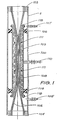
- the hollow fibre concentrator shown in Fig. 1 includes a shell 100 within which is positioned a bundle of hollow, porous, polymeric fibres 102.
- each fibre is made of polypropylene, has an average pore size of 0.2 micron, a wall thickness of 200 micron and a lumen diameter of 200 micron.
- There are 3000 hollow fibres in the bundle 102 but this number as well as individual fibre dimensions may be varied according to operational requirements.
- Sealing plugs 103 and 104 hold the ends of the fibres 102 in place without blocking their lumens and close off each end of the shell 100.
- Liquid feed suspension to be concentrated is pumped into the shell 100 through feed suspension inlet 105 and passes over the external walls of the fibres 102. Some of the feed suspension passes through the walls of the fibres into the lumens of the fibres to be drawn off as clarified liquid through the shell outlets formed in the sealing plugs 103 and 104.
- the remaining feed suspension and some of the rejected solids flow between the fibres 102 and leave the shell 100 through outlet 107.
- the remainder of the rejected solids is held onto or within the fibres or is otherwise retained within the shell.
- the bundle of fibres 102 is positioned within a deformable tubular diaphragm 108 the ends 118 of which are secured over and to the upper and lower extremities of a diaphragm holder tube 109 held in position by sealing plugs 106.
- feed suspension enters the shell 100 through inlet 105 at pressure P1 and impinges upon the rigid diaphragm holder tube 109 before entering the fibre bundle.
- the fibre bundle is confined by the deformable diaphragm sleeve 108 and the position of the diaphragm 108 is set by fluid entering the diaphragm control pressure inlet 110 at a pressure P3. Raising the pressure P3 forces the diaphragm 108 tightly onto the hollow fibre bundle whilst reducing the pressure enough ultimately allows the diaphragm 108 to lie fully against the diaphragm holder tube 109.
- the thickness or elasticity or internal ducting of the diaphragm 108 can be selected to give any desired pressure drop configuration along the length of the fibres.
- Elastic bands 111 which are a simple choice to achieve this are indicated in Fig. 1 but they are by no means necessary.
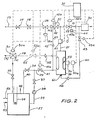
- variable volume tubular diaphragm of the invention can be applied to a cross-flow hollow fibre concentrator system of the kind shown in Fig. 2 which operates in a number of modes.
- the system of Fig. 2 will be first described without reference to the diaphragm.
- the pump 38 draws feed suspension from the feed suspension tank 27 through pump suction line 39 thence through inlet pressure valve 37 and delivers it through feed suspension inlet line 29 (having a feed suspension stop solenoid valve 41) to the cross-flow concentrator 20.
- Feed suspension passes over the surface of the hollow fibres inside the cross-flow concentrator 20 and some of the fluid passes through the fibres into the lumens to be delivered to the clarified liquid outlet line 21.
- the clarified liquid in line 21 passes through clarified liquid hold-up cylinder 47 which is operated by solenoid 47a, clarified liquid control valve 22 controlled by solenoid 22a and flow sensor 32 to a clarified liquid collection point. Flow of clarified liquid to line 23 is prevented by check valve 51.
- Concentrated feed suspension from the cross-flow concentrator 20 passes through the check valve 35 and the solenoid-operated shell sealing valve 55 (when fitted) into line 28 from which it is delivered to the three way concentrate divert valve 30 controlled by solenoid 30a.
- the valve 30 has outlet paths (a) and (b) which lead to the feed suspension tank 27 and to a concentrate collection point respectively. In the concentration mode, the valve 30 is in position (a) so that the concentrated feed suspension passes through back pressure valve 33 into the tank 27.
- a bypass valve 34 in bypass line 40 is set to control, together with the inlet pressure valve 37, the flow rate through the cross-flow concentrator 20.
- the feed suspension tank 27 has a feed suspension inlet 53 and a washing inlet 52, heater 54 and vent 48.
- the suspension inlet pressure, the concentrated suspension outlet pressure and the clarified liquid pressure are controlled or set by the said valves 37, 33 and 22 respectively.
- the liquor issuing from valve 22 is monitored by flow sensor 32 and the parameters sensed are used as inputs to the programmable controller 31.
- the controller 31 compares the actual flow rate of the clarified liquid with preset values of flow rate and time to initiate a discharge cycle.
- the first criterion is the clarified liquid discharge flow rate and once it decreases to a predetermined and set rate the controller 31 initiates a discharge cycle.
- the second criterion is time where the controller initiates a discharge cycle at fixed time intervals. The second criterion is more appropriate for feed suspensions where the liquor flow rate does not decline very rapidly.
- Substantially dry gas is introduced to the system during the discharge mode through line 23 which includes a gas pressure control valve 24, a gas flow valve 25 and a gas stop valve 26 controlled by solenoid 26a.
- the gas In order to allow evaporation (and hence cooling), the gas must be under saturated with respect to the liquid vapour at the operating temperature.
- a lumenal cooling discharge line 60 connected between the lumenal air outlet 61 and clarified liquid outlet line 62 contains a lumenal cooling stop valve 43 which is controlled by solenoid 43a and a lumenal cooling check valve 46.
- a shell cooling line 63 connected between the feed inlet line 29 and the shell cooling divert valve 42 in line 23 has a shell cooling check valve 45.
- the shell cooling divert valve 42 is controlled by solenoid 42a and has inlet paths (a) and (b) the functions of which will be described below.
- the programmable controller 31 sets the system to discharge mode by actuating solenoids 22a, 26a, 43a and 30a which in turn close valve 22, open valve 26, close valve 43 and change the outlet path of the three way concentrate divert valve 30 to path (b) so that the subsequent variable volume clarified liquid hold up and the gaseous discharge medium as well as the material dislodged from the fibres can be discharged from the system.
- the programmable controller initiates a lumenal flow through of gas for rapid evaporative cooling of the hollow fibres prior to reverse flow cleaning by actuating solenoids 22a, 43a, 41a and 26a so that valve 22 is closed, valve 43 is open, valve 41 is closed and valve 26 is open for a predetermined time, termed the lumenal cool time.
- the lumenal cooling gas flows through line 21 without disturbing the clarified liquid in the hold-up cylinder 47 and is discharged into the clarified liquid line through valve 43.
- the lumenal cool time is sufficient to reduce the temperature of the fibres to within safe limits.
- the solids discharge is then initiated by the programmable controller 31 which actuates solenoid 26a to open gas valve 26 and the solenoid 47a of clarified liquid hold up cylinder 47 so that the liquid content of that device is discharged under pressure from gas supplied through valve 26 into the lumens and across the fibres in the reverse direction to normal operation so as to expand all the pores and to displace all the liquid in any solids lodged within the pores of the fibres.
- valve 26 is closed by solenoid 26a at the end of the gas discharge time.
- programmable controller 31 At the end of the discharge cycle time, programmable controller 31 returns the system to the concentration mode as described above, except that valve 22 is kept closed until the hold-up cylinder 47 is filled with clarified liquid.
- the programmable controller initiates a shell-side cooling cycle by actuating valve 41 (closed), 26 (open), and 42 (to position a) for a preset time, termed the shell-side cool time, which is sufficient to reduce the temperature of the fibres to an optimal safe level.
- the programmable controller initiates a reverse flow cleaning cycle by actuating valves 22 (closed), 42 (to position b) for the reverse flow cycle time.
- the programmable controller returns the system to the concentration mode as described above.
- the system so far described is improved by the provision of the diaphragm shown in Fig. 1.
- the deformable variable diameter diaphragm 49 shown schematically in Fig. 2 is controlled in position by the solenoid valve 50.
- Solenoid valve 50 is controlled by the programmable controller 31 to give any desired sequence of diaphragm positions.
- the diaphragm is expanded whenever the solids ejection cycle begins and is not contracted until feed suspension flow is recommenced.
- the control of the contraction during the filtration phase may be by a schedule determined by experiment on the feed. Or simply, the position may be controlled in most circumstances by the pressure drop between the suspension inlet line 29 and the suspension outlet line 28.
- a very flexible diaphragm adjusts along its length for volume and viscosity changes occurring along the length of the shell.
- a filter was constructed as shown in Fig. 1. It was 50 cm long and contained 500 polypropylene hollow fibres of 200 micron bore and 200 micron walls. The original average pore diameter was 0.2 micron but the pore walls were coated with a hydrophilic nylon according to our co-pending Australian patent application PG 1368 (European Patent Application No. 84903426.9) TREATMENT OF POROUS MEMBRANES.
- variable diameter diaphragm With the variable diameter diaphragm wide open there was a clear path around the fibre bundle of 1 cm all round.
- the rate of permeation dropped in 3 minutes from 20 Usq.m./hour to below 1 Usq.m./hr.
- Fig. 1 The apparatus of Fig. 1 was modified by replacing the variable diameter diaphragm with a rigid sleeve.
- the permeation rate of whole egg was again 20 Usq.m./hr. However when attempts were made to blow back by reverse direction of gas through the pores no cleaning occurred.
- Example 2 without the valve 55 was used to separate clear water from an emulsion of 0.1% BP FEDARO-M emulsifiable oil in water. After standing 8 hours it was found that the oil had swollen the polypropylene fibres 10% in all dimensions. Loops of fibre were forced along with the feed and hung out of the exit end of the confining rigid sleeve. They could not be forced back by reversing the flow.
- a crude cane sugar juice was put through the apparatus of Fig. 2 without valve 55 and without the flexible diaphragm and it quickly blocked with fine fibrous material which could not be dislodged by the air backwash through the larger pores.
- variable diaphragm when used, it was found that small paper-like aggregates of the fibre could be blown out when the diaphragm was wide open. This is commercially very useful since it eliminates the need for fine 5-10 micron pre-filters.
- Example 4 was repeated but the feed was a mixed suspension of precipitated chalk and aluminium hydroxide. Lumps of chalk accumulated in the fibre bundle and could only be removed by opening the diaphragm fully.
- the elasticity of the elastic sleeve may be adjusted by a back-pressure or tensioning so that a pulsed feed supply can cause controlled rubbing between the fibres and between the fibres and the elastic sleeve to assist greatly the removal of filter cake. Pulsing may be achieved by altering the flow rate of the feed suspension as it enters the shell, by varying the pressure at diaphragm control inlet 110 or by piercing the sleeve at or near its top to give controlled communication between diaphragm control inlet 110 and outlet 107 and then applying the pressure at inlet 105.
Landscapes
- Chemical & Material Sciences (AREA)
- Chemical Kinetics & Catalysis (AREA)
- Separation Using Semi-Permeable Membranes (AREA)
- Tea And Coffee (AREA)
- Treatment Of Liquids With Adsorbents In General (AREA)
- Fats And Perfumes (AREA)
Claims (15)
Priority Applications (1)
| Application Number | Priority Date | Filing Date | Title |
|---|---|---|---|
| AT86902282T ATE53510T1 (de) | 1985-04-10 | 1986-04-04 | Filter mit aenderlichem volumen oder konzentrator. |
Applications Claiming Priority (4)
| Application Number | Priority Date | Filing Date | Title |
|---|---|---|---|
| AU81/85 | 1985-04-10 | ||
| AUPH008185 | 1985-04-10 | ||
| AU3356/85 | 1985-11-11 | ||
| AUPH335685 | 1985-11-11 |
Publications (3)
| Publication Number | Publication Date |
|---|---|
| EP0218644A1 EP0218644A1 (de) | 1987-04-22 |
| EP0218644A4 EP0218644A4 (de) | 1987-08-10 |
| EP0218644B1 true EP0218644B1 (de) | 1990-06-13 |
Family
ID=25642928
Family Applications (1)
| Application Number | Title | Priority Date | Filing Date |
|---|---|---|---|
| EP86902282A Expired EP0218644B1 (de) | 1985-04-10 | 1986-04-04 | Filter mit änderlichem volumen oder konzentrator |
Country Status (8)
| Country | Link |
|---|---|
| US (1) | US4793932A (de) |
| EP (1) | EP0218644B1 (de) |
| JP (1) | JPS62502452A (de) |
| AT (1) | ATE53510T1 (de) |
| CA (1) | CA1282345C (de) |
| DE (1) | DE3671843D1 (de) |
| MX (1) | MX161797A (de) |
| WO (1) | WO1986005997A1 (de) |
Families Citing this family (83)
| Publication number | Priority date | Publication date | Assignee | Title |
|---|---|---|---|---|
| EP0341573A3 (de) * | 1988-05-13 | 1990-05-09 | Sartorius Ag | Verfahren und Vorrichtung zur Filtration von Flüssigkeiten im Cross-Flow-Betrieb |
| US5639373A (en) | 1995-08-11 | 1997-06-17 | Zenon Environmental Inc. | Vertical skein of hollow fiber membranes and method of maintaining clean fiber surfaces while filtering a substrate to withdraw a permeate |
| ES2145010T3 (es) * | 1991-08-07 | 2000-07-01 | Usf Filtration Limited | Concentracion de solidos en una suspension utilizando membranas de fibra huecas. |
| US5358635A (en) * | 1993-04-16 | 1994-10-25 | Ecowater Systems, Inc. | Integrated reverse osmosis water treatment and storage system |
| US5972196A (en) * | 1995-06-07 | 1999-10-26 | Lynntech, Inc. | Electrochemical production of ozone and hydrogen peroxide |
| AU7354494A (en) * | 1994-05-25 | 1995-12-18 | Memtec America Corporation | Gas backwash of pleated filters |
| US20040238432A1 (en) | 1995-08-11 | 2004-12-02 | Mailvaganam Mahendran | Membrane filtration module with adjustable header spacing |
| US6077435A (en) * | 1996-03-15 | 2000-06-20 | Usf Filtration And Separations Group Inc. | Filtration monitoring and control system |
| CA2639642C (en) | 1996-12-20 | 2013-01-15 | Siemens Water Technologies Corp. | Scouring method |
| US6641733B2 (en) | 1998-09-25 | 2003-11-04 | U. S. Filter Wastewater Group, Inc. | Apparatus and method for cleaning membrane filtration modules |
| AUPP985099A0 (en) | 1999-04-20 | 1999-05-13 | Usf Filtration And Separations Group Inc. | Membrane filtration manifold system |
| WO2001010540A2 (en) * | 1999-08-05 | 2001-02-15 | Microfiltration Technology Aps | A method of cross-flow filtration and a cross-flow filtration installation |
| AUPQ680100A0 (en) | 2000-04-10 | 2000-05-11 | Usf Filtration And Separations Group Inc. | Hollow fibre restraining system |
| EP1322398B2 (de) * | 2000-09-19 | 2010-07-28 | Shell Technology Ventures Fund 1 B.V. | Filtervorrichtung und filtrationsmethode |
| AUPR064800A0 (en) | 2000-10-09 | 2000-11-02 | Usf Filtration And Separations Group Inc. | Improved membrane filtration system |
| AUPR143400A0 (en) | 2000-11-13 | 2000-12-07 | Usf Filtration And Separations Group Inc. | Modified membranes |
| AUPR421501A0 (en) | 2001-04-04 | 2001-05-03 | U.S. Filter Wastewater Group, Inc. | Potting method |
| AUPR584301A0 (en) | 2001-06-20 | 2001-07-12 | U.S. Filter Wastewater Group, Inc. | Membrane polymer compositions |
| AUPR692401A0 (en) | 2001-08-09 | 2001-08-30 | U.S. Filter Wastewater Group, Inc. | Method of cleaning membrane modules |
| US6706180B2 (en) * | 2001-08-13 | 2004-03-16 | Phase Inc. | System for vibration in a centrifuge |
| WO2003024582A1 (en) * | 2001-09-17 | 2003-03-27 | Fibra Limited | A device and a method for contacting a liquid with a gas |
| AUPR774201A0 (en) | 2001-09-18 | 2001-10-11 | U.S. Filter Wastewater Group, Inc. | High solids module |
| DE60213184T2 (de) | 2001-11-16 | 2007-06-28 | U.S. Filter Wastewater Group, Inc. | Methode zur Reinigung von Membranen |
| US7247238B2 (en) | 2002-02-12 | 2007-07-24 | Siemens Water Technologies Corp. | Poly(ethylene chlorotrifluoroethylene) membranes |
| AUPS300602A0 (en) | 2002-06-18 | 2002-07-11 | U.S. Filter Wastewater Group, Inc. | Methods of minimising the effect of integrity loss in hollow fibre membrane modules |
| KR101002466B1 (ko) | 2002-10-10 | 2010-12-17 | 지멘스 워터 테크놀로지스 코포레이션 | 역세척 방법 |
| AU2002953111A0 (en) | 2002-12-05 | 2002-12-19 | U. S. Filter Wastewater Group, Inc. | Mixing chamber |
| WO2004080601A2 (en) | 2003-03-11 | 2004-09-23 | Phase Inc. | Centrifuge with controlled discharge of dense material |
| US6971525B2 (en) | 2003-06-25 | 2005-12-06 | Phase Inc. | Centrifuge with combinations of multiple features |
| AU2003903507A0 (en) | 2003-07-08 | 2003-07-24 | U. S. Filter Wastewater Group, Inc. | Membrane post-treatment |
| US7371322B2 (en) | 2003-07-30 | 2008-05-13 | Phase Inc. | Filtration system and dynamic fluid separation method |
| EP1663461A4 (de) * | 2003-07-30 | 2009-01-14 | Phase Inc | Filtrationssystem mit verbesserter reinigung und dyamischer fluidtrennung |
| NZ545206A (en) | 2003-08-29 | 2009-03-31 | Siemens Water Tech Corp | Backwash |
| US7282147B2 (en) | 2003-10-07 | 2007-10-16 | Phase Inc. | Cleaning hollow core membrane fibers using vibration |
| CN100421772C (zh) | 2003-11-14 | 2008-10-01 | 西门子水技术公司 | 改进的组件清洗方法 |
| KR100453329B1 (ko) * | 2004-03-08 | 2004-10-21 | 주식회사 나노엔텍 | 밀도 조절형 섬유사 정밀여과장치 |
| US8758621B2 (en) | 2004-03-26 | 2014-06-24 | Evoqua Water Technologies Llc | Process and apparatus for purifying impure water using microfiltration or ultrafiltration in combination with reverse osmosis |
| CA2564007C (en) | 2004-04-22 | 2011-05-31 | Siemens Water Technologies Corp. | Filtration apparatus comprising a membrane bioreactor and a treatment vessel for digesting organic materials |
| GB0411290D0 (en) * | 2004-05-20 | 2004-06-23 | Water And Waste Uk Ltd | Fluid filter |
| WO2005113110A1 (en) * | 2004-05-20 | 2005-12-01 | Water Maiden Limited | Fluid filter |
| WO2006002469A1 (en) | 2004-07-02 | 2006-01-12 | U.S. Filter Wastewater Group, Inc | Gas transfer membrane |
| US8524794B2 (en) | 2004-07-05 | 2013-09-03 | Siemens Industry, Inc. | Hydrophilic membranes |
| NZ553178A (en) | 2004-08-20 | 2010-12-24 | Siemens Water Tech Corp | Square MBR manifolding system |
| WO2006026814A1 (en) | 2004-09-07 | 2006-03-16 | Siemens Water Technologies Corp. | Reduction of backwash liquid waste |
| EP1799334B1 (de) | 2004-09-14 | 2013-12-11 | Siemens Water Technologies LLC | Verfahren und vorrichtungen zum entfernen von feststoffen aus einem membranmodul |
| CN100548452C (zh) | 2004-09-15 | 2009-10-14 | 西门子水技术公司 | 一种薄膜过滤系统以及控制薄膜过滤系统中积垢的方法 |
| US7591950B2 (en) | 2004-11-02 | 2009-09-22 | Siemens Water Technologies Corp. | Submerged cross-flow filtration |
| EP1827664B1 (de) | 2004-12-03 | 2011-06-08 | Siemens Industry, Inc. | Membrannachbehandlung |
| EP1835985B1 (de) | 2004-12-24 | 2012-03-14 | Siemens Industry, Inc. | Reinigung in membranfiltrationssystemen |
| CA2591580A1 (en) | 2004-12-24 | 2006-06-29 | Siemens Water Technologies Corp. | Simple gas scouring method and apparatus |
| CA2605757A1 (en) | 2005-04-29 | 2006-11-09 | Siemens Water Technologies Corp. | Chemical clean for membrane filter |
| EP1901835B1 (de) | 2005-07-14 | 2012-11-14 | Siemens Industry, Inc. | Monopersulfatbehandlung von membranen |
| NZ565795A (en) | 2005-08-22 | 2011-03-31 | Siemens Water Tech Corp | An assembly for water filtration using a tube manifold to minimise backwash |
| WO2007044345A2 (en) | 2005-10-05 | 2007-04-19 | Siemens Water Technologies Corp. | Method and apparatus for treating wastewater |
| WO2007044415A2 (en) | 2005-10-05 | 2007-04-19 | Siemens Water Technologies Corp. | Method and apparatus for treating wastewater |
| US7455765B2 (en) | 2006-01-25 | 2008-11-25 | Siemens Water Technologies Corp. | Wastewater treatment system and method |
| WO2008006173A1 (en) * | 2006-07-14 | 2008-01-17 | Siemens Water Technologies Corp. | Improved monopersulfate treatment of membranes |
| US8293098B2 (en) | 2006-10-24 | 2012-10-23 | Siemens Industry, Inc. | Infiltration/inflow control for membrane bioreactor |
| US8318028B2 (en) | 2007-04-02 | 2012-11-27 | Siemens Industry, Inc. | Infiltration/inflow control for membrane bioreactor |
| US9764288B2 (en) | 2007-04-04 | 2017-09-19 | Evoqua Water Technologies Llc | Membrane module protection |
| JP4833353B2 (ja) | 2007-05-29 | 2011-12-07 | シーメンス ウォーター テクノロジース コーポレイション | パルス化エアリフトポンプを備えた膜モジュール |
| WO2009052197A2 (en) * | 2007-10-15 | 2009-04-23 | Stone Industry Recycling, Inc. D/B/A Water Treatment Technologies | Concentrator system and method of water filtration and recycling to drive industrial fabrication process |
| JP2013500144A (ja) | 2008-07-24 | 2013-01-07 | シーメンス インダストリー インコーポレイテッド | 濾過システムにおける濾過膜モジュールアレイに対して構造的支持を施すための方法および濾過システム |
| CA2734796A1 (en) | 2008-08-20 | 2010-02-25 | Siemens Water Technologies Corp. | Improved membrane system backwash energy efficiency |
| WO2010023656A1 (en) * | 2008-08-29 | 2010-03-04 | Nir Oz | Filter with adjustable porosity |
| AU2010101488B4 (en) | 2009-06-11 | 2013-05-02 | Evoqua Water Technologies Llc | Methods for cleaning a porous polymeric membrane and a kit for cleaning a porous polymeric membrane |
| US20110147308A1 (en) * | 2009-12-21 | 2011-06-23 | Siemens Water Technologies Corp. | Charged Porous Polymeric Membranes and Their Preparation |
| CN102869432B (zh) | 2010-04-30 | 2016-02-03 | 伊沃夸水处理技术有限责任公司 | 流体流分配装置 |
| AU2011305377B2 (en) | 2010-09-24 | 2014-11-20 | Evoqua Water Technologies Llc | Fluid control manifold for membrane filtration system |
| EP2529826A1 (de) * | 2011-05-31 | 2012-12-05 | Nederlandse Organisatie voor toegepast -natuurwetenschappelijk onderzoek TNO | Filtersystem mit deformierbarer Seitenwand |
| US9409110B2 (en) | 2011-07-14 | 2016-08-09 | Nalco Company | Method of maintaining water quality in a process stream |
| AU2012308799B2 (en) * | 2011-09-12 | 2017-07-06 | Solventum Intellectual Properties Company | Improved contactors, cartridges, components, systems, and related methods |
| JP2014528354A (ja) | 2011-09-30 | 2014-10-27 | エヴォクア ウォーター テクノロジーズ エルエルシーEvoqua Water Technologiesllc | 隔離バルブ |
| US9604166B2 (en) | 2011-09-30 | 2017-03-28 | Evoqua Water Technologies Llc | Manifold arrangement |
| AU2013280452B2 (en) | 2012-06-28 | 2017-07-20 | Evoqua Water Technologies Llc | A potting method |
| US9868834B2 (en) | 2012-09-14 | 2018-01-16 | Evoqua Water Technologies Llc | Polymer blend for membranes |
| AU2013231145B2 (en) | 2012-09-26 | 2017-08-17 | Evoqua Water Technologies Llc | Membrane potting methods |
| AU2013324056B2 (en) | 2012-09-26 | 2017-11-16 | Evoqua Water Technologies Llc | Membrane securement device |
| WO2014052139A1 (en) | 2012-09-27 | 2014-04-03 | Evoqua Water Technologies Llc | Gas scouring apparatus for immersed membranes |
| US9505637B2 (en) | 2013-03-15 | 2016-11-29 | Ecolab Usa Inc. | Methods of inhibiting fouling in liquid systems |
| HUE061765T2 (hu) | 2013-10-02 | 2023-08-28 | Rohm & Haas Electronic Mat Singapore Pte Ltd | Berendezés membrán filtrációs modul javítására |
| US9399183B2 (en) | 2014-04-01 | 2016-07-26 | Dometic Corporation | Vent filter |
| AU2016294153B2 (en) | 2015-07-14 | 2022-01-20 | Evoqua Water Technologies Llc | Aeration device for filtration system |
Family Cites Families (15)
| Publication number | Priority date | Publication date | Assignee | Title |
|---|---|---|---|---|
| NL136034C (de) * | 1965-12-22 | |||
| GB1398284A (en) * | 1972-04-12 | 1975-06-18 | Luk Paszyc W | Self cleaning diaphragm operated filter |
| US3992301A (en) * | 1973-11-19 | 1976-11-16 | Raypak, Inc. | Automatic flushing system for membrane separation machines such as reverse osmosis machines |
| US3912624A (en) * | 1974-03-26 | 1975-10-14 | Universal Oil Prod Co | Cleaning of membrane surfaces |
| FR2267138A1 (en) * | 1974-04-09 | 1975-11-07 | Rhone Poulenc Ind | Hollow fibre bundle for fluid treatment - partic. useful for dialysis or ultrafiltration |
| GB1535832A (en) * | 1975-01-20 | 1978-12-13 | Eastman Kodak Co | Pressure driven membrane processing apparatus |
| JPS53108882A (en) * | 1977-03-04 | 1978-09-22 | Kuraray Co Ltd | Back washing method for hollow filament membrane |
| JPS6022906A (ja) * | 1983-07-18 | 1985-02-05 | Asahi Chem Ind Co Ltd | 多孔質膜の洗浄方法 |
| JPS6032897A (ja) * | 1983-08-03 | 1985-02-20 | 旭化成株式会社 | 脱ロウ装置 |
| JPS6044088A (ja) * | 1983-08-22 | 1985-03-08 | Kurita Water Ind Ltd | 膜分離装置 |
| US4629568A (en) * | 1983-09-26 | 1986-12-16 | Kinetico, Inc. | Fluid treatment system |
| AU563321B2 (en) * | 1983-09-30 | 1987-07-02 | U.S. Filter Wastewater Group, Inc. | Cleaning of filters |
| JP3191988B2 (ja) * | 1992-07-03 | 2001-07-23 | オリンパス光学工業株式会社 | 内視鏡システム |
| DE69320244T2 (de) * | 1992-05-07 | 1998-12-24 | Shell Internationale Research Maatschappij B.V., Den Haag/S'gravenhage | Polyketonpolymere |
| JPH0644088A (ja) * | 1992-07-24 | 1994-02-18 | Toshiba Corp | オペレーティングシステム |
-
1986
- 1986-04-04 AT AT86902282T patent/ATE53510T1/de not_active IP Right Cessation
- 1986-04-04 EP EP86902282A patent/EP0218644B1/de not_active Expired
- 1986-04-04 WO PCT/AU1986/000085 patent/WO1986005997A1/en not_active Ceased
- 1986-04-04 JP JP61502205A patent/JPS62502452A/ja active Pending
- 1986-04-04 US US07/010,089 patent/US4793932A/en not_active Expired - Fee Related
- 1986-04-04 DE DE8686902282T patent/DE3671843D1/de not_active Expired - Fee Related
- 1986-04-10 CA CA000506288A patent/CA1282345C/en not_active Expired - Fee Related
- 1986-04-10 MX MX2133A patent/MX161797A/es unknown
Also Published As
| Publication number | Publication date |
|---|---|
| CA1282345C (en) | 1991-04-02 |
| MX161797A (es) | 1990-12-28 |
| DE3671843D1 (de) | 1990-07-19 |
| JPS62502452A (ja) | 1987-09-24 |
| WO1986005997A1 (en) | 1986-10-23 |
| US4793932A (en) | 1988-12-27 |
| EP0218644A1 (de) | 1987-04-22 |
| ATE53510T1 (de) | 1990-06-15 |
| EP0218644A4 (de) | 1987-08-10 |
Similar Documents
| Publication | Publication Date | Title |
|---|---|---|
| EP0218644B1 (de) | Filter mit änderlichem volumen oder konzentrator | |
| US4816160A (en) | Cooling hollow fibre cross-flow separators | |
| EP0213157B1 (de) | Konzentrierung von feststoffen in einer suspension | |
| US5024762A (en) | Concentration of solids in a suspension | |
| AU576424B2 (en) | Concentration of solids in a suspension | |
| US4935143A (en) | Cleaning of filters | |
| US4767539A (en) | Cleaning of hollow fiber filters utilized in lumenal gas flow | |
| US5047154A (en) | Method and apparatus for enhancing the flux rate of cross-flow filtration systems | |
| IE913483A1 (en) | Membrane separation system and methods of operating and¹cleaning such a system | |
| CA2301319A1 (en) | Cleaning method for membranes | |
| EP0220749B1 (de) | Verfahren zur Erhöhung der Durchflussgeschwindigkeit von Querstromfiltrationsanlagen | |
| JPH05154356A (ja) | 膜濾過モジュール | |
| AU575724B2 (en) | Variable volume filter or concentrator | |
| JPH11104636A (ja) | 逆浸透膜モジュールの洗浄方法及び装置 | |
| AU590271B2 (en) | Cooling hollow fibre cross-flow separators | |
| KR100503783B1 (ko) | 중공사 분리막 모듈의 양방향 교차 역세척 방법, 양방향교차 역세척 장치 및 이것을 이용한 정수처리 장치 | |
| CN86104921A (zh) | 可变体积过滤器或浓缩器 | |
| CA1315209C (en) | Concentration of solids in a suspension | |
| WO1994009888A1 (en) | Cross-flow microfiltration process | |
| KR930012029B1 (ko) | 현탁액내에서의 고형물 농축 | |
| CA1275260C (en) | Cleaning of filters | |
| JPS62502317A (ja) | 冷却中空ファイバ−直交流形セパレ−タ | |
| JP2000084370A (ja) | 膜分離装置およびその運転方法 | |
| JPH09122451A (ja) | 中空糸膜モジュールを用いるろ過装置及びその運転方法 |
Legal Events
| Date | Code | Title | Description |
|---|---|---|---|
| PUAI | Public reference made under article 153(3) epc to a published international application that has entered the european phase |
Free format text: ORIGINAL CODE: 0009012 |
|
| 17P | Request for examination filed |
Effective date: 19861121 |
|
| AK | Designated contracting states |
Kind code of ref document: A1 Designated state(s): AT BE CH DE FR GB IT LI NL SE |
|
| A4 | Supplementary search report drawn up and despatched |
Effective date: 19870810 |
|
| 17Q | First examination report despatched |
Effective date: 19881102 |
|
| 111L | Licence recorded |
Free format text: 0100 MEMTEC EUROPE LIMITED * 0200 MEMTEC EUROPE LIMITED |
|
| GRAA | (expected) grant |
Free format text: ORIGINAL CODE: 0009210 |
|
| AK | Designated contracting states |
Kind code of ref document: B1 Designated state(s): AT BE CH DE FR GB IT LI NL SE |
|
| PG25 | Lapsed in a contracting state [announced via postgrant information from national office to epo] |
Ref country code: IT Free format text: LAPSE BECAUSE OF FAILURE TO SUBMIT A TRANSLATION OF THE DESCRIPTION OR TO PAY THE FEE WITHIN THE PRE;WARNING: LAPSES OF ITALIAN PATENTS WITH EFFECTIVE DATE BEFORE 2007 MAY HAVE OCCURRED AT ANY TIME BEFORE 2007. THE CORRECT EFFECTIVE DATE MAY BE DIFFERENT FROM THE ONE RECORDED.SCRIBED TIME-LIMIT Effective date: 19900613 Ref country code: BE Effective date: 19900613 Ref country code: NL Effective date: 19900613 Ref country code: SE Effective date: 19900613 Ref country code: LI Effective date: 19900613 Ref country code: AT Effective date: 19900613 Ref country code: CH Effective date: 19900613 |
|
| REF | Corresponds to: |
Ref document number: 53510 Country of ref document: AT Date of ref document: 19900615 Kind code of ref document: T |
|
| REF | Corresponds to: |
Ref document number: 3671843 Country of ref document: DE Date of ref document: 19900719 |
|
| REG | Reference to a national code |
Ref country code: CH Ref legal event code: PLI Owner name: MEMTEC EUROPE LIMITED |
|
| ET | Fr: translation filed | ||
| REG | Reference to a national code |
Ref country code: CH Ref legal event code: PL |
|
| NLV1 | Nl: lapsed or annulled due to failure to fulfill the requirements of art. 29p and 29m of the patents act | ||
| PLBE | No opposition filed within time limit |
Free format text: ORIGINAL CODE: 0009261 |
|
| STAA | Information on the status of an ep patent application or granted ep patent |
Free format text: STATUS: NO OPPOSITION FILED WITHIN TIME LIMIT |
|
| 26N | No opposition filed | ||
| PGFP | Annual fee paid to national office [announced via postgrant information from national office to epo] |
Ref country code: GB Payment date: 19990408 Year of fee payment: 14 |
|
| PGFP | Annual fee paid to national office [announced via postgrant information from national office to epo] |
Ref country code: FR Payment date: 19990409 Year of fee payment: 14 Ref country code: DE Payment date: 19990409 Year of fee payment: 14 |
|
| PG25 | Lapsed in a contracting state [announced via postgrant information from national office to epo] |
Ref country code: GB Free format text: LAPSE BECAUSE OF NON-PAYMENT OF DUE FEES Effective date: 20000404 |
|
| GBPC | Gb: european patent ceased through non-payment of renewal fee |
Effective date: 20000404 |
|
| PG25 | Lapsed in a contracting state [announced via postgrant information from national office to epo] |
Ref country code: FR Free format text: LAPSE BECAUSE OF NON-PAYMENT OF DUE FEES Effective date: 20001229 |
|
| PG25 | Lapsed in a contracting state [announced via postgrant information from national office to epo] |
Ref country code: DE Free format text: LAPSE BECAUSE OF NON-PAYMENT OF DUE FEES Effective date: 20010201 |
|
| REG | Reference to a national code |
Ref country code: FR Ref legal event code: ST |