EP0218535A2 - Verfahren und Vorrichtung zur Bestimmung der kristallinen Textur eines polykristallinen Materials - Google Patents
Verfahren und Vorrichtung zur Bestimmung der kristallinen Textur eines polykristallinen Materials Download PDFInfo
- Publication number
- EP0218535A2 EP0218535A2 EP86420240A EP86420240A EP0218535A2 EP 0218535 A2 EP0218535 A2 EP 0218535A2 EP 86420240 A EP86420240 A EP 86420240A EP 86420240 A EP86420240 A EP 86420240A EP 0218535 A2 EP0218535 A2 EP 0218535A2
- Authority
- EP
- European Patent Office
- Prior art keywords
- sample
- counter
- plane
- curved
- incident
- Prior art date
- Legal status (The legal status is an assumption and is not a legal conclusion. Google has not performed a legal analysis and makes no representation as to the accuracy of the status listed.)
- Withdrawn
Links
Images

Classifications
-
- G—PHYSICS
- G01—MEASURING; TESTING
- G01N—INVESTIGATING OR ANALYSING MATERIALS BY DETERMINING THEIR CHEMICAL OR PHYSICAL PROPERTIES
- G01N23/00—Investigating or analysing materials by the use of wave or particle radiation, e.g. X-rays or neutrons, not covered by groups G01N3/00 – G01N17/00, G01N21/00 or G01N22/00
- G01N23/20—Investigating or analysing materials by the use of wave or particle radiation, e.g. X-rays or neutrons, not covered by groups G01N3/00 – G01N17/00, G01N21/00 or G01N22/00 by using diffraction of the radiation by the materials, e.g. for investigating crystal structure; by using scattering of the radiation by the materials, e.g. for investigating non-crystalline materials; by using reflection of the radiation by the materials
- G01N23/207—Diffractometry using detectors, e.g. using a probe in a central position and one or more displaceable detectors in circumferential positions
Definitions
- the present invention relates to a method for determining the crystallographic texture of a polycrystalline material according to which a sample of the material to be analyzed is positioned with respect to an incident X-ray beam and the X-ray beam diffracted by the sample is analyzed. using a scintillation counter of the multi-channel curved counter type.
- This anisotropy is a function of the anisotropy of the crystal itself, but also of the distribution of the orientations of the crystallites constituting the material.
- the crystallographic texture corresponds to this distribution of the orientations of the crystallites in the material. It plays a very important role, on the one hand, to know the properties of the material, on the other hand, to predict the evolution of its properties, in particular mechanical, physical and chemical.
- a certain anisotropy of the material can be sought to give the material specific properties (magnetic sheets). but in other cases this anisotropy can become undesirable (drawing horns).
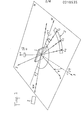
- a goniometer operating according to the SCHULZ principle.
- Such a goniometer comprises means for rotating a sample 1 around three axes Ox, Ou, Oz (rotations 4) ⁇ , ⁇ respectively), as shown diagrammatically in FIG. 1.
- the Ox axis is in the sample plane and in the incidence plane
- the Oz axis is perpendicular to the sample.
- the axis Oy which is perpendicular to the axes Ox and Oz and which completes the reference frame linked to the sample has also been shown.
- the normal OW to a family of reticular planes (hkl) is in the plane of incidence ⁇ and constitutes the bisector of the angle ( ⁇ - 2 ⁇ hkl ) defined by the radius R x and the diffracted ray directed towards the counter C 1 , the latter records the intensity of the diffraction by the planes (hkl) considered, as a function of the value of the angles ⁇ and y corresponding to rotations of the sample 1 around the axes Oz and Ox which are, respectively, perpendicular to the sample and located in the plane of it.
- the planes (hkl) of sample 1 can be brought, successively, to the BRAGG reflection position.
- the counter C 1 placed in position 2 ⁇ kh1 ' relative to the direction of the rays R x , records their density as a function of the angles ⁇ and y and it is then possible to trace the figure of poles corresponding to the planes (hkl).
- N pole figures If we place a set 3 of several (N) counters CI to C N in the incident plane ⁇ , or a curved counter whose plane of the circle is coincident with the plane of incidence ⁇ , and taking precautions concerning the location of the angles y and ⁇ as well as the necessary intensity corrections, it is possible to record, simultaneously, N pole figures.
- the time required to record these N pole figures is, however, not negligible, given the need to perform rotational movements of the sample 1 around two axes and to perform for each angle pair ( ⁇ , ⁇ ) a measure of intensity.
- the duration and the cost of the measures necessary for obtaining the distribution of the orientations of the crystallites are such that the texture analyzes are not as generalized as they could be.
- the present invention aims, precisely, to remedy the aforementioned drawbacks and to perform a texture analysis more quickly and less costly than according to the prior art by enabling the pole figure relating to a family of reticular planes (hkl) to be obtained by using only only one rotation.
- a method characterized in that the curved counter is placed in a plane perpendicular to the incident X-ray beam, in that the plane of the sample is oriented so that it defines a predetermined angle with respect to the incident X-ray beam, in that the curved counter is moved in translation parallel to the incident X-ray beam until the counter coincides with a section of the DEBYE cone defined by the beams of X-rays diffracted by the sample, in that one modifies the azimuthal position of the sample by rotation of the latter around an axis Oz perpendicular to the plane of the sample, in that one measures for each position on the counter and according to the angular position in azimuth of the sample the density of diffracted radiation and in that one establishes the position and the density of the normals to a family of reticular planes of the sample in the form of a po figure them from the measurements made with the meter.
- the azimuthal rotations of the sample can be performed step by step or continuously.
- the invention also relates to a device for determining the crystallographic texture of a polycrystalline material suitable for the method according to the invention, which comprises a sample support, an X-ray source, a curved scintillation counter multichannel, means for orienting the sample holder to orient the xOy plane of the sample with respect to the direction of the X-rays emitted by the radiation source, means for rotating the sample holder, so that the sample performs an azimuthal rotation around the normal Oz to the xOy plane of the sample, means for keeping the counter curved in a plane perpendicular to the direction of the X-rays emitted by the source and means for translating the counter curved parallel to the direction of the X-rays emitted by the source.
- the multichannel curved counter can comprise between approximately fifteen and thirty or more channels distributed over a portion of circumference extending over a sector of opening 90 °.
- the rotation of the sample is avoided for a family of reticular planes (hkl) both around an axis Ox located in the plane of the sample and around a perpendicular axis Oz in terms of the sample, which leads to a simplification of the measurement process and, at the same time, to a very significant reduction in the time necessary for carrying out the measurements.
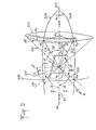
- the incident beam 211 of X-rays makes an angle ⁇ with the plane x0y of the sample 1 and is perpendicular to the plane of the circle 202 defined by the curved counter 30 intended to receive the radiation diffracted by the reticular planes of the sample 1.
- the counter 30 is placed at a distance L from the sample which is such that the active circle of the counter 30 coincides with the cone 201 of opening 2 ⁇ , called the DEBYE cone on which the X-ray beams are located 213 , 214 reflected by reticular planes (hkl).
- the counter 30 is moved in translation parallel to the direction of the incident beam 211, until the counter can capture part of the radiation reflected distributed on the DEBYE cone 201, that is to say until the arc of a circle defined by the curved counter 30, which is perpendicular to the beam 211, is coincident with part of a defined circle by the intersection of the cone 201 and a plane perpendicular to it.
- FIG. 2 there is shown the reference plane 203 defined by the incident beam 211 and the normal Oz to the sample 1, shown in phantom.
- the opening DEBYE cone 2 ⁇ hk1 is designated by the reference 201.
- the normals to the planes (hkl) giving reflection are on an opening cone - ⁇ and the place of the normals to the planes (hkl) is designated by the reference 205.
- the incidence plane 204 forms an angle ⁇ i with the reference plane 203.
- Point A. of the curved counter 30, located in the plane of incidence 204 sees the planes (hkl) of sample I whose normal 216, defined by ON i belongs to the plane of incidence 204 and makes an angle ⁇ i with the normal Oz to sample 1.
- the projection On '. 217 of the normal 216 in the plane of sample 1 makes an angle ⁇ o . with the axis Oy of the sample.
- the angles ⁇ i and ⁇ o are angles.
- ⁇ i is the angle between the incidence plane 204 containing the point A i considered of the counter and the reference plane 203 defined by the incident beam 211 of X-rays and the normal Oz to the sample
- ⁇ is the angle between sample 1 and incident beam 211 of X-rays
- 6 corresponds to the half-opening of the DEBYE 201 cone determined by BRAGG law.
- the point A i of the counter sees all the planes (hkl) of the sample whose normal 216 makes an angle y i with the normal Oz at l sample 1. It will be noted that the normal 216 constitutes the bisector of the angle defined by the incident beam 211 and the generator OA. 214.
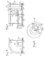
- Figs. 3 and 4 show an exemplary embodiment of a texture goniometer making it possible to implement the method defined with reference to FIG. 2.
- the frame 100, 102 of the goniometer rests on a table 110, by means of feet 101 forming adjustment shims.
- the sample 1 is mounted on the frame 100 using a support 11 making it possible to orient (rotation ⁇ ) the position of the sample 1 relative to the direction of an X-ray beam emitted by a source 20 provided with a collimator 22 and resting on the frame 100 by means of a stand 21.
- a device 12 also makes it possible to rotate the sample I around its normal Oz (rotation ⁇ ).
- a curved counter 30, the plane of the circle of which is perpendicular to the beam 211 of X-rays emitted by the source 20, rests by rollers 41, 42 on slides 43, 44, respectively, parallel to the direction of the beam 211, so to be able to move in translation parallel to the beam 211 and thus be able to pick up a DEBYE cone 201 ', 201 "relating to a given reticular plane (h'k'l'), (h" k "l”) respectively .
- a well 50 arranged in alignment with the X-ray beam 211, on the other side of the sample 1, makes it possible to receive the X-rays which pass through the sample 1 without deflection.
- Fig. 5 shows an exemplary embodiment of a texture goniometer whose general structure corresponds to the diagram in FIGS. 3 and 4.
- the X-ray source 120 comprising a collimator 122, is mounted on a support 121 and has a position which can be adjusted by means of adjustment knobs 123.
- the sample support 110 is mounted on a platform 114 which can slide along slides 115, 116 to be brought closer or distant from the source 120.
- the support 110 further comprises three sub-assemblies 111, 112, 113 making it possible to orient the sample according to three degrees of freedom, by rotation around of three axes of a reference frame linked to the support 110.
- the ring counter 130 has the shape of a third of a circle situated in a vertical plane perpendicular to the direction of emission of the X-ray beam by the collimator 122.
- the counter 130 can slide along two horizontal bars, upper 143 and lower 144, parallel to the direction of emission of the X-ray beam by the collimator 122.
- the curved counter is moved in translation relative to the sample. It must be considered that it would be equivalent to move the sample relative to the counter, such relative displacement may or may not be imposed on the X-ray source.
Landscapes
- Chemical & Material Sciences (AREA)
- Crystallography & Structural Chemistry (AREA)
- Physics & Mathematics (AREA)
- Health & Medical Sciences (AREA)
- Life Sciences & Earth Sciences (AREA)
- Analytical Chemistry (AREA)
- Biochemistry (AREA)
- General Health & Medical Sciences (AREA)
- General Physics & Mathematics (AREA)
- Immunology (AREA)
- Pathology (AREA)
- Analysing Materials By The Use Of Radiation (AREA)
Applications Claiming Priority (2)
| Application Number | Priority Date | Filing Date | Title |
|---|---|---|---|
| FR8514309 | 1985-09-24 | ||
| FR8514309A FR2587805B1 (fr) | 1985-09-24 | 1985-09-24 | Procede et dispositif de determination de la texture cristallographique d'un materiau polycristallin |
Publications (2)
| Publication Number | Publication Date |
|---|---|
| EP0218535A2 true EP0218535A2 (de) | 1987-04-15 |
| EP0218535A3 EP0218535A3 (de) | 1988-03-02 |
Family
ID=9323286
Family Applications (1)
| Application Number | Title | Priority Date | Filing Date |
|---|---|---|---|
| EP86420240A Withdrawn EP0218535A3 (de) | 1985-09-24 | 1986-09-23 | Verfahren und Vorrichtung zur Bestimmung der kristallinen Textur eines polykristallinen Materials |
Country Status (2)
| Country | Link |
|---|---|
| EP (1) | EP0218535A3 (de) |
| FR (1) | FR2587805B1 (de) |
Cited By (4)
| Publication number | Priority date | Publication date | Assignee | Title |
|---|---|---|---|---|
| DE4114582A1 (de) * | 1991-05-04 | 1992-11-05 | Inst Mechanik | Vorrichtung zur aufnahme eines prueflings in einem stationaeren diffraktometer |
| RU2366934C1 (ru) * | 2008-03-18 | 2009-09-10 | Открытое Акционерное Общество "Корпорация Всмпо-Ависма" | Способ определения кристаллографической текстуры осесимметричных заготовок |
| RU2390006C1 (ru) * | 2007-09-05 | 2010-05-20 | Нуктек Компани Лимитед | Установка и способ обнаружения контрабанды в авиационных грузовых контейнерах |
| CN115598157A (zh) * | 2021-06-25 | 2023-01-13 | 中国兵器工业第五九研究所(Cn) | 一种基于阵列探测的短波长特征x射线衍射装置和方法 |
Family Cites Families (2)
| Publication number | Priority date | Publication date | Assignee | Title |
|---|---|---|---|---|
| US4076981A (en) * | 1976-07-29 | 1978-02-28 | Syntex (U.S.A.) Inc. | Position sensitive area detector for use with X-ray diffractometer or X-ray camera |
| JPS55104747A (en) * | 1979-02-05 | 1980-08-11 | Rigaku Denki Kk | X-ray diffraction divice |
-
1985
- 1985-09-24 FR FR8514309A patent/FR2587805B1/fr not_active Expired
-
1986
- 1986-09-23 EP EP86420240A patent/EP0218535A3/de not_active Withdrawn
Cited By (4)
| Publication number | Priority date | Publication date | Assignee | Title |
|---|---|---|---|---|
| DE4114582A1 (de) * | 1991-05-04 | 1992-11-05 | Inst Mechanik | Vorrichtung zur aufnahme eines prueflings in einem stationaeren diffraktometer |
| RU2390006C1 (ru) * | 2007-09-05 | 2010-05-20 | Нуктек Компани Лимитед | Установка и способ обнаружения контрабанды в авиационных грузовых контейнерах |
| RU2366934C1 (ru) * | 2008-03-18 | 2009-09-10 | Открытое Акционерное Общество "Корпорация Всмпо-Ависма" | Способ определения кристаллографической текстуры осесимметричных заготовок |
| CN115598157A (zh) * | 2021-06-25 | 2023-01-13 | 中国兵器工业第五九研究所(Cn) | 一种基于阵列探测的短波长特征x射线衍射装置和方法 |
Also Published As
| Publication number | Publication date |
|---|---|
| FR2587805A1 (fr) | 1987-03-27 |
| FR2587805B1 (fr) | 1988-01-15 |
| EP0218535A3 (de) | 1988-03-02 |
Similar Documents
| Publication | Publication Date | Title |
|---|---|---|
| US11486699B2 (en) | Method for measuring the curvature of a reflective surface and associated optical device | |
| JP2002505750A (ja) | 角分散x線分光計 | |
| US5768335A (en) | Apparatus and method for measuring the orientation of a single crystal surface | |
| CN1620602A (zh) | 用于衍射分析的衍射仪及方法 | |
| EP0218535A2 (de) | Verfahren und Vorrichtung zur Bestimmung der kristallinen Textur eines polykristallinen Materials | |
| JPH1114561A (ja) | X線測定装置およびその方法 | |
| Deslattes | Single axis, two crystal x‐ray instrument | |
| EP0165877B1 (de) | Goniometervorrichtung für Röntgen- oder Neutronenstrahl-Diffraktometrie auf Monokristallen | |
| FR2607244A1 (fr) | Dispositif et methode de mesure de grille | |
| EP0241061A2 (de) | Vorrichtung zu Messung der Orientierung massiver Einkristallmaterialien mit Verwendung des Laue-Verfahrens | |
| US2798957A (en) | Reflection X-ray diffraction apparatus and method | |
| US6731719B2 (en) | X-ray diffractometer | |
| FR2831958A1 (fr) | Dispositif de plateau tournant destine a supporter et orienter une charge | |
| EP0115892B1 (de) | Röntgenuntersuchungsgerät mit einem doppelfokussierenden Kristall | |
| US3030507A (en) | X-ray apparatus for determination of internal stresses in materials | |
| US2556167A (en) | Crystal analysis apparatus | |
| Bauch et al. | X‐ray Rotation‐Tilt‐Method—First Results of a new X‐ray Diffraction Technique | |
| Ochs | Orienting and polishing single crystals for ultrasonic measurements | |
| FR3124272A1 (fr) | Dispositif de mesure du champ magnétique et procédé de mise en œuvre | |
| JP3245235B2 (ja) | 単結晶インゴットの結晶方位判別方法 | |
| Cotton et al. | EUV properties of two diffraction gratings | |
| Marais et al. | Alignment and calibration procedures of the Necsa neutron strain scanner | |
| EP0161992A2 (de) | Phasenanalyse-Apparatur durch Röntgenstrahl-Diffraktion auf texturierten oder nichttexturierten Proben mit einem elektronischen Photodetektor | |
| JP2620106B2 (ja) | 薄膜試料のx線回折極点図形観測装置 | |
| Otteson et al. | LINEAR-MOTION BENT-CRYSTAL GAMMA-RAY SPECTROMETER. |
Legal Events
| Date | Code | Title | Description |
|---|---|---|---|
| PUAI | Public reference made under article 153(3) epc to a published international application that has entered the european phase |
Free format text: ORIGINAL CODE: 0009012 |
|
| AK | Designated contracting states |
Kind code of ref document: A2 Designated state(s): AT BE CH DE GB IT LI LU NL SE |
|
| PUAL | Search report despatched |
Free format text: ORIGINAL CODE: 0009013 |
|
| AK | Designated contracting states |
Kind code of ref document: A3 Designated state(s): AT BE CH DE GB IT LI LU NL SE |
|
| 17P | Request for examination filed |
Effective date: 19881028 |
|
| 17Q | First examination report despatched |
Effective date: 19891026 |
|
| STAA | Information on the status of an ep patent application or granted ep patent |
Free format text: STATUS: THE APPLICATION IS DEEMED TO BE WITHDRAWN |
|
| 18D | Application deemed to be withdrawn |
Effective date: 19900613 |
|
| RIN1 | Information on inventor provided before grant (corrected) |
Inventor name: HEIZMANN, JEAN-JULIEN Inventor name: LARUELLE, CHRISTIAN |