EP0241061A2 - Vorrichtung zu Messung der Orientierung massiver Einkristallmaterialien mit Verwendung des Laue-Verfahrens - Google Patents
Vorrichtung zu Messung der Orientierung massiver Einkristallmaterialien mit Verwendung des Laue-Verfahrens Download PDFInfo
- Publication number
- EP0241061A2 EP0241061A2 EP87200403A EP87200403A EP0241061A2 EP 0241061 A2 EP0241061 A2 EP 0241061A2 EP 87200403 A EP87200403 A EP 87200403A EP 87200403 A EP87200403 A EP 87200403A EP 0241061 A2 EP0241061 A2 EP 0241061A2
- Authority
- EP
- European Patent Office
- Prior art keywords
- sample holder
- face
- plane
- sample
- parallel
- Prior art date
- Legal status (The legal status is an assumption and is not a legal conclusion. Google has not performed a legal analysis and makes no representation as to the accuracy of the status listed.)
- Withdrawn
Links
Images


Classifications
-
- G—PHYSICS
- G01—MEASURING; TESTING
- G01N—INVESTIGATING OR ANALYSING MATERIALS BY DETERMINING THEIR CHEMICAL OR PHYSICAL PROPERTIES
- G01N23/00—Investigating or analysing materials by the use of wave or particle radiation, e.g. X-rays or neutrons, not covered by groups G01N3/00 – G01N17/00, G01N21/00 or G01N22/00
- G01N23/20—Investigating or analysing materials by the use of wave or particle radiation, e.g. X-rays or neutrons, not covered by groups G01N3/00 – G01N17/00, G01N21/00 or G01N22/00 by using diffraction of the radiation by the materials, e.g. for investigating crystal structure; by using scattering of the radiation by the materials, e.g. for investigating non-crystalline materials; by using reflection of the radiation by the materials
- G01N23/20008—Constructional details of analysers, e.g. characterised by X-ray source, detector or optical system; Accessories therefor; Preparing specimens therefor
- G01N23/20025—Sample holders or supports therefor
Definitions
- the invention relates to a device for measuring the orientation of solid monocrystalline materials with respect to crystallographic landmarks by the Laüe method, formed on the one hand by a Laüe chamber including a polychromatic X-ray source, a support for photographic film and a collimator placed on the X-ray path between the source and the film near the latter defining the optical axis of the Laüe chamber, and formed on the other hand of support means for a massive sample, alignment means for the chamber and the support means, and means for locating the orientation of the sample relative to the crystallographic axes.
- the invention further relates to a method for producing a semiconductor device from a solid semiconductor monocrystalline ingot using this device.
- the invention finds its application in the measurement of the orientation of single crystals of new materials, such as for example semiconductors, to form crystals serving as pulling seeds, or to form platelets of substrates intended to receive epitaxial layers, orientation for which extreme precision is required.
- the invention finds a very particular application in the orientation of single crystals of III-V compounds such as for example gallium arsenide.
- Laue method is well known in the art, for example by the publication M lntroduction to the physics of solid state "by Kittel DUNOD-Editor 50-51.
- a single crystal is maintained motionless, in a polychromatic X-ray beam.
- the crystal only diffracts waves having lengths for which there are reticular planes separated by a distance and inclined with respect to the beam at an angle such that Bragg's law is verified.
- Each plane of the crystal selects, in the incident beam, a wavelength corresponding to the Bragg equation.
- the diagram obtained by the Laüe method consists of spots whose arrangement is characteristic of the symmetry of the crystal, and it can be used to orient the single crystal with respect to the crystallographic landmarks.
- a device for implementing the Laüe method is known from US patents 2,495,111, 2,543,160, 2,933,993, 2,483,389, 2,854,908 and the like, deposited by the company POLARO ⁇ D between 1949 and 1954.
- This device comprises, in addition to a support for a film, a collimator formed by a tube provided with a diaphragm at each end, fixed on a support perpendicular to the film and at a short distance from one of the faces of the latter, and a screen. said transformation fixed on the support parallel to the film and at a short distance from the other face of the latter.
- This transformation screen transforms X photons into visible photons for better use of POLAROID negative films which are not very sensitive to X-rays.
- a polychromatic beam coming from an X-ray source is directed towards the collimator, crosses the collimator, the negative film, then the transformation screen by a circular opening. practiced in the latter, before striking the crystal to be studied.
- the X-ray beam thus forms a spot on the film which constitutes the trace of the direct beam and which materializes the optical axis of the device.
- the rays reaching the crystal are diffracted by superficial crystal planes and return to the negative film support.
- the diffracted rays therefore strike the screen back transformation which transforms X into visible photons, which in turn impress the negative film, forming the diffraction pattern of the crystal, whose diagram of central spot is formed by the trace of the direct radiation beam X.
- the measurements giving the orientation of the crystal studied, relative to the crystallographic landmarks, are taken from the diagram made on the negative film, or on a positive taken from the negative film.
- the known device only allows relatively imprecise positioning of the various elements, such as the film support for example, and no information is provided concerning the positioning of the crystal to be characterized.
- the support means comprise at least one sample holder which has a first planar face for receiving the sample , a second plane face perpendicular to the first to block the sample, a first reference plane parallel to the first plane face, a second reference plane parallel to the second plane face and a third reference plane perpendicular to both the first and the second planar face
- the alignment means consist of an optical bench having at least two plane reference faces parallel to the optical axis of the Laüe
- the support means and the alignment means cooperate to provide the means for locating the orientation of the sample because the first and second reference planes of the optical bench support during the measurement the set chosen from the first and the second, or else the first and the third reference plane of the sample holder.
- This device can also be characterized in that, when the first and second reference planes of the optical bench support the assembly of the first and second reference planes of the sample holder, the first planar face and the second face plane of this sample holder are adjusted relative to the optical axis of the Laüe chamber at a distance from this axis substantially equal to the mean radius of the sample.
- the support means further comprise a disc holder which has a first planar face, and a second planar face perpendicular to the first for pressing and blocking the edge of a monocrystalline disc cut in a ingot, a third plane face perpendicular to the first two to receive one of the faces of the disc, a first reference plane parallel to the first plane face, and a second reference plane parallel to the second plane face, and in that the disc holder cooperates with the sample holder and with the alignment means to provide the means for locating the orientation of the disc, since, during the measurement, the first and second reference planes of the disc holder are supported on the first and second planar faces of the sample holder, and the fact that the first and second reference planes of the optical bench support the first and third reference planes of the sample holder not.
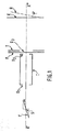
- the X-rays from the source S pass through the collimator C and the transformation screen T through an opening D 3 of diameter greater than the opening of the diaphragms D 1 and D 2 of the collimator.
- the rays which reach the sample are diffracted for example by a reticular plane R which makes an angle ⁇ with the surface of the sample E.
- the diffracted rays then return to the negative film support. They strike back the transformation screen T which transforms the photons X into visible ones which in turn impress the negative film, forming the diffraction diagram of the single crystal, diagram whose central spot is formed by the trace of the direct beam of X-rays .
- the X-ray source S, the collimator C, the film plane support P, the transformation screen T and a sample holder for the sample E are mounted on a bench high precision optics, this bench itself being mounted on a "marble” also of high precision. These elements are also aligned optically along the axis X'X ".
- They can also be group III-V monocrystalline compounds such as gallium arsenide, a relatively new compound compared to silicon and for which many problems still remain to be solved.
- group IV semiconductor single crystals such as germanium and silicon, or group III-V such as gallium arsenide, are generally obtained by growth from a molten bath by a method of the Czochralsky type for example, from '' a carefully oriented seed germ.
- This cylinder most often has a standard diameter, expressed in the old Anglo-Saxon units, which is 2 inches, that is to say approximately 51 mm, or else 3 inches, that is to say approximately 76 mm.
- these cylinders must have a locating flat made according to a crystallographic facet chosen conventionally between manufacturers and users.
- Thin disks are further cut from these cylinders, for application to integrated circuits for example, perpendicular to the axis of symmetry of the cylinder.
- the trace of the cylinder flat forms on the discs a cutaway which allows the location of the orientation of the each disc, this orientation being very important because these materials generally have anisotropic properties.
- the precision of the orientation of the axis of the cylinder depends on the precision of the parallel faces of the discs, and therefore the quality of the layers, for example epitaxial or implanted, produced subsequently.
- the orientation of the flat surface depends on the orientation of the active and passive devices produced on the disks used as substrate of integrated circuits, and therefore the performance of said circuits, since these performances depend on the orientation of the elements due to the anisotropy of material properties.
- the device known from the state of the art under the name of Laüe chamber makes it possible to determine the orientation of the single crystals which are subjected to this method.
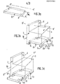
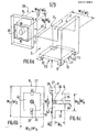
- This sample holder 10 comprises a first planar face 1 and a second planar face 2 which is perpendicular to the first.
- planar faces are machined with great precision in a solid metal block.
- This solid metal block also has, in its base, grooves 112 and 113 which determine a reference plane 11 parallel to the first flat face 1. These grooves further determine reference planes 12 and 13, the reference plane 12 being parallel to the plane face 2 and the reference plane 13 being perpendicular to both the plane faces 1 and 2.
- the grooves 112 and 113 thus determine in the block 10 feet 5 of height h whose internal faces constitute the planes 12 and 13.
- the dimension of the grooves 112 and 113 is W 4 . These grooves are provided to allow the sample holder 10 to overlap an optical bench B shown in perspective in FIG. 3a.
- the optical bench B comprises a first reference plane 21, of dimension W 4 , to support on the one hand the Laüe chamber, and on the other hand the sample holder.
- Laüe's chamber is fixed on the optical bench B in such a way that its optical axis X'X "is perpendicular to the dimension W 4 of the optical bench and parallel to its surface 21.
- the optical bench B further comprises a second reference plane 22 perpendicular to the plane 21. Under these conditions the sample holder 10 can be placed on the optical bench so that the reference plane 11 of the sample holder take support on the reference plane 21 of bench B and that either the reference plane 12 or the reference plane 13 is supported on the reference plane 22 of bank B.
- the dimension of the grooves 112 and 113 is therefore also provided for dimension W 4 , but with a clearance just sufficient for the sliding of the sample holder on the optical bench B, the feet 5 blocking the sample holder on the bench.
- the dimension of the reference plane 22 of the optical bench parallel to the dimension h of the feet 5 is provided greater than this dimension h.
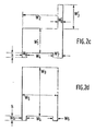
- the sample holder 10 can be placed in position on the bench B also in two perpendicular directions, as shown in FIGS. 3b and 3c.
- the sample holder 10 is placed on the bench B in such a way that the reference plane 11 is supported on the reference plane 21 of the bench B, the reference plane 13 is supported on the reference plane 22.
- the optical axis X'X "being perpendicular to the dimension W 4 of the bench, is then perpendicular to the plane face 2 of the latter.
- the sample holder 10 is placed on the bench B in such a way that the reference plane 11 is supported on the reference plane 21 of the bench B, the reference plane 12 is supported on the reference plane 22.
- the optical axis X'X "being perpendicular to the dimension W 4 of the bench, is then parallel both to the planar face 2 and to the planar face 1 of the latter.
- FIG. 2d represents one or the other of the sample holders for one or other of these applications seen from the side of the backsplash formed by the opposite of the flat face 2.
- sample holder according to the invention can be advantageously machined in a solid metallic block of DURAL (registered trademark), stainless steel or gilded bronze.
- the dimensions of the sample holders are provided such that in the longitudinal or transverse position, the plane of symmetry of the reference face 1, which is the carrier face of the sample, is coincident with the plane of symmetry of the optical bench, with that of the sample and also contains the optical axis, the sample being pressed against the flat face 2.
- these dimensions are provided such that, in the longitudinal position, the first planar face 1 and the second planar face 2 are adjusted at a distance from the optical axis X'X "substantially equal to the mean radius of the sample.
- a method for carrying out the orientation of a solid ingot using a Laüe chamber provided with the sample holder according to the invention is described below, the solid ingot being a single crystal of gallium arsenide taken at as an example.
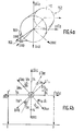
- Figure 4a shows an ingot 150 of raw draft gallium arsenide.
- This ingot which is approximately cylindrical, has a part of smaller diameter which corresponds to the initiation of the drawing from a carefully oriented germ.
- This small diameter part is called “head” 151 of the ingot.
- the opposite part is called “tail” 152.
- the drawing is carried out along the crystallographic axis [100]. The other crystallographic axes are then placed respectively as shown in FIG. 4a.
- a facet 153 is first produced perpendicular to the drawing axis, on the head side of the ingot, either by breakage or by sawing.
- the ingot is placed on the sample holder 10 so that the drawing axis is parallel to both sides 1 and 2.
- the ingot is supported on each of the sides 1 and 2, because it is almost cylindrical.
- the sample holder 10 is placed on the optical bench B in the so-called "longitudinal" position.
- the faces 1 and 2 are both parallel to the optical axis X'X ", and this optical axis is perpendicular to the face 153.
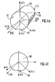
- a Laüe diagram is carried out under these conditions and the ingot is rotated on the sample holder until the axis [011] is perpendicular to face 1 and the axis [011] is perpendicular to face 2 of the sample carrier.
- the axes must be marked in relation to the frame of the film plane on which the diagram is saved.
- This frame is embodied by the straight line IJ in FIG. 4b, and is roughly parallel to the face 1 of the sample holder.
- a flat 55 is machined perpendicular to the axis [011].
- the measurement can then be repeated by resting the flat on the face 1 of the sample holder, the facet 153 being moreover oriented in the same way as above.
- the orientation of the flat part 55 is touched up by machining until the precision on its orientation is of the order of ⁇ 1 °.
- machining of the ingot is then carried out to obtain a cylinder 50 with an axis parallel to the drawing axis, as shown in FIG. 4c.
- the measurements are made on Laüe diagrams obtained by dropping the X-ray beam on a generator of the cylinder 50.
- this cylinder 50 is placed on the sample holder 10 so that the flat 55 rests on the face 1 and that a generator is pressed against the face 2.
- the sample holder is placed on the ban B so that the face 2 is perpendicular to the optical axis X'X ", and that the X-ray beam falls on a generator of the cylinder, that is to say in a position defined as transverse.
- the precision on the measurements is obtained by a double measurement carried out by turning the cylinder 50 by 180 ° on the sample holder 10, the flat 55 being always placed on the face 1. This double measurement makes it possible to verify the reproducibility of the photographs compared to the reference of the edge of the plane-film support, but in relative measurement and not in absolute measurement.
- thin disks 60 are cut in the cylinder 50 perpendicular to the axis.
- the flat 56 formed in the cylinder constitutes, as we have seen, a cutaway 65 of reference on each disc.
- a second part 20 is then added to the sample holder 10 to measure the orientation of the faces of the thin disks cut in the cylinder.
- the second part of the sample holder, or disc holder 20 is composed of a body 9 parallelepiped, having reference planes 31, 32, 33 perpendicular to each other.
- the planes 31 and 32 of the disc holder are intended to be placed in coincidence with the planar faces 1 and 2 respectively, of the sample holder.
- the planes 31 and 32 of the disc holder have the dimensions W 5 x W 10
- the planes 31 and 32 have the dimensions W 5 x W '10 .
- the body 9 also includes a central recess 36 to allow its connection to a vacuum device not shown, for example by means of a pipe 46.
- This body 9 is provided parallel to the reference plane 33 with a flange 8 of imprecise dimension, W 11 or W ′ 11 , simply protruding beyond the faces 31 and 32 so that, when the body 9 is in place on the sample holder 10, this flange 8 blocks the disc holder against the side 3 of the sample holder.
- This flange 8 is provided with a square recess which uncovers the planar face 43 parallel to the reference plane 33.
- This planar face 43 has dimensions W 10 x W 10 for receiving discs of diameter W 10 , or dimensions W '10 x W 10 to the diameter of disk W '10.
- the depth of the square recess is e equivalent to the thickness of a disc 60.
- This planar face 43 is shaped with great precision on the flatness.
- a plug is placed with a body that is both rigid and porous 26, so that the bottom of the recess 43 is perfectly flat.
- the puddle 8 is further provided with fixing lugs 27 and 28 held for example by screws.
- the disc 60 cut from the cylinder 50 is placed in the square recess against the flat face 43, is held by the tabs 27 and 28, and is pressed against the bottom of the square recess by placing under vacuum of the recess 36.
- the plug 26 of rigid and porous material prevents deformation of the disc 60 during this evacuation.
- the body 9 is placed in position on the sample holder so that its faces 31 and 32 coincide respectively with sides 1 and 2 of the sample holder.
- the sample holder is then placed on the optical bench B in such a way that the optical axis X'X "is parallel to the faces 1 and 2, and perpendicular to the disc 60 placed in the recess 43, c ' that is to say in a position defined as longitudinal.
- the cutaway 65 is pressed against one of the edges 41 or 42 of the recess 43. These edges 41 and 42 form flat faces parallel to the flat faces 1 and 2 respectively and serve as a reference for the production of the Laüe diagram.
- Table II gives the dimensions for the disc holder as an example of embodiment.
- the material for making the holder 20 can be chosen from the materials mentioned for making the sample holder.
- the material for producing the rigid and porous plug 26 may advantageously be sintered bronze.
Landscapes
- Chemical & Material Sciences (AREA)
- Crystallography & Structural Chemistry (AREA)
- Physics & Mathematics (AREA)
- Health & Medical Sciences (AREA)
- Life Sciences & Earth Sciences (AREA)
- Analytical Chemistry (AREA)
- Biochemistry (AREA)
- General Health & Medical Sciences (AREA)
- General Physics & Mathematics (AREA)
- Immunology (AREA)
- Pathology (AREA)
- Analysing Materials By The Use Of Radiation (AREA)
- Crystals, And After-Treatments Of Crystals (AREA)
Applications Claiming Priority (2)
| Application Number | Priority Date | Filing Date | Title |
|---|---|---|---|
| FR8603818A FR2596154B1 (fr) | 1986-03-18 | 1986-03-18 | Dispositif pour la mesure de l'orientation de materiaux massifs monocristallins par la methode de laue |
| FR8603818 | 1986-03-18 |
Publications (2)
| Publication Number | Publication Date |
|---|---|
| EP0241061A2 true EP0241061A2 (de) | 1987-10-14 |
| EP0241061A3 EP0241061A3 (de) | 1990-03-07 |
Family
ID=9333218
Family Applications (1)
| Application Number | Title | Priority Date | Filing Date |
|---|---|---|---|
| EP87200403A Withdrawn EP0241061A3 (de) | 1986-03-18 | 1987-03-05 | Vorrichtung zu Messung der Orientierung massiver Einkristallmaterialien mit Verwendung des Laue-Verfahrens |
Country Status (4)
| Country | Link |
|---|---|
| US (1) | US4862488A (de) |
| EP (1) | EP0241061A3 (de) |
| JP (1) | JPS62220848A (de) |
| FR (1) | FR2596154B1 (de) |
Families Citing this family (9)
| Publication number | Priority date | Publication date | Assignee | Title |
|---|---|---|---|---|
| JP2569862B2 (ja) * | 1990-02-13 | 1997-01-08 | 三菱電機株式会社 | X線露光装置およびx線露光方法 |
| US6055293A (en) * | 1998-06-30 | 2000-04-25 | Seh America, Inc. | Method for identifying desired features in a crystal |
| US6507636B1 (en) * | 2000-02-10 | 2003-01-14 | Studiengesellschaft Kohle Mbh | Rapid X-ray diffraction screening method of polymorph libraries created in multi-well plates |
| GB0031040D0 (en) * | 2000-12-20 | 2001-01-31 | Koninkl Philips Electronics Nv | X-ray diffractometer |
| US6760403B2 (en) | 2001-10-25 | 2004-07-06 | Seh America, Inc. | Method and apparatus for orienting a crystalline body during radiation diffractometry |
| US7027557B2 (en) * | 2004-05-13 | 2006-04-11 | Jorge Llacer | Method for assisted beam selection in radiation therapy planning |
| US7237438B1 (en) | 2005-03-16 | 2007-07-03 | United Technologies Corporation | Systems and methods for determining the velocity of ultrasonic surface skimming longitudinal waves on various materials |
| US7978821B1 (en) | 2008-02-15 | 2011-07-12 | The United States Of America As Represented By The Secretary Of The Air Force | Laue crystallographic orientation mapping system |
| US10031286B1 (en) * | 2016-06-14 | 2018-07-24 | Onyx Optics, Inc. | Waveguide structures in anisotropic lasing and nonlinear optical media |
Family Cites Families (13)
| Publication number | Priority date | Publication date | Assignee | Title |
|---|---|---|---|---|
| DE217889C (de) * | ||||
| US2904688A (en) * | 1958-06-06 | 1959-09-15 | Super Cut | Cassette and holder therefor for back reflection cameras |
| US3078559A (en) * | 1959-04-13 | 1963-02-26 | Sylvania Electric Prod | Method for preparing semiconductor elements |
| FR1575196A (de) * | 1967-08-05 | 1969-07-18 | ||
| US3600575A (en) * | 1969-05-05 | 1971-08-17 | Frank L Chan | Crystal mount and goniometer for taking laue patterns and for orientation of large single crystals |
| US3631239A (en) * | 1970-06-24 | 1971-12-28 | Avco Corp | Specimen alignment reference apparatus for back reflection x-ray camera |
| US3716712A (en) * | 1971-09-27 | 1973-02-13 | Northern Electric Co | Apparatus for and method of orienting crystal wafers |
| US4228578A (en) * | 1979-01-15 | 1980-10-21 | Monsanto Company | Method for off-orientation point rotation sawing of crystalline rod material |
| SU805419A1 (ru) * | 1979-03-14 | 1981-02-15 | Институт Кристаллографии Им.А.В.Шубникова Ah Cccp | Способ изготовлени монохромато-PA РЕНТгЕНОВСКОгО излучЕНи |
| US4217493A (en) * | 1979-06-04 | 1980-08-12 | The United States Of America As Represented By The United States Department Of Energy | Hemispherical Laue camera |
| GB8325544D0 (en) * | 1983-09-23 | 1983-10-26 | Howe S H | Orienting crystals |
| US4547958A (en) * | 1984-05-16 | 1985-10-22 | The United States Of America As Represented By The Secretary Of The Air Force | VMJ Solar cell fabrication process using mask aligner |
| GB8607482D0 (en) * | 1986-03-26 | 1986-04-30 | Howe S | Orientation of crystals |
-
1986
- 1986-03-18 FR FR8603818A patent/FR2596154B1/fr not_active Expired
-
1987
- 1987-02-20 US US07/017,391 patent/US4862488A/en not_active Expired - Fee Related
- 1987-03-05 EP EP87200403A patent/EP0241061A3/de not_active Withdrawn
- 1987-03-18 JP JP62061390A patent/JPS62220848A/ja active Pending
Also Published As
| Publication number | Publication date |
|---|---|
| FR2596154A1 (fr) | 1987-09-25 |
| FR2596154B1 (fr) | 1988-05-13 |
| US4862488A (en) | 1989-08-29 |
| EP0241061A3 (de) | 1990-03-07 |
| JPS62220848A (ja) | 1987-09-29 |
Similar Documents
| Publication | Publication Date | Title |
|---|---|---|
| EP0802029B1 (de) | Verfahren zum Orientieren von mehreren Einkristallbarren auf einem Träger für das gleichzeitige Aufschneiden der Barren in einer Schneidmaschine | |
| EP0738572B1 (de) | Verfahren zur Orientierung von Einkristallen zum Schneiden in eine Schneidemaschine und Einrichtung zur Durchführung des Verfahrens | |
| US5032734A (en) | Method and apparatus for nondestructively measuring micro defects in materials | |
| EP0439881B1 (de) | Verfahren und Vorrichtung zur störungsfreien Messung von Mikrofehlern in Materialien | |
| US4978862A (en) | Method and apparatus for nondestructively measuring micro defects in materials | |
| US4352016A (en) | Method and apparatus for determining the quality of a semiconductor surface | |
| EP0320326B1 (de) | Verfahren und Gerät zur kontaktlosen Regelung von geometrischen Abmessungen | |
| EP0241061A2 (de) | Vorrichtung zu Messung der Orientierung massiver Einkristallmaterialien mit Verwendung des Laue-Verfahrens | |
| FR2888043A1 (fr) | Capteur d'image a galette de fibres optiques | |
| LU87933A1 (fr) | Procede et dispositif d'etalonnage d'un pyrometre optique et plaquettes etalons correspondantes | |
| Mandelis et al. | Absolute nonradiative energy-conversion-efficiency spectra in Ti 3+: Al 2 O 3 crystals measured by noncontact quadrature photopyroelectric spectroscopy | |
| Welzel et al. | Use of polycapillary X-ray lenses in the X-ray diffraction measurement of texture | |
| CN1834623A (zh) | 半导体材料残余应力的测试装置及方法 | |
| EP0413639B1 (de) | Zusammenbau von Teilen mit einem gegenseitigen Winkel und Verfahren zur Herstellung | |
| EP0191530A1 (de) | Laue-Kammer | |
| EP0218535A2 (de) | Verfahren und Vorrichtung zur Bestimmung der kristallinen Textur eines polykristallinen Materials | |
| FR2504256A1 (fr) | Procede et dispositif de mesure optique de deplacement et application aux photorepeteurs sur tranche | |
| JP2890588B2 (ja) | 膜厚の測定方法 | |
| EP1062670B1 (de) | Verfahren zum zusammenstellen einer optischen einheit mit koaxialen schalen, insbesondere für ein röntgenteleskop | |
| KR20120084090A (ko) | 실리콘 단결정의 비축을 이용한 x선 회절용 무반사 샘플홀더, 그 샘플홀더의 제조방법, 그 샘플홀더를 포함하는 x선 회절분석시스템 및 회절분석방법 | |
| EP3764388A1 (de) | Verfahren zur analyse durch elektronenmikroskopie | |
| US20040064263A1 (en) | System and method for measuring properties of a semiconductor substrate in a non-destructive way | |
| FR2602043A1 (fr) | Procede de mesure non destructive du profil d'une surface | |
| WO2021180347A1 (fr) | Dispositif de détection pour microscope à sonde locale | |
| WO2012085401A1 (fr) | Dispositif de mesure d'un degre de desalignement et procede d'utilisation dudit dispositif |
Legal Events
| Date | Code | Title | Description |
|---|---|---|---|
| PUAI | Public reference made under article 153(3) epc to a published international application that has entered the european phase |
Free format text: ORIGINAL CODE: 0009012 |
|
| AK | Designated contracting states |
Kind code of ref document: A2 Designated state(s): CH DE FR GB IT LI NL |
|
| PUAL | Search report despatched |
Free format text: ORIGINAL CODE: 0009013 |
|
| RAP1 | Party data changed (applicant data changed or rights of an application transferred) |
Owner name: N.V. PHILIPS' GLOEILAMPENFABRIEKEN Owner name: LABORATOIRES D'ELECTRONIQUE PHILIPS |
|
| AK | Designated contracting states |
Kind code of ref document: A3 Designated state(s): CH DE FR GB IT LI NL |
|
| 17P | Request for examination filed |
Effective date: 19900904 |
|
| 17Q | First examination report despatched |
Effective date: 19920311 |
|
| STAA | Information on the status of an ep patent application or granted ep patent |
Free format text: STATUS: THE APPLICATION IS DEEMED TO BE WITHDRAWN |
|
| 18D | Application deemed to be withdrawn |
Effective date: 19930713 |
|
| RIN1 | Information on inventor provided before grant (corrected) |
Inventor name: SCHILLER, CLAUDESOCIETE CIVILE S.P.I.D. |