EP0218535A2 - Method and device for determining the crystallographic texture of a polycrystalline material - Google Patents
Method and device for determining the crystallographic texture of a polycrystalline material Download PDFInfo
- Publication number
- EP0218535A2 EP0218535A2 EP86420240A EP86420240A EP0218535A2 EP 0218535 A2 EP0218535 A2 EP 0218535A2 EP 86420240 A EP86420240 A EP 86420240A EP 86420240 A EP86420240 A EP 86420240A EP 0218535 A2 EP0218535 A2 EP 0218535A2
- Authority
- EP
- European Patent Office
- Prior art keywords
- sample
- counter
- plane
- curved
- incident
- Prior art date
- Legal status (The legal status is an assumption and is not a legal conclusion. Google has not performed a legal analysis and makes no representation as to the accuracy of the status listed.)
- Withdrawn
Links
Images

Classifications
-
- G—PHYSICS
- G01—MEASURING; TESTING
- G01N—INVESTIGATING OR ANALYSING MATERIALS BY DETERMINING THEIR CHEMICAL OR PHYSICAL PROPERTIES
- G01N23/00—Investigating or analysing materials by the use of wave or particle radiation, e.g. X-rays or neutrons, not covered by groups G01N3/00 – G01N17/00, G01N21/00 or G01N22/00
- G01N23/20—Investigating or analysing materials by the use of wave or particle radiation, e.g. X-rays or neutrons, not covered by groups G01N3/00 – G01N17/00, G01N21/00 or G01N22/00 by using diffraction of the radiation by the materials, e.g. for investigating crystal structure; by using scattering of the radiation by the materials, e.g. for investigating non-crystalline materials; by using reflection of the radiation by the materials
- G01N23/207—Diffractometry using detectors, e.g. using a probe in a central position and one or more displaceable detectors in circumferential positions
Definitions
- the present invention relates to a method for determining the crystallographic texture of a polycrystalline material according to which a sample of the material to be analyzed is positioned with respect to an incident X-ray beam and the X-ray beam diffracted by the sample is analyzed. using a scintillation counter of the multi-channel curved counter type.
- This anisotropy is a function of the anisotropy of the crystal itself, but also of the distribution of the orientations of the crystallites constituting the material.
- the crystallographic texture corresponds to this distribution of the orientations of the crystallites in the material. It plays a very important role, on the one hand, to know the properties of the material, on the other hand, to predict the evolution of its properties, in particular mechanical, physical and chemical.
- a certain anisotropy of the material can be sought to give the material specific properties (magnetic sheets). but in other cases this anisotropy can become undesirable (drawing horns).
- a goniometer operating according to the SCHULZ principle.
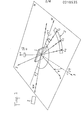
- Such a goniometer comprises means for rotating a sample 1 around three axes Ox, Ou, Oz (rotations 4) ⁇ , ⁇ respectively), as shown diagrammatically in FIG. 1.
- the Ox axis is in the sample plane and in the incidence plane
- the Oz axis is perpendicular to the sample.
- the axis Oy which is perpendicular to the axes Ox and Oz and which completes the reference frame linked to the sample has also been shown.
- the normal OW to a family of reticular planes (hkl) is in the plane of incidence ⁇ and constitutes the bisector of the angle ( ⁇ - 2 ⁇ hkl ) defined by the radius R x and the diffracted ray directed towards the counter C 1 , the latter records the intensity of the diffraction by the planes (hkl) considered, as a function of the value of the angles ⁇ and y corresponding to rotations of the sample 1 around the axes Oz and Ox which are, respectively, perpendicular to the sample and located in the plane of it.
- the planes (hkl) of sample 1 can be brought, successively, to the BRAGG reflection position.
- the counter C 1 placed in position 2 ⁇ kh1 ' relative to the direction of the rays R x , records their density as a function of the angles ⁇ and y and it is then possible to trace the figure of poles corresponding to the planes (hkl).
- N pole figures If we place a set 3 of several (N) counters CI to C N in the incident plane ⁇ , or a curved counter whose plane of the circle is coincident with the plane of incidence ⁇ , and taking precautions concerning the location of the angles y and ⁇ as well as the necessary intensity corrections, it is possible to record, simultaneously, N pole figures.
- the time required to record these N pole figures is, however, not negligible, given the need to perform rotational movements of the sample 1 around two axes and to perform for each angle pair ( ⁇ , ⁇ ) a measure of intensity.
- the duration and the cost of the measures necessary for obtaining the distribution of the orientations of the crystallites are such that the texture analyzes are not as generalized as they could be.
- the present invention aims, precisely, to remedy the aforementioned drawbacks and to perform a texture analysis more quickly and less costly than according to the prior art by enabling the pole figure relating to a family of reticular planes (hkl) to be obtained by using only only one rotation.
- a method characterized in that the curved counter is placed in a plane perpendicular to the incident X-ray beam, in that the plane of the sample is oriented so that it defines a predetermined angle with respect to the incident X-ray beam, in that the curved counter is moved in translation parallel to the incident X-ray beam until the counter coincides with a section of the DEBYE cone defined by the beams of X-rays diffracted by the sample, in that one modifies the azimuthal position of the sample by rotation of the latter around an axis Oz perpendicular to the plane of the sample, in that one measures for each position on the counter and according to the angular position in azimuth of the sample the density of diffracted radiation and in that one establishes the position and the density of the normals to a family of reticular planes of the sample in the form of a po figure them from the measurements made with the meter.
- the azimuthal rotations of the sample can be performed step by step or continuously.
- the invention also relates to a device for determining the crystallographic texture of a polycrystalline material suitable for the method according to the invention, which comprises a sample support, an X-ray source, a curved scintillation counter multichannel, means for orienting the sample holder to orient the xOy plane of the sample with respect to the direction of the X-rays emitted by the radiation source, means for rotating the sample holder, so that the sample performs an azimuthal rotation around the normal Oz to the xOy plane of the sample, means for keeping the counter curved in a plane perpendicular to the direction of the X-rays emitted by the source and means for translating the counter curved parallel to the direction of the X-rays emitted by the source.
- the multichannel curved counter can comprise between approximately fifteen and thirty or more channels distributed over a portion of circumference extending over a sector of opening 90 °.
- the rotation of the sample is avoided for a family of reticular planes (hkl) both around an axis Ox located in the plane of the sample and around a perpendicular axis Oz in terms of the sample, which leads to a simplification of the measurement process and, at the same time, to a very significant reduction in the time necessary for carrying out the measurements.
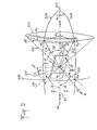
- the incident beam 211 of X-rays makes an angle ⁇ with the plane x0y of the sample 1 and is perpendicular to the plane of the circle 202 defined by the curved counter 30 intended to receive the radiation diffracted by the reticular planes of the sample 1.
- the counter 30 is placed at a distance L from the sample which is such that the active circle of the counter 30 coincides with the cone 201 of opening 2 ⁇ , called the DEBYE cone on which the X-ray beams are located 213 , 214 reflected by reticular planes (hkl).
- the counter 30 is moved in translation parallel to the direction of the incident beam 211, until the counter can capture part of the radiation reflected distributed on the DEBYE cone 201, that is to say until the arc of a circle defined by the curved counter 30, which is perpendicular to the beam 211, is coincident with part of a defined circle by the intersection of the cone 201 and a plane perpendicular to it.
- FIG. 2 there is shown the reference plane 203 defined by the incident beam 211 and the normal Oz to the sample 1, shown in phantom.
- the opening DEBYE cone 2 ⁇ hk1 is designated by the reference 201.
- the normals to the planes (hkl) giving reflection are on an opening cone - ⁇ and the place of the normals to the planes (hkl) is designated by the reference 205.
- the incidence plane 204 forms an angle ⁇ i with the reference plane 203.
- Point A. of the curved counter 30, located in the plane of incidence 204 sees the planes (hkl) of sample I whose normal 216, defined by ON i belongs to the plane of incidence 204 and makes an angle ⁇ i with the normal Oz to sample 1.
- the projection On '. 217 of the normal 216 in the plane of sample 1 makes an angle ⁇ o . with the axis Oy of the sample.
- the angles ⁇ i and ⁇ o are angles.
- ⁇ i is the angle between the incidence plane 204 containing the point A i considered of the counter and the reference plane 203 defined by the incident beam 211 of X-rays and the normal Oz to the sample
- ⁇ is the angle between sample 1 and incident beam 211 of X-rays
- 6 corresponds to the half-opening of the DEBYE 201 cone determined by BRAGG law.
- the point A i of the counter sees all the planes (hkl) of the sample whose normal 216 makes an angle y i with the normal Oz at l sample 1. It will be noted that the normal 216 constitutes the bisector of the angle defined by the incident beam 211 and the generator OA. 214.
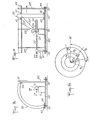
- Figs. 3 and 4 show an exemplary embodiment of a texture goniometer making it possible to implement the method defined with reference to FIG. 2.
- the frame 100, 102 of the goniometer rests on a table 110, by means of feet 101 forming adjustment shims.
- the sample 1 is mounted on the frame 100 using a support 11 making it possible to orient (rotation ⁇ ) the position of the sample 1 relative to the direction of an X-ray beam emitted by a source 20 provided with a collimator 22 and resting on the frame 100 by means of a stand 21.
- a device 12 also makes it possible to rotate the sample I around its normal Oz (rotation ⁇ ).
- a curved counter 30, the plane of the circle of which is perpendicular to the beam 211 of X-rays emitted by the source 20, rests by rollers 41, 42 on slides 43, 44, respectively, parallel to the direction of the beam 211, so to be able to move in translation parallel to the beam 211 and thus be able to pick up a DEBYE cone 201 ', 201 "relating to a given reticular plane (h'k'l'), (h" k "l”) respectively .
- a well 50 arranged in alignment with the X-ray beam 211, on the other side of the sample 1, makes it possible to receive the X-rays which pass through the sample 1 without deflection.
- Fig. 5 shows an exemplary embodiment of a texture goniometer whose general structure corresponds to the diagram in FIGS. 3 and 4.
- the X-ray source 120 comprising a collimator 122, is mounted on a support 121 and has a position which can be adjusted by means of adjustment knobs 123.
- the sample support 110 is mounted on a platform 114 which can slide along slides 115, 116 to be brought closer or distant from the source 120.
- the support 110 further comprises three sub-assemblies 111, 112, 113 making it possible to orient the sample according to three degrees of freedom, by rotation around of three axes of a reference frame linked to the support 110.
- the ring counter 130 has the shape of a third of a circle situated in a vertical plane perpendicular to the direction of emission of the X-ray beam by the collimator 122.
- the counter 130 can slide along two horizontal bars, upper 143 and lower 144, parallel to the direction of emission of the X-ray beam by the collimator 122.
- the curved counter is moved in translation relative to the sample. It must be considered that it would be equivalent to move the sample relative to the counter, such relative displacement may or may not be imposed on the X-ray source.
Abstract
Description
La présente invention concerne un procédé de détermination de la texture cristallographique d'un matériau polycristallin selon lequel on positionne un échantillon du matériau à analyser par rapport à un faisceau de rayons X incident et on analyse le faisceau de rayons X diffracté par l'échantillon à l'aide d'un compteur à scintillation du type compteur courbe multicanaux.The present invention relates to a method for determining the crystallographic texture of a polycrystalline material according to which a sample of the material to be analyzed is positioned with respect to an incident X-ray beam and the X-ray beam diffracted by the sample is analyzed. using a scintillation counter of the multi-channel curved counter type.
La plupart des matériaux utilisés sont polycristallins. Les propriétés de tels matériaux sont, généralement, anisotropes, c'est-à-dire que ces propriétés sont différentes selon la direction d'observation ou de mesure.Most of the materials used are polycrystalline. The properties of such materials are, generally, anisotropic, that is to say that these properties are different depending on the direction of observation or measurement.
Cette anisotropie est fonction de l'anisotropie même du cristal, mais aussi de la distribution des orientations des cristallites constituant le matériau.This anisotropy is a function of the anisotropy of the crystal itself, but also of the distribution of the orientations of the crystallites constituting the material.
La texture cristallographique correspond à cette distribution des orientations des cristallites dans le matériau. Elle joue un rôle très important, d'une part, pour connaître les propriétés du matériau, d'autre part, pour prévoir l'évolution de ses propriétés, notamment mécaniques, physiques et chimiques.The crystallographic texture corresponds to this distribution of the orientations of the crystallites in the material. It plays a very important role, on the one hand, to know the properties of the material, on the other hand, to predict the evolution of its properties, in particular mechanical, physical and chemical.
Une certaine anisotropie du matériau peut être recherchée pour donner au matériau des propriétés particulières (tôles magnétiques). mais dans d'autres cas cette anisotropie peut devenir indésirable (cornes d'emboutissage).A certain anisotropy of the material can be sought to give the material specific properties (magnetic sheets). but in other cases this anisotropy can become undesirable (drawing horns).
On utilise, généralement, pour déterminer la texture cristallographique d'un matériau, un goniomètre fonctionnant selon le principe de SCHULZ. Un tel goniomètre comprend des moyens pour faire tourner un échantillon 1 autour de trois axes Ox, Ou, Oz (rotations 4) ω, ϕ respectivement), comme représenté schématiquement sur la fig. 1.Generally, to determine the crystallographic texture of a material, a goniometer operating according to the SCHULZ principle. Such a goniometer comprises means for rotating a
L'axe Ox est dans le plan de l'échantillon et dans le plan d'incidence,The Ox axis is in the sample plane and in the incidence plane,
l'axe Ou est perpendiculaire au plan d'incidence etthe Ou axis is perpendicular to the plane of incidence and
l'axe Oz est perpendiculaire à l'échantillon.the Oz axis is perpendicular to the sample.
On a en outre représenté l'axe Oy qui est perpendiculaire aux axes Ox et Oz et complète le repère de référence lié à l'échantillon. Le faisceau Rx de rayons X incident émis par une source 2 et frappant l'échantillon 1 sous un angle θhk1 et les rayons captés par un compteur CI en position de BRAGG définissent un plan d'incidence π. Si la normale OW à une famille de plans réticulaires (hkl) est dans le plan d'incidence π et constitue la bissectrice de l'angle (π - 2 θhkl) défini par le rayon Rx et le rayon diffracté dirigé vers le compteur C1, ce dernier enregistre l'intensité de la diffraction par les plans (hkl) considérés, en fonction de la valeur des angles ϕ et y correspondant à des rotations de l'échantillon 1 autour des axes Oz et Ox qui sont, respectivement, perpendiculaires à l'échantillon et situés dans le plan de celui-ci.The axis Oy which is perpendicular to the axes Ox and Oz and which completes the reference frame linked to the sample has also been shown. The beam R x of incident X-rays emitted by a
En faisant varier les angles ϕ et ϕ, les plans (hkl) de l'échantillon 1 peuvent être amenés, successivement, en position de réflexion de BRAGG. Le compteur C1, placé en position 2θkh1' par rapport à la direction des rayons Rx, enregistre leur densité en fonction des angles ϕ et y et il est alors possible de tracer la figure de pôles correspondant aux plans (hkl).By varying the angles ϕ and ϕ, the planes (hkl) of
Si l'on place un ensemble 3 de plusieurs (N) compteurs CI à CN dans le plan d'incidenee π , ou un compteur courbe dont le plan du cercle est confondu avec le plan d'incidence π, et en prenant des précautions concernant les repérages des angles y et ϕ ainsi que les corrections d'intensités nécessaires, il est possible d'enregistrer, simultanément, N figures de pôles. Le temps nécessaire à l'enregistrement de ces N figures de pôles est, cependant, non négligeable, compte tenu de la nécessité de réaliser des mouvements de rotation de l'échantillon 1 autour de deux axes et d'effectuer pour chaque couple d'angle ( ϕ , ϕ ) une mesure d'intensité.If we place a
Avec les procédés de l'art antérieur, la durée et le coût des mesures nécessaires à l'obtention de la distribution des orientations des cristallites sont tels que les analyses de texture ne sont pas aussi généralisées qu'elles pourraient l'être.With the methods of the prior art, the duration and the cost of the measures necessary for obtaining the distribution of the orientations of the crystallites are such that the texture analyzes are not as generalized as they could be.
La présente invention vise, précisément, à remédier aux inconvénients précités et à réaliser une analys.e de texture de façon plus rapide et moins coûteuse que selon l'art antérieur en permettant l'obtention de la figure de pôle relative à une famille de plans réticulaires (hkl) en n'utilisant qu'une seule rotation.The present invention aims, precisely, to remedy the aforementioned drawbacks and to perform a texture analysis more quickly and less costly than according to the prior art by enabling the pole figure relating to a family of reticular planes (hkl) to be obtained by using only only one rotation.
Ces buts sont atteints grâce à un procédé caractérisé en ce que l'on dispose le compteur courbe dans un plan perpendiculaire au faisceau de rayons X incident, en ce que l'on oriente le plan de l'échantillon de manière qu'il définisse un angle prédéterminé par rapport au faisceau de rayons X incident, en ce que l'on déplace en translation le compteur courbe parallèlement au faisceau de rayons X incident jusqu'à ce que le compteur coïncide avec une section du cône de DEBYE défini par les faisceaux de rayons X diffractés par l'échantillon, en ce que l'on modifie la position azimutale de l'échantillon par rotation de celui-ci autour d'un axe Oz perpendiculaire au plan de l'échantillon, en ce que l'on mesure pour chaque position sur le compteur et en fonction de la position angulaire en azimut de l'échantillon la densité de rayonnement diffracté et en ce qu'on établit la position et la densité des normales à une famille de plans réticulaires de l'échantillon sous la forme d'une figure de pôles à partir des mesures effectuées avec le compteur.These aims are achieved by a method characterized in that the curved counter is placed in a plane perpendicular to the incident X-ray beam, in that the plane of the sample is oriented so that it defines a predetermined angle with respect to the incident X-ray beam, in that the curved counter is moved in translation parallel to the incident X-ray beam until the counter coincides with a section of the DEBYE cone defined by the beams of X-rays diffracted by the sample, in that one modifies the azimuthal position of the sample by rotation of the latter around an axis Oz perpendicular to the plane of the sample, in that one measures for each position on the counter and according to the angular position in azimuth of the sample the density of diffracted radiation and in that one establishes the position and the density of the normals to a family of reticular planes of the sample in the form of a po figure them from the measurements made with the meter.
Ce procédé est particulièrement avantageux puisque, pour chaque famille de plans (hkl), il suffit de positionner d'abord le compteur par rapport au cône de DEBYE par une simple translation et l'ensemble des mesures peuvent ensuite être effectuées alors que l'échantillon est soumis à une rotation autour d'un seul axe, ce qui simplifie les mesures et diminue le temps nécessaire à celles-ci. De la sorte, on peut, quand cela est nécessaire, en un temps réduit, renouveler l'opération de manière à obtenir des figures de pôles pour plusieurs familles de plans réticulaires (hkl).This process is particularly advantageous since, for each family of planes (hkl), it suffices to first position the counter relative to the DEBYE cone by a simple translation and all of the measurements can then be carried out while the sample is rotated around a single axis, which simplifies the measurements and decreases the time required for them. In this way, it is possible, when necessary, in a reduced time, to repeat the operation so as to obtain pole figures for several families of reticular planes (hkl).
Les rotations azimutales de l'échantillon peuvent être effectuées pas à pas ou de manière continue.The azimuthal rotations of the sample can be performed step by step or continuously.
L'invention concerne, également, un dispositif de détermination de la texture cristallographique d'un matériau polycristallin adapté au procédé selon l'invention, qui comprend un support d'échantillon, une source de rayons X, un compteur courbe à scintillation multicanaux, des moyens d'orientation du support d'échantillon pour orienter le plan xOy de l'échantillon par rapport à la direction des rayons X émis par la source de rayonnement, des moyens pour faire tourner le support d'échantillon, de telle sorte que l'échantillon effectue une rotation azimutale autour de la normale Oz au plan xOy de l'échantillon, des moyens pour maintenir le compteur courbe dans un plan perpendiculaire à la direction des rayons X émis par la source et des moyens pour déplacer en translation le compteur courbe parallèlement à la direction des rayons X émis par la source.The invention also relates to a device for determining the crystallographic texture of a polycrystalline material suitable for the method according to the invention, which comprises a sample support, an X-ray source, a curved scintillation counter multichannel, means for orienting the sample holder to orient the xOy plane of the sample with respect to the direction of the X-rays emitted by the radiation source, means for rotating the sample holder, so that the sample performs an azimuthal rotation around the normal Oz to the xOy plane of the sample, means for keeping the counter curved in a plane perpendicular to the direction of the X-rays emitted by the source and means for translating the counter curved parallel to the direction of the X-rays emitted by the source.
Le compteur courbe multicanaux peut comporter entre environ quinze et trente canaux ou plus répartis sur une portion de circonférence s'étendant sur un secteur d'ouverture 90°.The multichannel curved counter can comprise between approximately fifteen and thirty or more channels distributed over a portion of circumference extending over a sector of opening 90 °.
D'autres caractéristiques et avantages de l'invention ressortiront de la description suivante d'un mode particulier de réalisation, donné à titre d'exemple, en référence aux dessins annexés, sur lesquels :
- - la fig. 1 est une vue schématique, en perspective, d'un échantillon montrant le principe d'une détermination de texture selon un procédé connu,
- - la fig. 2 est une vue schématique en perspective d'un échantillon montrant le principe de la détermination de sa texture cristallographique selon un procédé conforme à la présente invention,
- - les fig. 3 et 4 sont des vues schématiques respectivement de côté et de face d'un goniomètre de texture conforme à l'invention,
- - la fig. 5 est une vue en perspective d'un exemple de réalisation d'un goniomètre de texture selon l'invention et,
- - la fig. 6 représente un exemple de figures de pôles pouvant être tracés à l'aide du goniomètre de texture selon l'invention.
- - fig. 1 is a schematic perspective view of a sample showing the principle of a texture determination according to a known method,
- - fig. 2 is a schematic perspective view of a sample showing the principle of determining its crystallographic texture according to a method in accordance with the present invention,
- - figs. 3 and 4 are schematic side and front views respectively of a texture goniometer according to the invention,
- - fig. 5 is a perspective view of an exemplary embodiment of a texture goniometer according to the invention and,
- - fig. 6 shows an example of pole figures which can be traced using the texture goniometer according to the invention.
On rappelle que, lors d'une analyse de texture d'un matériau polycristallin, on cherche à déterminer la position et la densité des normales Nhkl aux familles de plans réticulaires (hkl) à partir de l'analyse du faisceau de rayons X diffractés par ces familles le plans réticulaires (hkl). La position et la densité des normales Nhkl peuvent être caractérisées sur une figure de pôles qui constitue ine projection stéréographique de ces normales dans le plan de l'échantillon. De façon plus particulière des normales Nhkl situées sur un cône présentant une ouverture y et un axe confondu avec la normale Oz, sont en projection sur un cercle de rayon ϕ dans le plan de l'échantillon. On voit ainsi à titre d'exemple sur la figure 6 trois cercles concentriques de rayons ϕ1, ϕ2' ϕ3 dont le centre correspond à la projection de la normale Oz à l'échantillon. Les points pl, p2, p3 correspondent à la projection des normales N1 hkl' N2 hkl' N3 hkl' Les points pl, p2, p3 font, respectivement, des angles ϕ1, ϕ2, ϕ 3 par rapport à un axe Ox situé dans le plan de l'échantillon.It is recalled that, during a texture analysis of a polycrystalline material, one seeks to determine the position and the density of the normals N hkl to the families of reticular planes (hkl) from the analysis of the beam of diffracted X-rays. by these families the reticular planes (hkl). The position and the density of the normals N hkl can be characterized on a figure of poles which constitutes a stereographic projection of these norms in the plane of the sample. furrow. More particularly, normals N hkl located on a cone having an opening y and an axis coincident with the normal Oz, are projected onto a circle of radius ϕ in the plane of the sample. We thus see by way of example in FIG. 6 three concentric circles of radii ϕ 1 , ϕ 2 'ϕ 3 whose center corresponds to the projection of the normal Oz to the sample. The points p l , p 2 , p 3 correspond to the projection of the normals N 1 hkl 'N2 hkl' N3 hkl 'The points pl, p 2 , p 3 make, respectively, angles ϕ 1 , ϕ 2 , ϕ 3 by with respect to an Ox axis located in the plane of the sample.
Pour avoir la répartition des normales N hkl aux familles de plans réticulaires (hkl), il convient d'observer tout le demi- espace délimité par le plan xOy de l'échantillon, c'est-à-dire mesurer l'intensité diffractée par les plans (hikili) pour les couples d'angles (ϕ, ϕ) variant de la façon suivante : 0 ≤ ϕ ≤ 90°, 0 ≤ ϕ ≤ 360°.To have the distribution of the normals N hkl to the families of reticular planes (hkl), it is necessary to observe the entire half-space delimited by the xOy plane of the sample, i.e. to measure the intensity diffracted by the planes (h i k i l i ) for the pairs of angles (ϕ, ϕ) varying as follows: 0 ≤ ϕ ≤ 90 °, 0 ≤ ϕ ≤ 360 °.
Selon la présente invention, on évite de réaliser, pour une famille de plans réticulaires (hkl) des rotations de l'échantillon à la fois autour d'un axe Ox situé dans le plan de l'échantillon et autour d'un axe Oz perpendiculaire au plan de l'échantillon, ce qui conduit à une simplification du procédé de mesure et, parallèlement, à une diminution très importante du temps nécessaire à la conduite des mesures.According to the present invention, the rotation of the sample is avoided for a family of reticular planes (hkl) both around an axis Ox located in the plane of the sample and around a perpendicular axis Oz in terms of the sample, which leads to a simplification of the measurement process and, at the same time, to a very significant reduction in the time necessary for carrying out the measurements.
Comme on peut le voir sur le schéma de la fig. 2, le faisceau incident 211 de rayons X fait un angle β avec le plan x0y de l'échantillon 1 et se trouve perpendiculaire au plan du cercle 202 défini par le compteur courbe 30 destiné à recevoir le rayonnement diffracté par les plans réticulaires de l'échantillon 1. Le compteur 30 est placé à une distance L de l'échantillon qui est telle que le cercle actif du compteur 30 coincide avec le cône 201 d'ouverture 2θ, dit cône de DEBYE sur lequel sont situés les faisceaux de rayons X 213, 214 réfléchis par des plans réticulaires (hkl).As can be seen in the diagram in fig. 2, the
Pour une orientation donnée de l'échantillon 1 par rapport au faisceau de rayons X incident 211, on déplace le compteur 30 en translation parallèlement à la direction du faisceau incident 211, jusqu'à ce que le compteur puisse capter une partie du rayonnement réfléchi réparti sur le cône de DEBYE 201, c'est-à-dire jusqu'à ce que l'arc de cercle défini par le compteur courbe 30, qui est perpendiculaire au faisceau 211, soit confondu avec une partie d'un cercle défini par l'intersection du cône 201 et d'un plan perpendiculaire à celui-ci.For a given orientation of the
Une fois le compteur courbe positionné de façon adéquate, pour réaliser des mesures permettant d'établir une figure de pôles, il suffit de provoquer une rotation de l'échantillon 1 autour de sa normale Oz.Once the curved counter is adequately positioned, to carry out measurements making it possible to establish a figure of poles, it suffices to cause a rotation of the
Sur la fig. 2, on a représenté le plan 203 de référence défini par le faisceau incident 211 et la normale Oz à l'échantillon 1, figurés en traits mixtes. Le cône de DEBYE d'ouverture 2θhk1 est désigné par la référence 201. Les normales aux plans (hkl) donnant réflexion sont sur un cône d'ouverture ![]()
![]()
Le point A. du compteur courbe 30, situé dans le plan d'incidence 204, voit les plans (hkl) de l'échantillon I dont la normale 216, définie par ONi appartient au plan d'incidence 204 et fait un angle ϕ i avec la normale Oz à l'échantillon 1. La projection On'. 217 de la normale 216 dans le plan de l'échantillon 1 fait un angle ϕ o. avec l'axe Oy de l'échantillon. Les angles ϕ i et ϕo. sont obtenus par les relations suivantes :

Lorsque l'on fait tourner l'échantillon 1 autour de l'axe Oz, le point Ai du compteur voit tous les plans (hkl) de l'échantillon dont la normale 216 fait un angle y i avec la normale Oz à l'échantillon 1. On notera que la normale 216 constitue la bissectrice de l'angle défini par le faisceau incident 211 et la génératrice OA. 214.When the
Les autres points du compteur 30, qui sont répartis sur un arc de 90° verront chacun tous les plans (hkl) dont la normale fait un angle y déterminé, compris entre (β - 0) [point Ao (di = 0)] et ϕ max [point A (α i = 90°)] avec la normale Oz à l'échantillon.The other points of the
Un compteur courbe 30, présentant un nombre de points répartis, par exemple, tous les 3 à 6° sur un arc de cercle de 90° et placé perpendiculairement à la direction du faisceau incident 211, permet ainsi d'obtenir toute l'information nécessaire au tracé de la figure de pôle (hkl), à l'aide d'une simple rotation azimutale de 360°, par exemple par pas de 5°, autour de la normale Oz à l'échantillon.A
Les fig. 3 et 4 montrent un exemple de réalisation de goniomètre de texture permettant de mettre en oeuvre le procédé défini en référence à la fig. 2.Figs. 3 and 4 show an exemplary embodiment of a texture goniometer making it possible to implement the method defined with reference to FIG. 2.
Le bâti 100, 102 du goniomètre repose sur une table 110, par l'intermédiaire de pieds 101 formant cales de réglage.The
L'échantillon 1 est monté sur le bâti 100 à l'aide d'un support 11 permettant d'orienter (rotation ω ) la position de l'échantillon 1 par rapport à la direction d'un faisceau de rayons X émis par une source 20 munie d'un collimateur 22 et reposant sur le bâti 100 par l'intermédiaire d'un pied 21. Un dispositif 12 permet, en outre, de faire tourner l'échantillon I autour de sa normale Oz (rotation ϕ ).The
Un compteur courbe 30, dont le plan du cercle est perpendiculaire au faisceau 211 de rayons X émis par la source 20, repose par des galets 41, 42 sur des glissières 43, 44, respectivement, parallèles à la direction du faisceau 211, de manière à pouvoir se déplacer en translation parallèlement au faisceau 211 et être ainsi à même de capter un cône de DEBYE 201', 201" relatif à un plan réticulaire donné (h'k'l'), (h"k"l") respectivement.A
Un puits 50, disposé dans l'alignement du faisceau de rayons X 211, de l'autre côté de l'échantillon 1, permet de recevoir les rayons X qui traversent l'échantillon 1 sans déviation.A well 50, arranged in alignment with the
La fig. 5 représente un exemple de réalisation de goniomètre de texture dont la structure générale répond au schéma des fig. 3 et 4.Fig. 5 shows an exemplary embodiment of a texture goniometer whose general structure corresponds to the diagram in FIGS. 3 and 4.
La source de rayons X 120, comportant un collimateur 122, est montée sur un support 121 et présente une position qui peut être réglée au moyen de manettes de réglage 123. Le support d'échantillon 110 est monté sur une plate-forme 114 pouvant coulisser le long de glissières 115, 116 pour être rapprochée ou éloignée de la source 120. Le support 110 comprend, en outre, trois sous-ensembles 111, 112, 113 permettant d'orienter l'échantillon selon trois degrés de liberté, par rotation autour de trois axes d'un repère de référence lié au support 110. Le compteur en anneau 130 présente la forme d'un tiers de cercle situé dans un plan vertical perpendiculaire à la direction d'émission du faisceau de rayons X par le collimateur 122. Le compteur 130 peut coulisser le long de deux barres horizontales supérieure 143 et inférieure 144, parallèles à la direction d'émission du faisceau de rayons X par le collimateur 122.The
Dans ce qui précède, il est indiqué que le compteur courbe est déplacé en translation par rapport à l'échantillon. Il doit être considéré qu'il serait équivalent de déplacer l'échantillon par rapport au compteur, un tel déplacement relatif pouvant ou non être imposé à la source de rayons X.In the above, it is indicated that the curved counter is moved in translation relative to the sample. It must be considered that it would be equivalent to move the sample relative to the counter, such relative displacement may or may not be imposed on the X-ray source.
Claims (6)
Applications Claiming Priority (2)
| Application Number | Priority Date | Filing Date | Title |
|---|---|---|---|
| FR8514309A FR2587805B1 (en) | 1985-09-24 | 1985-09-24 | METHOD AND DEVICE FOR DETERMINING THE CRYSTALLOGRAPHIC TEXTURE OF A POLYCRYSTALLINE MATERIAL |
| FR8514309 | 1985-09-24 |
Publications (2)
| Publication Number | Publication Date |
|---|---|
| EP0218535A2 true EP0218535A2 (en) | 1987-04-15 |
| EP0218535A3 EP0218535A3 (en) | 1988-03-02 |
Family
ID=9323286
Family Applications (1)
| Application Number | Title | Priority Date | Filing Date |
|---|---|---|---|
| EP86420240A Withdrawn EP0218535A3 (en) | 1985-09-24 | 1986-09-23 | Method and device for determining the crystallographic texture of a polycrystalline material |
Country Status (2)
| Country | Link |
|---|---|
| EP (1) | EP0218535A3 (en) |
| FR (1) | FR2587805B1 (en) |
Cited By (1)
| Publication number | Priority date | Publication date | Assignee | Title |
|---|---|---|---|---|
| DE4114582A1 (en) * | 1991-05-04 | 1992-11-05 | Inst Mechanik | Sample holder for stationary X=ray diffractometer for thin layer analysis - has mounting element rotatable and tiltable about mutually perpendicular axes with associated positioning drives |
Citations (2)
| Publication number | Priority date | Publication date | Assignee | Title |
|---|---|---|---|---|
| US4076981A (en) * | 1976-07-29 | 1978-02-28 | Syntex (U.S.A.) Inc. | Position sensitive area detector for use with X-ray diffractometer or X-ray camera |
| JPS55104747A (en) * | 1979-02-05 | 1980-08-11 | Rigaku Denki Kk | X-ray diffraction divice |
-
1985
- 1985-09-24 FR FR8514309A patent/FR2587805B1/en not_active Expired
-
1986
- 1986-09-23 EP EP86420240A patent/EP0218535A3/en not_active Withdrawn
Patent Citations (2)
| Publication number | Priority date | Publication date | Assignee | Title |
|---|---|---|---|---|
| US4076981A (en) * | 1976-07-29 | 1978-02-28 | Syntex (U.S.A.) Inc. | Position sensitive area detector for use with X-ray diffractometer or X-ray camera |
| JPS55104747A (en) * | 1979-02-05 | 1980-08-11 | Rigaku Denki Kk | X-ray diffraction divice |
Non-Patent Citations (4)
| Title |
|---|
| ADVANCES IN X-RAY ANALYSIS, vol. 22, 1979, pages 255-265; H.E. G\BEL: " A new method for fast XRPD using a position sensitive detector" * |
| NUCLEAR INSTRUMENTS AND METHODS, vol. 198, no. 2, juillet 1982, pages 539-546, North-Holland Publishing Company, Amsterdam, NL; A.C. THOMPSON et al.: "X-Ray powder diffraction system for chemical speciation of particulate aerosol samples" * |
| PATENT ABSTRACTS OF JAPAN, vol. 4, no. 156 (P-34) [638], 31 octobre 1980, page 83 P 34; & JP-A-55 104 747 (RIGAKU DENKI K.K.) 11-08-1980 * |
| ZEITSCHRIFT F]R METALLKUNDE, vol. 75, no. 2, février 1974, pages 124-132, Stuttgart, DE; H.-J. BUNGE et al.: "Principles of texture goniometer measurements" * |
Cited By (1)
| Publication number | Priority date | Publication date | Assignee | Title |
|---|---|---|---|---|
| DE4114582A1 (en) * | 1991-05-04 | 1992-11-05 | Inst Mechanik | Sample holder for stationary X=ray diffractometer for thin layer analysis - has mounting element rotatable and tiltable about mutually perpendicular axes with associated positioning drives |
Also Published As
| Publication number | Publication date |
|---|---|
| FR2587805B1 (en) | 1988-01-15 |
| FR2587805A1 (en) | 1987-03-27 |
| EP0218535A3 (en) | 1988-03-02 |
Similar Documents
| Publication | Publication Date | Title |
|---|---|---|
| JP2002505750A (en) | Angular dispersion X-ray spectrometer | |
| US11486699B2 (en) | Method for measuring the curvature of a reflective surface and associated optical device | |
| US5768335A (en) | Apparatus and method for measuring the orientation of a single crystal surface | |
| US4364122A (en) | X-Ray diffraction method and apparatus | |
| US4078175A (en) | Apparatus for use in examining the lattice of a semiconductor wafer by X-ray diffraction | |
| CN106918309A (en) | The measurement apparatus and its measuring method of electro-optic crystal light pass surface normal and Z axis deflecting angle | |
| Deslattes | Single axis, two crystal x‐ray instrument | |
| EP0218535A2 (en) | Method and device for determining the crystallographic texture of a polycrystalline material | |
| EP0165877B1 (en) | Goniometer device for x-ray or neutron ray diffractometry on monocrystals | |
| JPH1114561A (en) | Apparatus and method for measurement of x-rays | |
| FR2607244A1 (en) | GRID MEASURING DEVICE AND METHOD | |
| EP0241061A2 (en) | Device for the measurement of the orientation of bulky monocrystalline materials using the Laue method | |
| US2798957A (en) | Reflection X-ray diffraction apparatus and method | |
| US6731719B2 (en) | X-ray diffractometer | |
| Berger et al. | Omega-Scan: An X-ray tool for the characterization of crystal properties | |
| FR2831958A1 (en) | TURNTABLE DEVICE FOR SUPPORTING AND ORIENTING A LOAD | |
| EP0115892B1 (en) | X-ray examination apparatus having a double focusing crystal | |
| Bauch et al. | X‐ray Rotation‐Tilt‐Method—First Results of a new X‐ray Diffraction Technique | |
| US3030507A (en) | X-ray apparatus for determination of internal stresses in materials | |
| CA1040748A (en) | Apparatus and method for orienting monocrystalline material for sawing | |
| CN104316552A (en) | Measurement method for distribution information of Si(111) material stress along surface normal | |
| Cotton et al. | EUV properties of two diffraction gratings | |
| Marais et al. | Alignment and calibration procedures of the Necsa neutron strain scanner | |
| JP3245235B2 (en) | Crystal orientation discrimination method for single crystal ingot | |
| Otteson et al. | LINEAR-MOTION BENT-CRYSTAL GAMMA-RAY SPECTROMETER. |
Legal Events
| Date | Code | Title | Description |
|---|---|---|---|
| PUAI | Public reference made under article 153(3) epc to a published international application that has entered the european phase |
Free format text: ORIGINAL CODE: 0009012 |
|
| AK | Designated contracting states |
Kind code of ref document: A2 Designated state(s): AT BE CH DE GB IT LI LU NL SE |
|
| PUAL | Search report despatched |
Free format text: ORIGINAL CODE: 0009013 |
|
| AK | Designated contracting states |
Kind code of ref document: A3 Designated state(s): AT BE CH DE GB IT LI LU NL SE |
|
| 17P | Request for examination filed |
Effective date: 19881028 |
|
| 17Q | First examination report despatched |
Effective date: 19891026 |
|
| STAA | Information on the status of an ep patent application or granted ep patent |
Free format text: STATUS: THE APPLICATION IS DEEMED TO BE WITHDRAWN |
|
| 18D | Application deemed to be withdrawn |
Effective date: 19900613 |
|
| RIN1 | Information on inventor provided before grant (corrected) |
Inventor name: HEIZMANN, JEAN-JULIEN Inventor name: LARUELLE, CHRISTIAN |