EP0218262A2 - Appareil pour travailler la pâte - Google Patents
Appareil pour travailler la pâte Download PDFInfo
- Publication number
- EP0218262A2 EP0218262A2 EP86114079A EP86114079A EP0218262A2 EP 0218262 A2 EP0218262 A2 EP 0218262A2 EP 86114079 A EP86114079 A EP 86114079A EP 86114079 A EP86114079 A EP 86114079A EP 0218262 A2 EP0218262 A2 EP 0218262A2
- Authority
- EP
- European Patent Office
- Prior art keywords
- active
- machine according
- movement
- knitting
- chambers
- Prior art date
- Legal status (The legal status is an assumption and is not a legal conclusion. Google has not performed a legal analysis and makes no representation as to the accuracy of the status listed.)
- Granted
Links
- 238000009940 knitting Methods 0.000 claims abstract description 40
- 239000004744 fabric Substances 0.000 claims description 5
- 230000003993 interaction Effects 0.000 claims description 2
- 238000004898 kneading Methods 0.000 claims 1
- 230000002093 peripheral effect Effects 0.000 description 3
- 238000000151 deposition Methods 0.000 description 2
- 230000000694 effects Effects 0.000 description 2
- 238000000034 method Methods 0.000 description 2
- 241000209140 Triticum Species 0.000 description 1
- 235000021307 Triticum Nutrition 0.000 description 1
- 230000015572 biosynthetic process Effects 0.000 description 1
- 230000001427 coherent effect Effects 0.000 description 1
- 238000010276 construction Methods 0.000 description 1
- 238000011161 development Methods 0.000 description 1
- 230000018109 developmental process Effects 0.000 description 1
- 230000000149 penetrating effect Effects 0.000 description 1
- 239000007787 solid Substances 0.000 description 1
Images

Classifications
-
- A—HUMAN NECESSITIES
- A21—BAKING; EDIBLE DOUGHS
- A21C—MACHINES OR EQUIPMENT FOR MAKING OR PROCESSING DOUGHS; HANDLING BAKED ARTICLES MADE FROM DOUGH
- A21C7/00—Machines which homogenise the subdivided dough by working other than by kneading
- A21C7/01—Machines which homogenise the subdivided dough by working other than by kneading with endless bands
-
- A—HUMAN NECESSITIES
- A21—BAKING; EDIBLE DOUGHS
- A21C—MACHINES OR EQUIPMENT FOR MAKING OR PROCESSING DOUGHS; HANDLING BAKED ARTICLES MADE FROM DOUGH
- A21C9/00—Other apparatus for handling dough or dough pieces
Definitions
- the invention relates to a dough knitting machine with a support coupled to a drive and movable relative to an active part for at least one dough piece.
- the active part consists of a fixed channel which opens towards the belt.
- the belt is coupled as a dough carrier to an eccentric drive, which provides the belt with an oscillating movement in its longitudinal direction relative to the active part.
- the dough carrier and the knitted part form an elongated knitting chamber.
- a knitting device with a plurality of knitting chambers formed on the circumference of a plate is known, each of which serves to receive a dough piece.
- the dough piece is processed in the chamber by means of an active plate, forming a conclusion.
- the invention is intended to create a machine of the type mentioned at the outset which, with the simplest possible means, allows dough pieces to be produced with a higher hourly output and, in particular, those dough pieces which have an elongated shape.
- the active part has a plurality of active chambers arranged one behind the other in the direction of movement of the support and open towards the support, each with two opposing active cheeks, which are coupled to a common active drive in such a way that the active cheeks can perform a movement together, which by superposition a movement that is the same as the rest of the movement is created with an oscillating movement.
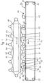
- the two upper rollers 21, 23 are mounted at approximately the same height on a machine frame, so that the conveyor belt between them, optionally supported by further rollers, extends approximately horizontally.
- a solid, elongated support 10 is mounted in the machine frame mentioned, which itself has a frame construction extending transversely to the plane of the figure can be.
- the carrier 10 is provided at its four corners above and below the plane of the figure with a sprocket, with an endless chain rotating around two sprockets.
- Each of the two chains, which are not shown, runs with their strands above and in the direction of the conveyor belt 20.
- equally spaced rods 41, 42, 43, 44, 45 of the same cross-section, which are indicated as circles, are fastened in the figures carried by the chains with them circulate around the carrier 10.
- at least one of the pinions is coupled to the drive of the machine.
- a cloth 46, 47, 48, 49 which extends over the length of the rods between the chains, is fastened in such a way that it loosely bridges the gap between adjacent rods.
- two adjacent rods, for example rods 41 and 42, with the cloth attached between them, for example cloth 46 each form a knitting chamber for one dough piece, that is to say approximately the knitting chamber 32 for dough piece 62.
- the carrier 10 is mounted at such a height above the run 26 that the active chambers 32, 34, 36, 38 located directly above the run 26 keep d at this small distance.
- Each knitting chamber has two opposing knitting cheeks 31, 33, which in the example shown are formed by the periphery of the rods which laterally delimit the knitting chamber and therefore have a convex shape in the figures.
- the knitted cheek can, as will be explained further below, be given a concave shape, which is particularly recommended for penetrating a dough piece.
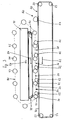
- the machine works as follows: At a depositing point 50 on the front part of the strand 26 in the conveying direction, dough pieces 62 are deposited one after the other on the driven conveyor belt, the strand 26 of which moves in the direction of the arrow 52. Together with the conveyor belt, the two chains and with them the knitting chambers attached to them are moved in such a way that the knitting chambers opposite your strand 26 are essentially in phase (except for the essential difference explained below). move with the strand 26 in direction 52. The dough piece 62 is thus gripped by the first active chamber from above and carried along. Accordingly, the dough pieces subsequently deposited at the depositing point 50 are taken along by the subsequent active chambers, whereby they remain on the strand 26.
- the knitting cheek 33 in the conveying direction has a pressing effect on the dough piece contained in the knitting chamber and transported (now slower relative to the knitting chamber movement) and thereby prepares one first fold in the dough piece.
- the front knitting cheek 31 of the same knitting chamber comes into pressing contact with the dough piece, which is now knitted from its front side, which also results in the fold in the dough piece.
- the dough piece Since the oscillating movement of the knitting chambers continues in this way over the entire length of the strand 26, which is covered by the knitting chambers, the dough piece is knitted accordingly several times on its conveying path, so that at the end of the strand 26, on which "its" knitting chamber from the Chains are forcibly lifted from the strand 26, fully worked and provided with a fine finish for further processing.
- the dough piece enclosed in a knitting channel cannot move upward out of the chamber, since the chamber cover 35, which is designed as a flexible cloth, prevents it from doing so.
- the dough piece 62 can thus avoid the active forces only by lateral elongation, for which the shape of each active chamber, which is elongated transversely to the paper plane, offers sufficient space.
- the dough piece 62 leaves the dough long knitting machine described as a long-knitted piece of dough with a clean finish.
- the ratio of the thickness to the length of the finished piece of dough can be influenced if the flexible chamber ceilings 35 are acted upon by a pressure beam common to all of the lower active chambers. Depending on its setting, this prevents the dough 62 from deflecting too far against the flexible chamber cover 35.
- the distance d can easily be changed in that the carrier is equipped with a lifting device which acts relative to the mounting of the conveyor belt 20 (which is not shown here). In this way, the intervention of the active cheeks in the dough piece is adapted to the consistency and the composition of the dough piece (wheat or rye base, etc.).
- each active chamber 32, 34, 36, 38 is in the form of an encircling belt 70 which moves at the same speed as the conveyor belt 20. Accordingly, the arrow 54 indicating the movement of the further band 70 is of the same length as the arrow 52.
- the chamber ceiling that is common to all of the active chambers 32 to 38 open toward the conveyor belt 20 is accordingly the lower run 72 of the further belt 70.
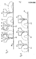
- Figures 4 and 5 show a special embodiment of the concave design of the active surfaces already explained above.
- the rods 41... 45 which are round in cross section in the preceding examples, have a rectangular profile here with a central extension that points toward the conveyor belt 20 and is concavely shaped on both sides and that merges into a strip 81.
- the front knuckle 92 consists of an upper concave wall section relative to the conveyor belt 20 and a lower rectilinear wall section 89 formed by the bar 81.
- the rear knuckle 94 consists of an upper concave section 91 and a lower rectilinear section 93, which is part of the inserted active bar 81 is.
- Figure 4 shows the formation of the end in three stages by the interaction of the front knuckle, whereby the dough piece 62 is first pushed together by the front knuckle 92 of the rod 82.
- the rear active cheek 94 then acts on the dough piece 62, as can be seen in FIG. 5, right partial image. If the feed speed of the carrier 10 then again becomes lower than the speed of the conveyor belt 20, the front active cheek 92 of the rod 82 acts on the front of the dough piece 62 according to the central partial image in FIG. 4, the end already forming clearly.
- the rear active cheek 94 acts on the dough piece 62 in accordance with the middle image in FIG. 5 to enlarge the conclusion which occurs during the subsequent movement phases of the carrier 10 in accordance with the left partial image from FIG. 4 and the left partial image from FIG desired deepened.
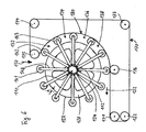
- the dough knitting machine has a cylindrical drum 120 which is coupled to a drive (not shown) and which can be rotated about an axis perpendicular to the plane of the drawing.
- the drum has a continuous coherent cylindrical surface 122.
- a wheel 110 is mounted on the two opposite end faces of the drum outside of the drum on a shaft 112, which has a plurality of radially extending arms, one of which is designated by 114.
- each arm 114 carries a rod extending at a distance d parallel to a surface line of the outer surface 122, two rods of which are designated by 141, 142.
- the rods 141, 142 correspond in their task and function to the rods 41 ... 45 from the embodiment of the invention explained above. Each of these rods 141 ; 142 therefore has knuckle cheeks for the dough piece not shown in this embodiment of the invention.
- the shaft of the wheel 110 is coupled to an active drive (not shown) and can be moved in an oscillating manner relative to the drum 120.
- an endless conveyor belt 1170 is guided over deflection rollers 171, 172, 173, 174, 175, 176 over part of the circumference of the drum 120, at least one of which is coupled to the drive of the drum 120.
- the conveyor belt 170 therefore has the same peripheral speed as the drum 120 over the peripheral section 180 surrounding the drum.
- the rods 141, 142 perform a movement which results from the superimposition of an oscillating movement over a same circumferential movement as the drum 120. In operation, therefore, the rods 141, 142 remain behind the movement of the drum surface 122 and the conveyor belt section 180 in order to then advance this movement again.
- active chambers 132, 134, 136, 138 are formed between two adjacent bars 141, 142 during their movement along the peripheral section 180.
- a dough piece is fed to the dough knitting machine from above along the arrow 150 and falls onto the outer surface 122 between two adjacent bars 141, 143.
- the dough piece is then carried along by the drum 120 and is worked through by the oscillating movement of the knitting cheeks to form a closure, as is the case with this has been explained in the above embodiments of the invention.
- the dough piece remains on the conveyor belt 170 and is discharged from the dough knitting machine at 152. It is understood that in the illustrated embodiment, drum 120 and section 180 of belt 170 are driven in a clockwise direction.
Landscapes
- Life Sciences & Earth Sciences (AREA)
- Engineering & Computer Science (AREA)
- Food Science & Technology (AREA)
- Manufacturing And Processing Devices For Dough (AREA)
- Bakery Products And Manufacturing Methods Therefor (AREA)
- Confectionery (AREA)
Priority Applications (1)
| Application Number | Priority Date | Filing Date | Title |
|---|---|---|---|
| AT86114079T ATE66570T1 (de) | 1985-10-10 | 1986-10-10 | Teigwirkmaschine. |
Applications Claiming Priority (2)
| Application Number | Priority Date | Filing Date | Title |
|---|---|---|---|
| DE3536127 | 1985-10-10 | ||
| DE19853536127 DE3536127A1 (de) | 1985-10-10 | 1985-10-10 | Teigwirkmaschine |
Publications (3)
| Publication Number | Publication Date |
|---|---|
| EP0218262A2 true EP0218262A2 (fr) | 1987-04-15 |
| EP0218262A3 EP0218262A3 (en) | 1988-06-15 |
| EP0218262B1 EP0218262B1 (fr) | 1991-08-28 |
Family
ID=6283228
Family Applications (1)
| Application Number | Title | Priority Date | Filing Date |
|---|---|---|---|
| EP86114079A Expired - Lifetime EP0218262B1 (fr) | 1985-10-10 | 1986-10-10 | Appareil pour travailler la pâte |
Country Status (3)
| Country | Link |
|---|---|
| EP (1) | EP0218262B1 (fr) |
| AT (1) | ATE66570T1 (fr) |
| DE (2) | DE3536127A1 (fr) |
Family Cites Families (5)
| Publication number | Priority date | Publication date | Assignee | Title |
|---|---|---|---|---|
| US3125039A (en) * | 1964-03-17 | Metering device for a dough kneading machine | ||
| DE548276C (de) * | 1926-07-09 | 1932-04-08 | Aribert Kremmling | Teigwirkmaschine mit endlosen Wirkbaendern |
| DE620395C (de) * | 1932-10-13 | 1935-10-21 | Otto Florian Dipl Ing | Wirkvorrichtung mit zwei die Teigstuecke zwischen sich bearbeitenden Gegenlagerflaechen, naepfen oder sonstigen Auflage- oder Anlagekoerpern |
| FR1256759A (fr) * | 1960-05-10 | 1961-03-24 | Werner & Pfleiderer | Dispositif pour le pétrissage en rond des pâtons |
| US3272153A (en) * | 1963-12-20 | 1966-09-13 | Topos Mondial Corp | Dough divider |
-
1985
- 1985-10-10 DE DE19853536127 patent/DE3536127A1/de not_active Withdrawn
-
1986
- 1986-10-10 EP EP86114079A patent/EP0218262B1/fr not_active Expired - Lifetime
- 1986-10-10 AT AT86114079T patent/ATE66570T1/de not_active IP Right Cessation
- 1986-10-10 DE DE8686114079T patent/DE3681108D1/de not_active Expired - Lifetime
Also Published As
| Publication number | Publication date |
|---|---|
| EP0218262A3 (en) | 1988-06-15 |
| DE3536127A1 (de) | 1987-04-16 |
| ATE66570T1 (de) | 1991-09-15 |
| DE3681108D1 (de) | 1991-10-02 |
| EP0218262B1 (fr) | 1991-08-28 |
Similar Documents
| Publication | Publication Date | Title |
|---|---|---|
| DE2803386C2 (fr) | ||
| DE102017112177B4 (de) | Schneideinheit sowie Schneidverfahren | |
| DE2703331C2 (de) | Vorrichtung zum kontinuierlichen Auswalken von Teig | |
| DD298732A5 (de) | Verfahren und vorrichtung fuer das ausrollen von teig | |
| EP0152053B1 (fr) | Elément de cardage | |
| DE3121030A1 (de) | "vorrichtung zum oeffnen von faserballen" | |
| DE3346895C2 (fr) | ||
| DE3444085C2 (de) | Vorrichtung zum Portionieren von Teig | |
| EP0218262B1 (fr) | Appareil pour travailler la pâte | |
| DE69324613T2 (de) | Rundwirkmaschine | |
| DE69816708T2 (de) | Vorrichtung zum Formen von Backwaren | |
| WO1996025046A1 (fr) | Dispositif permettant de produire des bandes de pate | |
| EP1111997A1 (fr) | Procede, composants et leur agencement pour le traitement de pate | |
| DE2108817C2 (de) | Vorrichtung zum Absetzen bzw. Umsetzen von Teigstücken | |
| AT407820B (de) | Vorrichtung zum rundwirken von teigstücken | |
| EP0391017B1 (fr) | Appareil pour mettre la pâte en boule | |
| EP1542540B1 (fr) | Procede d'aplatissement de denrees alimentaires, en particulier de morceaux de viande | |
| DE29723827U1 (de) | Teigbandformer | |
| DE19819636B4 (de) | Teigbearbeitungsmaschine | |
| DE3021329C2 (de) | Vorichtung zum Rundwirken von Teigstücken | |
| DE102004032992A1 (de) | Vorrichtung zum Umformen einer plastisch verformbaren Süßwarenmasse in ein Produkt | |
| DE3408859A1 (de) | Wurstfuellmaschine mit einer vorrichtung zur zipfelbildung und einer abschneideinrichtung fuer die wuerste | |
| EP4599681A1 (fr) | Dispositif d'alimentation d'une chaîne de saucisses à un dispositif de traitement ultérieur de la chaîne de saucisses | |
| DE3446032A1 (de) | Stapelvorrichtung fuer flaechige einzelerzeugnisse aus papier, zellstoffwatte o.dgl. | |
| DE2554175C3 (de) | Vorrichtung zum Bearbeiten von flachen, flexiblen Gegenständen, insbesondere zum Weichmachen von Leder |
Legal Events
| Date | Code | Title | Description |
|---|---|---|---|
| PUAI | Public reference made under article 153(3) epc to a published international application that has entered the european phase |
Free format text: ORIGINAL CODE: 0009012 |
|
| AK | Designated contracting states |
Kind code of ref document: A2 Designated state(s): AT DE FR |
|
| PUAL | Search report despatched |
Free format text: ORIGINAL CODE: 0009013 |
|
| RHK1 | Main classification (correction) |
Ipc: A21C 7/01 |
|
| AK | Designated contracting states |
Kind code of ref document: A3 Designated state(s): AT DE FR |
|
| 17P | Request for examination filed |
Effective date: 19881115 |
|
| 17Q | First examination report despatched |
Effective date: 19900703 |
|
| GRAA | (expected) grant |
Free format text: ORIGINAL CODE: 0009210 |
|
| AK | Designated contracting states |
Kind code of ref document: B1 Designated state(s): AT DE FR |
|
| REF | Corresponds to: |
Ref document number: 66570 Country of ref document: AT Date of ref document: 19910915 Kind code of ref document: T |
|
| REF | Corresponds to: |
Ref document number: 3681108 Country of ref document: DE Date of ref document: 19911002 |
|
| PGFP | Annual fee paid to national office [announced via postgrant information from national office to epo] |
Ref country code: AT Payment date: 19911010 Year of fee payment: 6 |
|
| PGFP | Annual fee paid to national office [announced via postgrant information from national office to epo] |
Ref country code: FR Payment date: 19911030 Year of fee payment: 6 |
|
| ET | Fr: translation filed | ||
| PGFP | Annual fee paid to national office [announced via postgrant information from national office to epo] |
Ref country code: DE Payment date: 19911218 Year of fee payment: 6 |
|
| PLBE | No opposition filed within time limit |
Free format text: ORIGINAL CODE: 0009261 |
|
| STAA | Information on the status of an ep patent application or granted ep patent |
Free format text: STATUS: NO OPPOSITION FILED WITHIN TIME LIMIT |
|
| 26N | No opposition filed | ||
| PG25 | Lapsed in a contracting state [announced via postgrant information from national office to epo] |
Ref country code: AT Effective date: 19921010 |
|
| PG25 | Lapsed in a contracting state [announced via postgrant information from national office to epo] |
Ref country code: FR Effective date: 19930630 |
|
| PG25 | Lapsed in a contracting state [announced via postgrant information from national office to epo] |
Ref country code: DE Effective date: 19930701 |
|
| REG | Reference to a national code |
Ref country code: FR Ref legal event code: ST |