EP0218237A1 - Running rail - Google Patents
Running rail Download PDFInfo
- Publication number
- EP0218237A1 EP0218237A1 EP86113896A EP86113896A EP0218237A1 EP 0218237 A1 EP0218237 A1 EP 0218237A1 EP 86113896 A EP86113896 A EP 86113896A EP 86113896 A EP86113896 A EP 86113896A EP 0218237 A1 EP0218237 A1 EP 0218237A1
- Authority
- EP
- European Patent Office
- Prior art keywords
- running
- track
- profile
- running rail
- rail
- Prior art date
- Legal status (The legal status is an assumption and is not a legal conclusion. Google has not performed a legal analysis and makes no representation as to the accuracy of the status listed.)
- Granted
Links
Images


Classifications
-
- B—PERFORMING OPERATIONS; TRANSPORTING
- B65—CONVEYING; PACKING; STORING; HANDLING THIN OR FILAMENTARY MATERIAL
- B65G—TRANSPORT OR STORAGE DEVICES, e.g. CONVEYORS FOR LOADING OR TIPPING, SHOP CONVEYOR SYSTEMS OR PNEUMATIC TUBE CONVEYORS
- B65G21/00—Supporting or protective framework or housings for endless load-carriers or traction elements of belt or chain conveyors
- B65G21/20—Means incorporated in, or attached to, framework or housings for guiding load-carriers, traction elements or loads supported on moving surfaces
- B65G21/22—Rails or the like engaging sliding elements or rollers attached to load-carriers or traction elements
-
- E—FIXED CONSTRUCTIONS
- E01—CONSTRUCTION OF ROADS, RAILWAYS, OR BRIDGES
- E01B—PERMANENT WAY; PERMANENT-WAY TOOLS; MACHINES FOR MAKING RAILWAYS OF ALL KINDS
- E01B25/00—Tracks for special kinds of railways
- E01B25/22—Tracks for railways with the vehicle suspended from rigid supporting rails
- E01B25/24—Supporting rails; Auxiliary balancing rails; Supports or connections for rails
Definitions
- the invention relates to a running rail of the type specified in the preamble of claim 1.
- a known track is a steel angle profile with an underside open between the legs, which is welded in the conveyor section profile through the support web forming web sections with a continuous steel profile, for example, a round tube.
- the production of a conveyor section of a suspended conveyor is complex because it is made to measure from many individual parts, so to speak.
- the running track can only be driven on with the center-hung pairs of rollers.
- the open underside of the running rail allows the pair of rollers to be unhooked; on the other hand, it requires the attachment of additional components to prevent unhooking in the unblocking sections of the conveyor line for safety reasons.
- the open angle profile of the running rail creates a high torque and a high material load or material accumulation on the top of the running rail.
- the weight of the running rail and also a unit length of the conveyor line is high due to the design. Due to the horizontal asymmetry of the running track, up and down arches have to be made differently. The welding delay during the manufacture of a conveyor line causes large manufacturing tolerances. The exact vertical position of the plane of symmetry of the running rail cannot be guaranteed after assembly. The high weight of the running rail and the conveyor line result in high transport costs. By due to the material of the running track, expensive corrosion protection is required. In connection or joint areas of a conveyor line, different connection elements are required for the holding web and the running rail.
- the invention has for its object to provide a running rail of the type mentioned, which can be used universally for different purposes and is more stable, load-bearing and lighter than the known one.
- the crossbar With the crossbar, a hollow profile is created, which ensures a higher load capacity of the running rail so that the running rail can be formed more easily than the known one.
- the crossbar leads with the legs and the cavity to a favorable moment of inertia and resistance of the running rail.
- the crossbar also ensures a constant distance between the legs, which favors the formation of up and down arches.
- the load on the running rail is reduced in the upper connection area of the legs, because the crossbar underneath also has a laterally stiffening effect.
- the feature of claim 3 is also important because it creates a heavy-duty connection between the retaining web and the running rail and also always ensures that the plane of symmetry of the running rail is exactly vertical.
- the molded support web also saves the previously laborious connection work of the running rail with the support web sections, because the molded support web is to be connected directly to the support profile.
- the embodiment of claim 4 is also important, because in this way the resilience of the conveyor section profile created in this way can be precisely predetermined by the size and number of openings, and the weight per unit length. Due to the dimensioning of the distance between the edge of the opening and the underside of the crosspiece, the location of certain openings leads from the outset to areas of the conveyor path in which the rollers can be removed. The width of the roller conveyor or the leg can be larger than the width of the unhooking gap.
- the feature of claim 5 is also favorable because the supporting web increases the structural strength of the running rail and nevertheless does not impair the desired unhooking of the pair of running rollers.
- the optionally open underside of the running rail which extends as far as the crossbar, does not need to be used when the pair of rollers is removed, which simplifies the removal. It is even possible that the crossbar connects the free leg ends directly to one another.
- the longitudinal grooves do not impair the structural strength and resilience of the running rail; however, they permit the attachment and securing of additional devices. In addition, they produce any desired elasticity in the vertical direction in the web.
- the undercut groove within the cross section of the track is intended for secondary tasks, e.g. for attaching or inserting additional devices or holding pieces which can then be displaced in the longitudinal direction of the running rail and can be fixed as desired.
- the feature of claim 11 is also expedient, since movable or inserted parts are neatly supported and guided on the guide or support surfaces.
- roller tracks can be accommodated in the longitudinal grooves, conductor lines or supply cables, or also plastic supports for the roller tracks, which are then additionally suspended at the bottom of the groove in the running rail.
- the surfaces on the extensions of the leg ends can have parts of roller tracks of differently designed or suspended roller types when the running rail is installed differently len be. Rollers can also run on the contact surfaces on the underside of the crossbar if the track is installed in a different position. A running track with a complex profile is created, so to speak, which can be used for various applications that arise with the design of a conveyor line.
- the running track is integrated into the conveyor section profile from the start, from which the conveyor section can be assembled in a modular manner.
- This profile there is no need to connect the running rail to the support profile and the need for continuous customization.
- the profiles are designed to be inexpensive in terms of assembly technology and are easy to couple and support.
- the crossbar of the running rail or the support profile could also be omitted for certain applications.
- the running track profile can be used in at least two different installation positions, the running rollers each running on the profile part below. Depending on the installation position, there is then a display area or a display blocking area.
- the embodiment of claim 14 is expedient because the longitudinal reinforcement accommodated in the cavity increases the load-bearing capacity of the running rail or the route profile.
- reinforcement strips or bands can be drawn into the cavity and, if necessary, cast or foamed.
- the additional rail which is mirror image is attached either to the running rail or to the support profile, using the shape of the profiles, the load capacity of the conveyor section can be increased either continuously or only in sections.
- the additional rail also has the profile of the running rail.
- An embodiment as it appears from claim 16 is also favorable.
- the running profiles can be easily, e.g. Fasten in the groove on the underside.
- center-hung and side-hung roller brackets can be used on the same overhead conveyor line, which run directly one behind the other.
- track profile can be designed from the outset to be suitable for a plurality of roller bracket systems, it being expedient that the tracks of the compatible systems do not impede the roller bracket of the respective other system.
- Another multi-system track can also be used without a support bar and support profile, e.g. be made in one piece.
- the basic cross-sectional shape is retained and only expanded with regard to the additional task.
- the crossbar within the cross-section is not absolutely necessary.
- the locking part can be retrofitted or removed, depending on the existing requirements.
- the shape of the running rail according to the modifiable modular principle also allows simple subsequent changes to the system, for example for adaptation to changing operating requirements .
- the shape of the running rail and its integration into the running track profile is expediently used in accordance with claim 20 in order to attach the fastening means, the suspension or support of a conveyor track.
- the loads occurring when driving on the conveyor line are transmitted here favorably from the longitudinal grooves via the fastening means to the support of the conveyor line.
- the coupling of abutting conveyor sections is also simplified because e.g. pin-shaped, coupling elements only need to be inserted into the longitudinal grooves and then automatically ensure that the rails do not move relative to each other.
- claim 21 is also important because holders arranged in the longitudinal grooves fix the additional devices in a particularly simple manner.
- the shape of the running rail and also of the running track profile has an advantage, as can be seen from claim 22.
- the flow and return are attached in the grooves of the profiles without the need for expensive fastening or adjustment means.
- supports or wall rails are even created from the basic profile for mounting the conveyor line.
- claim 26 is also expedient because these holding pieces can also be used to create angles, curves and gradients that deviate from 90 °.
- the feature of claim 27 is also important because light metal or light metal alloys can be extruded easily and inexpensively with the desired cross-sectional profile and practically infinitely, the extruded profile being very precise in shape, insensitive to corrosion, lightweight, wear-resistant and visually appealing.
- the specific lower resilience of the material compared to steel is more than compensated for by the chosen cross-section of the running track.
- claim 28 As an alternative to this, an embodiment according to claim 28 is also conceivable, the weight saving compared to structures welded from steel and the simplified production of the conveyor track again being significant.
- claim 29 is also important, because plastic running tracks or running track profiles can also be used for lighter purposes. In the case of plastic production in particular, it can be important to reinforce the cavity that the crossbar delimits with the legs, or the legs themselves. Plastic leads to a quiet running noise of the rollers. Curves are particularly easy to form because of their elasticity.
- rollers 54 and 55 of a pair of rollers 53 which are held in a bracket 57 connecting their inclined axes 56 to each other, on which transport means (not shown) hang.
- the bracket 57 has below the running rail 1 a recess which allows the lifting and unhooking of the rollers 54, 55.
- the running rail 1 is laterally symmetrical with respect to a vertical plane of symmetry S.
- the legs 2 connects the legs 2 to a cross bar 4.
- the legs 2 end at a transverse distance from the plane of symmetry S and are connected to one another by a web 5 which runs approximately parallel to the cross bar 4 .
- the transverse web 4 delimits a cavity 6 with the inner sides of the legs 2 and the web 5, in which longitudinal reinforcements 8, for example, are embedded or cast in, if necessary.
- the free cavity 6 can be used to accommodate supply lines or the like.
- projections 7 are formed, which have inclined guide surfaces 9 and 4 parallel guide surfaces 10 to the crosspiece.
- the angle which the guide surfaces 9 enclose with the plane of symmetry S is 60 °, while the angle between the roller tracks 3 and the plane of symmetry S is approximately 45 °.
- the projections 7 delimit with the crossbar 4 a dovetail groove 12 which is open towards the underside of the running rail 1 and which is delimited on the outside by undercut surfaces 11.
- Guide surfaces 13 adjacent to the surfaces 11 can be formed on the underside of the crossbar 4.
- the web 5 has a flat upper surface 14 and is integrally united with a supporting web 15 which runs upwards in the plane of symmetry S.
- a supporting web 15 which runs upwards in the plane of symmetry S.
- longitudinal grooves 18 are formed in the web 15, which are expediently undercut.
- the support web 15 contains openings 16, the lower opening edge 17 being below the imaginary intersection of the raceways 3 in the plane of symmetry S.
- the running rail 1 is primarily intended for the operating position shown in FIGS. 1 and 2, in which the supporting web 15 is vertical.
- the rollers 54, 55 of the respective bracket 57 can also run simultaneously on the raceways 3 of the running rail and the support profile 21.
- the neutral fiber of the cross section of the running rail 1 used alone lies approximately in the transverse web 4 or directly on its surface, while in the running section profile 20 it lies approximately in the longitudinal central axis in the supporting web 15.
- the support profile 21 is a mirror image of the running rail 1 and has approximately the same cross section as this.
- the actual position of the neutral fiber depends, among other things. according to the asymmetry of the openings 16 in the supporting web 15.
- the upper opening edge 17 'of each opening 16 is further away from the support profile 21 than the lower opening edge 16 from the running rail 1.
- the openings 16 can be elongated holes or also circular.
- the supporting web 15 runs over the length of the running track profile 20.
- the running section profile can be inserted either with the supporting section 21 at the top or with the running rail 1 at the top, in which case the supporting section 21 then forms the actual running track.
- the selected installation position depends, among other things. depends on whether the asymmetry of the openings 16 is intended to create a detachment or a detachment area, as will be explained later.
- Plastic running layers could be applied to the raceways 3 of the running rail 1 of FIG. 1, which layers are then expediently hooked into the longitudinal grooves 18 and the dovetail groove 12 in a form-fitting manner.
- the running track profile 20 according to FIG. 2 can be provided by holding pieces 73, e.g., in the dovetail groove 12 of the supporting profile 21 or in the (other installation position) of the running rail 1.
- Fig. 14 on a support, e.g. 13, or also with a fastening element encompassing the legs of the support profile 21 on the outside.
- holding elements 40, 42 (FIG. 7) can also engage in the longitudinal grooves 18.
- the support profile 21 is combined with a rail 22, e.g. by means of connecting pieces 58 inserted into the dovetail grooves 12 or by means of fastening screws in the plane of symmetry S, as a result of which the rigidity and resilience of the running track profile 20 are increased.
- the profile of the rail 22 corresponds approximately to that of the running rail 1 or the support profile 21.
- the profile of the rail 22 does not have a support web 15 here, but rather a dovetail groove 23 open at the top for hanging parts and a flat web 5 'which is closer to the cross web 4 than the web 5 and the crossbar 4 in the running rail according to FIG. 1.
- the rail 22 is attached to the running rail 1, e.g. by fastening elements 25 in the plane of symmetry, so that a cavity 24 remains free.
- the rail 22 is supported on the surfaces 10 of the projections 7 of the running rail 1.
- the roller bracket 57 can be used despite the rail 22.
- the running rail 1 according to FIG. 4a holds in the dovetail groove 12 a single-wing running profile 27 which, together with the running track 3, has a running profile with a running track 28 for a roller system with upright roller 32 shows.
- This can be the roller 32 of a side-hung roller bracket 57. It is important that here, one after the other and at the same time the roller pairs 53 with their roller brackets 57 which laterally contactlessly overlap the raceway 28 and the rollers 32 with their roller brackets 57 which hang down laterally can be used.
- Coupling or centering pins 26 can be inserted into the longitudinal grooves 18 in butt joints of running track profiles (FIG. 4a).
- a two-winged running profile 27 'with two raceways 28 is used, so that upright standing rollers 32 can run with their roller bracket 57 on both sides of the running rail 1.
- the pairs of rollers 3 according to FIG. 5a can also be used at the same time.
- the running profiles 27 ′′, 27 can also be integrated in one piece from the outset into the running rail 1 if operation with different roller systems is fundamentally desired.
- FIG. 5a shows how the rollers 54 and 55 of the pair of rollers 53 are supported on the running rail 1.
- FIG. 1 the distance between the underside of the crosspiece 4 and the lower opening 17 is smaller than the removal gap width A.
- a release lock in the form of a locking part 29 is provided, which is inserted into the longitudinal groove 18 of the running rail 1 and fixed therein. It has an upstanding edge which prevents the pair of rollers 53 from being detached. To unhook a correspondingly shaped recess is provided below the rail 1 in the bracket 57.
- a release lock in the form of a block 30 is provided, which is inserted into the dovetail groove 12 where a removal of the pair of rollers is not desired for safety reasons.
- the block 30 protrudes so far below the underside of the running rail 1 that the pair of rollers 53 cannot be pulled sideways.
- the additional running profile 27 'of FIG. 4b is designed as a shaped piece 31, which also forms a raised section 34 as a locking device for another roller system with vertically standing rollers 32, which runs on the raceways 33 and 3.
- the dash-dotted bracket 57 which hangs on the rollers 32, can not be raised so far in the region of the raised portion 34 that the rollers 32 could be lifted over the raceways 33.
- Section 34 also locks if only one side-suspended roller 32 is provided.
- an arbitrarily actuated lockout in the form of a slide 35 with an actuating extension 36 is attached to the supporting web 15 so that it can be lifted out of the longitudinal groove 18 and moved upward until the pair of rollers 53 has been removed. If, on the other hand, the release lock is seated in the longitudinal groove 18, it is no longer possible to unhook through the opening 16 in this area.
- 5a, 5b, 5c and 6a and 6b can practically be attached anywhere on the running rail 1 or the running track profile 20.
- the running track profile 20 is designed with a higher supporting web height, a holding plate 44 being inserted and screwed on one side of the supporting web 15 into the longitudinal grooves 18 of the running rail 1 and the supporting profile 21, the receptacles 45 for power cables or the like. holds on.
- These can, for example, also be grinding and contact devices for an electrically operated overhead conveyor.
- FIG. 9 shows a support 51 which can be used to support a suspended conveyor line or to create a support frame 70 (FIG. 13) and consists of rails 22 as used in accordance with FIGS. 3a and 3b.
- the rails 22 are offset by 120 0 with each other and screwed together by fasteners 52, wherein the surfaces 9 abut each other. 1 could also be connected to such supports. Two or four rails could also be connected. Flat wall rails could also be formed in this way.
- the running track profile 20 could also be used as such supports, ie, on the basis of the cross section of the running rail 1 according to FIG. 1 or that of the running track profile 20 according to FIG. 2, additional components can be created in a modular manner, which are used for mounting or building a conveyor track will.
- the running track profile 20 is intended for a round link chain conveyor, a chain return 46 being fastened in the dovetail groove 12 of the supporting profile 21 and a chain forward run 47 being fastened in the dovetail groove 12 of the running rail 1.
- FIG. 11 shows a running track profile 20 'of an inclined conveyor track in which a chain return 50 is arranged in the dovetail groove 12 of the supporting profile 21 and a chain feed 48 is arranged in the dovetail groove 12 of the running rail 1, in which a chain 49 is guided for pairs of running rollers running on the running rail 1 becomes.
- FIG. 12a and 12b show an operating position of the running track profile 20 rotated by 90 ° with respect to the previously described operating positions, the running track profile 20 being used for a container transport system 63 or 67.
- the lying Running track profile 20 with a holding part introduced into the grooves 18 and fixed there is held on an underlying support.
- the rollers 54, 55, which are held in the roller bracket 57, run on the overhead, V-shaped tracks 3 of the running rail and the support profile of the track section 20.
- the load resting on the roller bracket 57 is indicated by 66.
- the lying running track profile 20 is suspended via a holding part 69 in the grooves 18 and a center suspension 68, on both sides of which the rollers 54 and 55 of the roller bracket 20 running around the outside of the running track profile run downward.
- the load or the container (not shown) hangs on the roller bracket 57.
- FIG. 13 shows a part of a conveyor line, the conveyor line being formed in a support frame or support grate 70 with two parallel parallel driveways 71, 72, each of which consists of butted runway profiles 20.
- the scaffolding is also composed of sections of the running track profile 20, namely the upper cross members, which are supported on the supports 51 on the ground. If necessary, the cross beams from the running track profiles 20 can also be fastened with ceiling suspensions 77.
- the running track profiles 20 of the two driveways 71, 72 are fastened to the underside of the cross supports, for example with holding pieces 73 shown enlarged and in perspective in FIG. 14, which in the dovetail grooves 12 (not shown in FIG. 13) on the mutually facing running rails 1 and Support profiles 21 are used.
- each running track profile 20 is fastened with its supporting web 21 to the cross member of the scaffold 70, so that the running rail 1 lies below.
- the openings 16 lie on the barrel slide ne 1 so close that it is possible to unhook the rollers in this area.
- the running track profiles 20 are rotated by 180 ° and fastened to the cross members with the running rails 1, so that the supporting profiles 21 lie at the bottom, on which the pairs of rollers run. Since, due to the asymmetrical position of the openings 16, the distance between the lower opening edge and the support profile 21 is too large for an unhinging, there is an unblocking area in which the pairs of rollers cannot be unhinged.
- sliding block parts 74, 75 consists of two cross-shaped and interconnected sliding block parts 74, 75, the sliding block parts 74, 75 being connected either in one piece or releasably by fastening means 76, so that in the latter case the relative position of the sliding block parts 74, 75 is adjustable and these are also in the dovetail grooves 12 from the outset and can only be connected during assembly, zRreit through the legs of the support profile tools.
- the running rail 1 and the supporting web 15 with the supporting profile 25 can not only be extruded from light metal or light metal alloys, but also sheet metal pressing and welding or a plastic design, for example glass fiber reinforced plastic, is conceivable.
- a composite construction made of different materials would also be possible.
- Common to all design variants is a relatively low weight per unit length, a high load capacity and high torsional and bending strength.
- the material pairing with the roller used in each case can be simply optimize for wear and running noise. With the profile concept created, different attachments and assembly elements can be easily connected.
- the profile of the running rail 1 permits the problem-free formation of upward and downward sections, as well as their transitions into horizontal travel sections and the formation of left or right curves.
- Check-out areas can be provided just as easily as check-out areas.
- the conveyor line can be adjusted to the side, center and bottom suspension, as the profile shape is designed with regard to possible additional requirements.
- a conveyor line can also be adapted to other roller systems using the running rail 1 or the running route profile of the previous FIG. With additional devices or even from the start, even so that several roller systems can be used simultaneously.
- Container transport systems with a horizontal arrangement of the running track profile, ie rotated by 90 °, are also possible applications.
- the running track profile can also be used well for monorail overhead conveyors because it is easy to attach conductor lines to the supporting web or the supporting profile. Since the running rail 1 has differently inclined surfaces which merge into one another, there is the possibility of using roller or operating means with different angles of attack of the rollers alternately or simultaneously.
- new drive concepts can be integrated into the profile of the route section, for example chain conveyors and the like. Resources can also run on the support profile if the conveyor route is suspended on the side or in the middle. is. There is no need to weld the sections because the connection is just as easy to carry.
- a post-treatment or surface refinement is unnecessary as a base material for light metal or light metal alloy. However, it can be anodized from decorati ven reasons and for surface finishing are provided. In the same way, however, individual coloring is possible to emphasize differently important sections of the route.
Abstract
Description
Die Erfindung betrifft eine Laufschiene der im Gattungsbegriff des Patentanspruchs 1 angegebenen Art.The invention relates to a running rail of the type specified in the preamble of
Eine bekannte Laufschiene ist ein Stahl-Winkelprofil mit zwischen den Schenkeln offener Unterseite,das im Förderstreckenprofil durch den Tragsteg bildende Stegabschnitte mit einem, z.B. als Rundrohr ausgebildeten, Endlos-Stahlprofil verschweißt ist. Die Herstellung einer Förderstrekke einer Hängeförderbahn ist aufwendig, da sie sozusagen aus vielen Einzelteilen maßgefertigt wird. Die Laufschiene kann nur mit mittenabgehängten Laüfrollenpaaren befahren werden. Die offene Unterseite der Laufschiene gestattet zwar das Aushängen des Laufrollenpaares; andererseits bedingt sie das Anbringen zusätzlicher Bauteile, um sicherheitsbedingt in Aushängesperr-Abschnitten der Förderstrecke das Aushängen zu verhindern. Durch das offene Winkelprofil der Laufschiene entsteht ein großes Drehmoment und eine hohe Materialbelastung bzw. Materialanhäufung an der Oberseite der Laufschiene. Das Gewicht der Laufschiene und auch einer Längeneinheit der Förderstrecke ist konstruktionsbedingt hoch. Aufgrund der horizontalen Asymmetrie der Laufschiene müssen Auf- und Abwärtsbögen unterschiedlich gefertigt werden. Der Schweißverzug beim Herstellen einer Förderstrecke bewirkt große Fertigungstoleranzen. Auch kann die exakt senkrechte Lage der Symmetrieebene der Laufschiene nach der Montage nicht gewährleistet werden. Durch das hohe Gewicht der Laufschiene und der Förderstrecke entstehen hohe Transportkosten. Durch das Material der Laufschiene bedingt ist ein teuerer Korrosionsschutz erforderlich. In Verbindungs- oder Stoßbereichen einer Förderstrecke sind unterschiedliche Verbindungselemente für den Haltesteg und die Laufschiene erforderlich.A known track is a steel angle profile with an underside open between the legs, which is welded in the conveyor section profile through the support web forming web sections with a continuous steel profile, for example, a round tube. The production of a conveyor section of a suspended conveyor is complex because it is made to measure from many individual parts, so to speak. The running track can only be driven on with the center-hung pairs of rollers. The open underside of the running rail allows the pair of rollers to be unhooked; on the other hand, it requires the attachment of additional components to prevent unhooking in the unblocking sections of the conveyor line for safety reasons. The open angle profile of the running rail creates a high torque and a high material load or material accumulation on the top of the running rail. The weight of the running rail and also a unit length of the conveyor line is high due to the design. Due to the horizontal asymmetry of the running track, up and down arches have to be made differently. The welding delay during the manufacture of a conveyor line causes large manufacturing tolerances. The exact vertical position of the plane of symmetry of the running rail cannot be guaranteed after assembly. The high weight of the running rail and the conveyor line result in high transport costs. By due to the material of the running track, expensive corrosion protection is required. In connection or joint areas of a conveyor line, different connection elements are required for the holding web and the running rail.
Der Erfindung liegt die Aufgabe zugrunde eine Laufschiene der eingangs genannten Art zu schaffen, die für unterschiedliche Einsatzzwecke universell verwendbar und dabei stabiler, tragfähiger und leichter ist, als die bekannte.The invention has for its object to provide a running rail of the type mentioned, which can be used universally for different purposes and is more stable, load-bearing and lighter than the known one.
Die Aufgabe wird erfindungsgemäß durch die im kennzeichnenden Teil des Patentanspruchs 1 angegebenen Merkmale gelöst.The object is achieved by the features specified in the characterizing part of
Mit dem Quersteg wird ein Hohlprofil geschaffen, das eine höhere Belastbarkeit der Laufschiene gewährleistete so daß die Laufschiene leichter ausgebildet werden kann, als die bekannte. Der Quersteg führt mit den Schenkeln und dem Hohlraum zu einem günstigen Trägheits- und Widerstandsmoment der Laufschiene. Der Quersteg sichert auch einen gleichbleibenden Abstand der Schenkel, was die Ausbildung von Auf- und Abwärtsbögen begünstigt. Die Belastung der Laufschiene ist im oberen Verbindungsbereich der Schenkel verringert, weil sich der darunterliegende Quersteg zusätzlich seitlich versteifend auswirkt.With the crossbar, a hollow profile is created, which ensures a higher load capacity of the running rail so that the running rail can be formed more easily than the known one. The crossbar leads with the legs and the cavity to a favorable moment of inertia and resistance of the running rail. The crossbar also ensures a constant distance between the legs, which favors the formation of up and down arches. The load on the running rail is reduced in the upper connection area of the legs, because the crossbar underneath also has a laterally stiffening effect.
Eine zweckmäßige Ausführungsform geht aus Anspruch 2 hervor. Bei dieser Ausbildung wird trotz hoher Belastbarkeit eine verhältnismäßig niedrige Schienenhöhe erreicht. Eine Materialanhäufung im Verbindungsbereich der Schenkel ist vermieden. Die Lage der neutralen Faser innerhalb des Querschnittes der Laufschiene läßt sich in wünschenswerter Weise genau vorherbestimmen bzw. in eine für die Belastung günstige Position legen.An expedient embodiment emerges from
Wichtig ist ferner das Merkmal von Anspruch 3, weil damit eine hochbelastbare Verbindung zwischen dem Haltesteg und der Laufschiene geschaffen und auch stets gewährleistet ist, daß die Symmetrieebene der Laufschiene genau senkrecht steht. Der angeformte Tragsteg erspart auch die bisher mühseligen Verbindungsarbeiten der Laufschiene mit den Tragstegabschnitten, weil der angeformte Tragsteg mit dem Tragprofil unmittelbar zu verbinden ist.The feature of
Wichtig ist auch die Ausführungsform von Anspruch 4, weil auf diese Weise die Belastbarkeit des so geschaffenen Förderstreckenprofils durch die Größe und Anzahl der Durchbrechungen, sowie das Gewicht pro Längeneinheit genau vorherbestimmbar sind. Die Lage bestimmter Durchbrechungen führt wegen der Abstandsbemessung zwischen dem Durchbrechungsrand und der Unterseite des Querstegs von vornherein zu Bereichen der Förderstrecke, in denen die Laufrollen aushängbar sind. Die Breite der Laufrollenbahnen bzw. der Schenkel kann dabei durchaus größer sein als die Aushängespalt-Weite.The embodiment of
Günstig ist dabei auch das Merkmal von Anspruch 5, weil der Tragsteg die Gestaltfestigkeit der Laufschiene erhöht und trotzdem das gewünschte Aushängen des Laufrollenpaares nicht beeinträchtigt. Bei der hierbei geringen Laufschienenhöhe braucht die gegebenenfalls offene Unterseite der Laufschiene, die sich bis zum Quersteg erstreckt, beim Aushängen des Laufrollenpaares gar nicht genutzt zu werden, was das Aushängen vereinfacht. Es ist sogar möglich, daß der Quersteg die freien Schenkelenden unmittelbar miteinander verbindet.The feature of
In einem Aushängesperrabschnitt ist gemäß Anspruch 6 von vornherein ohne zusätzliche Maßnahmen kein Aushängen des Laufrollenpaares mehr möglich.Unhooking the pair of rollers is no longer possible from the outset in a lockout section without additional measures.
Ein weiterer, wichtiger Gedanke ist in Anspruch 7 enthalten. Die Längsnuten beeinträchtigen die Gestaltfestigkeit und Belastbarkeit der Laufschiene nicht; sie gestatten jedoch das Anbringen und Lagesichern von Zusatzeinrichtungen. Dazu kommt, daß sie jm Steg eine gegebenenfalls gewünschte Elastizität in Hochrichtung erzeugen.Another important thought is included in
Ein weiterer, zweckmäßiger Gedanke ist in Anspruch 8 enthalten. Die Vorsprünge führen zu Materialanhäufungen in diesem Bereich des Querschnittes, wo sie einen günstigen Einfluß auf die Belastbarkeit und das Trägheits- und das Widerstandsmoment der Laufschiene haben.Another useful idea is included in
Günstig ist ferner der Gedanke von Anspruch 9, weil Belastungen von an den Vorsprüngen angreifenden Abhängungen oder Abstützungen sich großflächig verteilen.The idea of
Ein weiterer, wichtiger Gedanke ist in Anspruch 10 enthalten. Die hinterschnittene Nut innerhalb des Querschnitts der Laufschiene ist für sekundäre Aufgaben bestimmt, z.B. zum An- oder Einbringen von Zusatzeinrichtungen oder Haltestücken, die dann in Längsrichtung der Laufschiene verschiebbar und beliebig festlegbar sind.Another important thought is included in
Zweckmäßig ist auch das Merkmal von Anspruch 11, da an den Führungs- oder Auflageflächen bewegliche oder eingeschobene Teile sauber abgestützt und geführt werden.The feature of
Bei den vorgenannten Ausführungsformen ist es ferner günstig, daß, z.B. in den Längsnuten, Schleifleitungen oder Versorgungskabel untergebracht werden können, oder auch Kunststoffauflagen für die Rollenlaufbahnen, die dann unten in die Nut der Laufschiene zusätzlich eingehängt werden. Die Flächen an den Fortsätzen der Schenkelenden können bei anderer Einbaulage der Laufschiene Teile von Rollenlaufbahnen anders gestalteter oder abgehängter Laufrollen sein. Auch an den Auflageflächen an der Unterseite des Quersteges können bei anderer Einbaulage der Laufschiene Rollen laufen. Es wird sozusagen eine Laufschiene mit komplexem Profil geschaffen, das den Einsatz der Laufschiene für verschiedene und mit der Konzeption einer Förderstrecke entstehende Anwendungen brauchbar ist.In the aforementioned embodiments, it is also advantageous that, for example, can be accommodated in the longitudinal grooves, conductor lines or supply cables, or also plastic supports for the roller tracks, which are then additionally suspended at the bottom of the groove in the running rail. The surfaces on the extensions of the leg ends can have parts of roller tracks of differently designed or suspended roller types when the running rail is installed differently len be. Rollers can also run on the contact surfaces on the underside of the crossbar if the track is installed in a different position. A running track with a complex profile is created, so to speak, which can be used for various applications that arise with the design of a conveyor line.
Eine weitere Ausführungsform mit eigenständiger Bedeutung geht aus Anspruch 12 hervor. Die Laufschiene ist von vornherein in das Förderstreckenprofil integriert, aus dem die Förderstrecke baukastenartig zusammensetzbar ist. Es entfällt bei Verwendung dieses Profils das Verbinden der Laufschiene mit dem Tragprofil und die Notwendigkeit einer fortlaufenden Maßanfertigung. Die Profile sind montagetechnisch günstig konzipiert und einfach zu koppeln und abzustützen. Bei dieser Ausführungsform könnte für bestimmte Anwendungen auch der Quersteg der Laufschiene bzw. des Tragprofils weggelassen werden.A further embodiment with independent meaning emerges from
Ein weiterer, für sich alleine gesehen wichtiger Gedanke geht aus Anspruch 13 hervor. Im Sinne des Baukastenprinzips der Erfindung läßt sich das Laufstreckenprofil in zumindest zwei verschiedenen Einbaulagen verwenden, wobei die Laufrollen jeweils auf dem untenliegenden Profilteil laufen. Je nach Einbaulage liegt dann ein Aushängebereich oder ein Aushänge-Sperrbereich vor.Another thought, which is important in itself, emerges from
Weiterhin ist die Ausführungsform von Anspruch 14 zweckmäßig, weil die im.Hohlraum untergebrachte Längsarmierung die Belastbarkeit der Laufschiene oder des Streckenprofils erhöht. Es können dazu in den Hohlraum Armierungsstreifen oder Bänder eingezogen und gegebenenfalls eingegossen oder eingeschäumt sein.Furthermore, the embodiment of claim 14 is expedient because the longitudinal reinforcement accommodated in the cavity increases the load-bearing capacity of the running rail or the route profile. For this purpose, reinforcement strips or bands can be drawn into the cavity and, if necessary, cast or foamed.
Ein weiterer, wichtiger Gedanke geht aus Anspruch 15 hervor. Mit der zusätzlichen Schiene, die spiegelbildlich entweder an der Laufschiene oder am Tragprofil angebracht wird, und zwar unter Nutzung der Formgebung der Profile, läßt sich die Belastbarkeit des Förderstreckenprofils entweder durchgehend oder auch nur abschnittsweise erhöhen. Im Sinne des Baukastenprinzips hat auch die zusätzliche Schiene das Profil der Laufschiene.Another important idea arises from
Günstig ist ferner eine Ausführung wie sie aus Anspruch 16 hervorgeht. Mit dem Laufschienenprofil besteht hierbei die Möglichkeit, zusätzlich und gleichzeitig auch andere Laufrollensysteme einsetzen zu können. Die Laufprofile lassen sich einfach, z.B. in der unterseitigen Nut befestigen. Auf diese Weise können, z.B.,mittenabgehängte und seitenabgehängte Rollenbügel auf derselben Hängeförderstrecke eingesetzt werden, die unmittelbar hintereinander laufen.An embodiment as it appears from
Ein weiterer, für sich bedeutsamer Gedanke ist in Anspruch 17 enthalten. Es kann nämlich das Laufschienenprofil von vornherein für mehrere Rollenbügelsysteme passend konzipert sein, wobei es zweckmäßig ist, daß die Laufbahnen der kompatiblen Systeme die Rollenbügel des jeweils anderern Systems nicht behindern. Eine weitere mehrsystemige Laufschiene kann auch ohne Tragsteg und Tragprofil eingesetzt bzw., z.B. einstückig hergestellt werden. Die grundsätzliche Querschnittsform wird beibehalten und nur im Hinblick auf die zusätzliche Aufgabe erweitert. Der Quersteg innerhalb des Querschnitts ist nicht zwingend notwendig.Another thought that is important in itself is contained in
Eine weitere Ausführungsform geht aus Anspruch 18 hervor. Der Sperrteil kann nachträglich angebracht oder nachträglich entfernt werden, je nach den bestehenden Anforderungen. Wiederum gestattet die Formgebung der Laufschiene nach dem modifizierbaren Baukastenprinzip auch einfache nachträgliche Änderungen des Systems, z.B. zur Anpassung an sich ändernde Betriebsvoraussetzungen.Another embodiment is set out in
Zweckmäßig Ist ferner die Ausführungsform von Anspruch 19, weil ein unwillkürliches Aushängen zuverlässig vermieden und ein willkürliches Aushängen jederzeit möglich ist.Also expedient is the embodiment of claim 19, because involuntary unmounting is reliably avoided and an arbitrary unmounting is possible at any time.
Die Formgebung der Laufschiene und ihre Integration in das Laufstreckenprofil wird zweckmäßig gemäß Anspruch 20 benutzt, um die Befestigungsmittel , die Abhängung oder Abstützung einer Förderstrecke anzubringen. Die beim Befahren der Förderstrecke auftretenden Belastungen werden hier günstig aus den Längsnuten über die Befestigungsmittel an die Abstützung der Förderstrecke übertragen. Auch die Kupplung aneinander stoßender Förderstreckenabschnitte wird vereinfacht, weil, z.B. stiftförmige,Kupplungselemente nur in die Längsnuten eingesteckt zu werden brauchen und dann selbsttätig dafür sorgen, daß die Laufschienen sich nicht relativ zueiander versetzen.The shape of the running rail and its integration into the running track profile is expediently used in accordance with
Alternativ dazu ist auch der Gedanke von Anspruch 21 wichtig, weil in den Längsnuten angeordnete Halterungen die Zusatzeinrichtungen besonders einfach festlegen.As an alternative to this, the idea of
Auch bei angetriebenen Förderbahnen hat die Formgebung der Laufschiene und auch des Laufstreckenprofils einen Vorteil, wie aus Anspruch 22 hervorgeht. Hier werden in den Nuten der Profile der Vorlauf und der Rücklauf angebracht, ohne daß aufwendige Befestigungs- oder Justiermittel erforderlich wären.Even with driven conveyor tracks, the shape of the running rail and also of the running track profile has an advantage, as can be seen from
Ein weiterer,für sich alleine wichtiger Gedanke geht aus Anspruch 23 hervor. Wiederum wird im Rahmen des möglichst universellen Baukastenprinzips der Erfindung das Laufstreckenprofil oder die Laufschiene bzw. das Tragprofil für sich für die Konzeption des Stützgerüstes oder -rostes genutzt. Da die miteinander kooperierenden Elemente auf dem Querschnitt der Laufschiene aufbauen, passen sie gut zusammen und sind leicht verbindbar. Es entfallen die Bereitstellung und Bearbeitung von gesonderten Profilen oder Stützen; die Montage ist einfach.Another idea that is important in itself emerges from
Bei der Ausführungsvariante gemäß Anspruch 24 werden aus dem Grundprofil sogar Stützen oder Wandschienen zur Montage der Förderstrecke geschaffen.In the embodiment variant according to
Für d-ie Montage ist weiterhin der Gedanke von Anspruch 25 wichtig. Es sind keine aufwendigen Schweiß-, Niet- oder Schraubarbeiten mehr nötig. Diese Verbindungsart ist sowohl für die Neukonzeption einer Förderstrecke als auch deren nachträgliche Änderung, Ergänzung oder zerstörungsfreie Demontage günstig.The idea of claim 25 is still important for the assembly. No more expensive welding, riveting or screwing is necessary. This type of connection is favorable for the redesign of a conveyor line as well as its subsequent change, addition or non-destructive dismantling.
Zweckmäßig ist ferner der Gedanke von Anspruch 26, weil mit diesen Haltestücken auch von 90° abweichende Winkel, Kurven und Steigungen geschaffen werden können.The idea of
Wichtig ist ferner das Merkmal von Anspruch 27, weil Leichtmetall oder Leichtmetallegierungen sich einfach und preiswert mit dem gewünschten Querschnittsprofil und praktisch unendlich strangpressen lassen, wobei das Strangpreßprofil sehr formgenau, korrosionsunempfindlich,leichtgewichtig, verschleißfest und optisch ansprechend ist. Die spezifisch geringere Belastbarkeit des Materials verglichen mit Stahl wird durch den gewählten Querschnitt der Laufschiene mehr als kompensiert.The feature of
Alternativ dazu ist auch eine Ausführung gemäß Anspruch 28 denkbar, wobei wiederum die Gewichtsersparnis gegenüber aus Stahl geschweißten Konstruktionen sowie die vereinfachte Herstellung der Förderstrecke ins Gewicht fällt. Schließlich ist auch der Gedanke von Anspruch 29 wichtig, weil für leichtere Einsatzzwecke durchaus auch Kunststofflaufschienen bzw. Laufstreckenprofile brauchbar sind. Gerade bei der Herstellung aus Kunststoff kann es wichtig sein, den Hohlraum,den der Quersteg mit den Schenkeln begrenzt, zu armieren oder auch die Schenkel selbst. Kunststoff führt zu einem leisen Laufgeräusch der Laufrollen. Kurven sind wegen der Elastizität besonders einfach zu bilden.As an alternative to this, an embodiment according to
Anhand der Zeichnugnen werden nachstehend Ausführungsformen der Erfindung erläutert. Es zeigen:
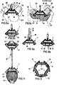
- Fig. 1 einen Querschnitt durch eine Laufschiene,
- Fig. 2 eine perspektivische Querschnittsansicht eines Hängeförder-Laufstreckenprofils,das die Laufschiene von Fig. 1 einstückig enthält,
- Fig. 3a,b Querschnitte zweier abgewandelter Hängeförder-Laufstreckenprofile mit erhöhter Belastbarkeit,
- Fig. 4a,b die Laufschiene von Fig. 1 in zwei Querschnittsdarstellungen mit Zusatzteilen,
- Fig. 5a,b,c die Laufschiene von Fig. 1 mit anderen Zusatzteilen,
- Fig. 6a,b die Laufschiene von Fig. 1 mit weiteren Zusatzteilen, jeweils im Querschnitt,
- Fig. 7 einen Querschnitt durch eine Hängeförderstrecke mit einer Zusatzfunktion,
- Fig. 8 einen Querschnitt durch eine Förderstrecke mit daran befestigten Zusatzteilen,
- Fig. 9 einen Querschnitt durch eine Stütze, die aus Profilen, aufbauend auf der Laufschiene von Fig. 1, zusammengesetzt ist,
- Fig. 10 einen Querschnitt durch eine Hängeförderstrecke mit Zusatzeinrichtungen,
- Fig. 11 einen Querschnitt durch eine Schräg-Hängeförderstrecke mit Zusatzeinrichtungen,
- Fig. 12a,b Querschnitte durch eine Behälterförderstrecke mit liegendem Laufstreckenprofil,
- Fig. 13 einen Teil einer abgestützten Förderstrecke, und
- Fig. 14 ein Detail aus Fig. 13.
- 1 shows a cross section through a running rail,
- FIG. 2 is a cross-sectional perspective view of a overhead conveyor track profile that includes the track of FIG. 1 in one piece;
- 3a, b cross sections of two modified overhead conveyor track profiles with increased resilience,
- 4a, b the track of Fig. 1 in two cross-sectional views with additional parts,
- 5a, b, c the track of Fig. 1 with other additional parts,
- 6a, b the track of Fig. 1 with additional parts, each in cross section,
- 7 shows a cross section through a suspended conveyor line with an additional function,
- 8 shows a cross section through a conveyor line with attached additional parts,
- 9 shows a cross section through a support which is composed of profiles, building on the running rail of FIG. 1,
- 10 shows a cross section through a suspended conveyor line with additional devices,
- 11 shows a cross section through an inclined overhead conveyor line with additional devices,
- 12a, b cross sections through a container conveyor section with a horizontal running section profile,
- 13 shows a part of a supported conveyor line, and
- 14 shows a detail from FIG. 13.
Eine Laufschiene 1 gemäß Fig. 1, beispielsweise ein aus Leichtmetall- oder einer Leichtmetallegierung bestehendes Strangguß- oder -preßprofil,ist entweder für sich alleine verwendbar oder gemäß Fig. 2 mit einem Tragsteg 15 und einem zur Laufschiene 1 spiegelbildlichen Tragprofil 2a einstückig in ein Laufstreckenprofil 20 integriert. Die Laufschiene 1 gemäß Fig. 1 besitzt zwei nach oben dachförmig zusammenlaufende Schenkel 2 ,die außenseitig Laufbahnen 3 für.z.B. in Fig. 5a gezeigte/Laufrollen 54 und 55 eines Laufrollenpaares 53 bilden, die in einem ihre schräg stehenden Achsen 56 miteinander verbindenden Bügel 57 gehalten sind, an dem nicht-dargestellte Transportmittel hängen. Der Bügel 57 hat unterhalb der Laufschiene 1 eine das Ausheben und Aushängen der Laufrollen 54,55 gestattende Ausnehmung. Die Laufschiene 1 ist seitensymmetrisch bezüglich einer vertikalen Symmetrieebene S. Senkrecht zur Symmetrieebene S verbindet die Schenkel 2 ein Quersteg 4. Die Schenkel 2 enden oben in einem Querabstand zur Symmetrieebene S und werden durch einen Steg 5 miteinander verbunden, der annähernd parallel zum Quersteg 4 verläuft. Der Quersteg 4 begrenzt mit den Innenseiten der Schenkel 2 und des Stegs 5 einen Hohlraum 6, in dem gegebenenfalls Längsarmierungen 8, z.B. eingebettet oder eingegossen sind. Der freie Hohlraum 6 ist zum Unterbringen von Versorgungsleitungen oder dergl. nutzbar.A running
An den freien Enden der Schenkel 2 sind Vorsprünge 7 angeformt, die schräge Führungsflächen 9 sowie zum Quersteg 4 parallele Führungsflächen 10 besitzen. Der Winkel, den die Führungsflächen 9 mit der Symmetrieebene S einschließen beträgt 60°, während der Winkel zwischen den Rollenlaufbahnen 3 und der Symmetrieebene S ca. 45° beträgt. Die Vorsprünge 7 begrenzen mit dem Quersteg 4 eine zur Unterseite der Laufschiene 1 offene Schwalbenschwanznut 12, die durch hinterschnittene Flächen 11 außen begrenzt wird. An der Unterseite des Quersteges 4 können an die Flächen 11 angrenzende Führungsflächen 13 angeformt sein.At the free ends of the
Der Steg 5 hat bei dieser Ausführung eine ebene obere Fläche 14 und ist einstückig mit einem Tragsteg 15 vereinigt, der in der Symmetrieebene S nach oben verläuft. Beiderseits des Tragstegs 15 sind Längsnuten 18 in den Steg 15 eingeformt, die zweckmäßigerweise hinterschnitten sind. Der Tragsteg 15 enthält Durchbrechungen 16, wobei der untere Durchbrechungsrand 17 unterhalb des gedachten Schnittpunktes der Laufbahnen 3 in der Symmetrieebene S liegt.In this embodiment, the
Die Laufschiene 1 ist primär für die in Fig. 1 und 2 dargestellte Betriebslage gedacht, in der der Tragsteg 15 vertikal steht. Bei einer anderen Einbaulage des Laufstreckenprofils 20 (Fig. 2), z.B. in einer Behälterförderstrecke 63,67 gemäß den Fig. 12a,b um 90° gedreht, können die Laufrollen 54,55 des jeweiligen Bügels 57 auch gleichzeitig auf den Laufbahnen 3 der Laufschiene und des Tragprofils 21 laufen. Die neutrale Faser des Querschnitts der alleine eingesetzten Laufschiene 1 liegt annähernd im Quersteg 4 oder unmittelbar an dessen Oberfläche, während sie im Laufstreckenprofil 20 in etwa in der Längsmittelachse im Tragsteg 15 liegt.The running
Bei dem in Fig. 2 dargestellen Laufstreckenprofil 20, das als Ganzes als Strangpreßprofil einstückig hergestellt ist, liegt das Tragprofil 21 spiegelbildlich zur Laufschiene 1 und hat annähernd denselben Querschnitt wie dieses. Die tatsächliche Lage der neutralen Faser richtet sich u.a. nach der Asymmetrie der Durchbrechungen 16 im Tragsteg 15. Der obere Durchbrechungsrand 17' jeder Durchbrechung 16 liegt vom Tragprofil 21 weiter entfernt als der untere Durchbrechungsrand 16 von der Laufschiene 1. Die Durchbrechungen 16 können Langlöcher oder auch kreisrund sein. Der Tragsteg 15 geht über die Länge des Laufstreckenprofils 20 durch. Innerhalb ein- und derselben Förderstrecke (siehe z.B. Fig. 13) kann das Laufstreckenprofil entweder mit dem Tragprofil 21 oben oder mit der Laufschiene 1 oben eingesetzt sein, wobei dann das Tragprofil 21 die eigentliche Laufschiene bildet. Die jeweils gewählte Einbaulage hängt u.a. davon ab, ob mit der Asymmetrie der Durchbrechungen 16 ein Aushänge- oder einAushängesperrbereich geschaffen werden soll, wie später erläutert wird.2, which is made in one piece as an extruded profile, the
Auf den Laufbahnen 3 der Laufschiene 1 von Fig. 1 könnten Kunststofflaufschichten aufgebracht sein, die dann zweckmäßigerweise In die Längsnuten 18 und die Schwalbenschwanznut 12 formschlüssig eingehängt werden. Das Laufstreckenprofil 20 gemäß Fig. 2 kann durch in die Schwalbenschwanznut 12 des Tragprofils 21 oder in der(anderen Einbaulage) der Laufschiene 1 eingebrachte Haltestücke 73, z.B. Fig.14, an einer Abstützung, z.B. einem Stützgerüst oder Stützrost 70 gemäß Fig. 13, befestigt sein,oder auch mit einem die Schenkel des Tragprofils 21 außen umgreifenden Befestigungselement. Zu einer Seitenabhängung können auch Halteelemente 40,42 (Fig.7) in die Längsnuten 18 eingreifen.Plastic running layers could be applied to the
Bei der Ausführungsform des Laufstreckenprofils 20 gemäß Fig. 3a ist das Tragprofil 21 mit einer Schiene 22 vereinigt, z.B. durch in die Schwalbenschwanznuten 12 eingesteckte Verbindungsstücke 58 oder durch Befestigungsschrauben in der Symmetrieebene S, wodurch die Steifigkeit und Belastbarkeit des Laufstreckenprofils 20 erhöht wird. Die Schiene 22 entspricht im Profil annähernd der Laufschiene 1 bzw. dem Tragprofil 21. Allerdings hat das Profil der Schiene 22 hier keinen Tragsteg 15, sondern eine oben offene Schwalbenschwanznut 23 für Einhängeteile und einen ebenen Steg 5', der dem Quersteg 4 näherliegt, als der Steg 5 dem Quersteg 4 bei der Laufschiene gemäß Fig. 1.In the embodiment of the running
Bei der Ausführungsform von Fig. 3b ist die Schiene 22 an der Laufschiene 1 befestigt, z.B. durch Befestigungselemente 25 in der Symmetrieebene, so daß ein Hohlraum 24 freibleibt. Die Schiene 22 stützt sich an den Flächen 10 der Vorsprünge 7 der Laufschiene 1 ab. Der Rollenbügel 57 kann trotz der Schiene 22 benutzt werden.In the embodiment of Fig. 3b, the
Die Laufschiene 1 gemäß Fig. 4a hält in der Schwalbenschwanznut 12 ein einflügeliges Laufprofil 27, das mit einer Laufbahn 28 zusammen mit der Laufbahn 3 ein Laufprofil für ein Rollensystem mit hochkant stehender Rolle 32 zeigt. Es kann dies die Rolle 32 eines seitenabgehängten Rollenbügels 57 sein. Wichtig ist, daß hier hintereinander und gleichzeitig die Rollenpaare 53 mit ihren die Laufbahn 28 seitlich berührungslos übergreifenden Rollenbügeln 57 und die Rollen 32 mit ihren seitlich herabhängenden Rollenbügeln57 benutzt werden können.The running
In Stoßfugen aneinander stoßender Laufstreckenprofile können (Fig. 4a) in die Längsnuten 18 Kupplungs- oder Zentrierstifte 26 eingesetzt sein.Coupling or centering
Bei der Ausführungsform der Fig. 4b ist ein zweiflügeliges Laufprofil 27' mit zwei Laufbahnen 28 eingesetzt, so daß an beiden Seiten der Laufschiene 1 hochkant stehende Laufrollen 32 mit ihrem Rollenbügel 57 laufen können. Auch hier können gleichzeitig auch die Laufrollenpaare 3 gemäß Fig. 5a benutzt werden. Die Laufprofile 27",27 können auch von vornherein einstückig in die Laufschiene 1 integriert sein, falls grundsätzlich der Betrieb mit verschiedenen Rollensystemen gewünscht wird.In the embodiment of FIG. 4b, a two-winged running profile 27 'with two
Fig. 5a zeigt, wie die Laufrollen 54 und 55 des Laufrollenpaares 53 auf der Laufschiene 1 abgestützt sind. Die mit ihren schräg stehenden Achsen 56 durch den Bügel 57 gehaltenen Laufrollen 54,55 begrenzen mit ihren Umfängen einen Aushängespalt mit einer Aushängespaltweite A, die so bemessen ist, daß das Laufrollenpaar 53 von der Laufschiene 1 gemäß Fig. 1 und auch gemäß Fig. 5a an sich ausgehängt werden kann, indem das Laufrollenpaar 53 angehoben und dann um ca. 90° gedreht und seitlich abgezogen wird. Zu diesem Zweck ist (Fig.1) der Abstand zwischen der Unterseite des Querstegs 4 und dem unteren Durchbrechungsrand 17 kleiner als die Aushängespaltweite A. Bei der Ausführungsform von Fig. 5a ist allerdings eine Aushängesperre in Form eines Sperrteiles 29 vorgesehen, der in die Längsnut 18 der Laufschiene 1 eingesteckt und darin festgelegt ist. Er besitzt einen nach oben stehenden Rand, der das Aushängen des Laufrollenpaares 53 verhindert. Zum Aushängen ist unterhalb der Laufschiene 1 im Bügel 57 eine entsprechend geformte Ausnehmung vorgesehen.5a shows how the
Bei der Ausführungsform von Fig. 5b ist eine Aushängesperre in Form eines Klotzes 30 vorgesehen, der in die Schwalbenschwanznut 12 dort eingesetzt ist, wo ein Aushängen des Laufrollenpaares aus sicherheitstechnischen Gründen nicht erwünscht ist. Der Klotz 30 ragt so weit unter die Unterseite der Laufschiene 1, daß das Laufrollenpaar 53 nicht seitlich weggezogen werden kann.In the embodiment of FIG. 5b, a release lock in the form of a
Bei der Ausführungsform von Fig. 5c ist das zusätzliche Laufprofil 27' von Fig. 4b als Formstück 31 ausgebildet, das einen erhöhten Abschnitt 34 als Aushängesperre auch eines anderen Rollensystems mit vertikal stehenden Rollen 32, bildet, die auf den Laufbahnen 33 und 3 läuft. Der strichpunktiert angedeutete Bügel 57, der an den Laufrollen 32 hängt, läßt sich im Bereich des erhöhten Abschnittes 34 nicht so weit anheben, daß die Laufrollen 32 über die Laufbahnen 33 hinweggehoben werden könnten. Der Abschnitt 34 sperrt auch, wenn nur eine seitenabgehängte Laufrolle 32 vorgesehen ist.In the embodiment of FIG. 5c, the additional running profile 27 'of FIG. 4b is designed as a shaped piece 31, which also forms a raised
Bei Fig. 6a ist eine willkürlich betätigbare Aushängesperre in Form eines Schiebers 35 mit einem Betätigungsfortsatz 36 am Tragsteg 15 so angebracht, daß sie aus der Längsnut 18 ausgehoben und nach oben verschoben werden kann, bis das Laufrollenpaar 53 ausgehängt worden ist. Sitzt hingegen die Aushängesperre in der Längsnut 18, dann ist in diesem Bereich ein Aushängen durch die Durchbrechung 16 nicht mehr möglich.In Fig. 6a, an arbitrarily actuated lockout in the form of a
Bei der Ausführungsform von Fig. 6b ist ein willkürliches Aushängen des Laufrollenpaares dann möglich, wenn ein Sperrteil 39 gegen die Kraft einer Feder 38 in die Schwalbenschwanznut 12 hineingedrückt wird, wo er mit einer Platte 37 gehalten ist.In the embodiment of FIG. 6b, an arbitrary unhooking of the pair of rollers is possible when a locking part 39 is pressed against the force of a spring 38 into the
Die Aushängesperren der Fig. 5a,5b,5c und 6a und 6b können praktisch an beliebiger Stelle der Laufschiene 1 oder des Laufstreckenprofils 20 angebracht sein.5a, 5b, 5c and 6a and 6b can practically be attached anywhere on the running
Das Laufstreckenprofil 20 gemäß Fig. 7 ist gleichzeitig zur Benutzung zweier verschiedener Laufrollensysteme geeignet, weil in der Schwalbenschwanznut 12 des Tragprofils 21 ein Längsprofil 61 mit einer oben liegenden, konvex gewölbten Lauffläche 62 festgelegt ist, auf der eine senkrecht stehende Rolle 43 laufen kann, an der an der linken Seite ein strichliert angedeuteter Hängebügel angebracht ist. Das Laufstreckenprofil 20 ist seitenabgehängt, und zwar mittels Befestigungsteilen 40, die beiderseits des Tragsteges 15 in die Längsnuten 18 der Laufschiene 1 und des Tragprofils 21 eingesetzt und darin z.B. durch Befestigungselemente 41, festgelegt sind. An den plattenförmigen Teilen 40 ist eine seitlich auskragende Seitenabhängung 42 angebracht. Bei der Ausführungsform von Fig. 7 können auf der Laufschiene 1 die Rollenpaare 53 gemäß Fig. 4a und gleichzeitig die Laufrollen 43 laufen.7 is simultaneously suitable for using two different roller systems because in the
Bei der Ausführungsform von Fig. 8 ist das Laufstreckenprofil 20 mit höherer Tragsteghöhe ausgelegt, wobei an einer Seite des Tragsteges 15 in die Längsnuten 18 der Laufschiene 1 und des Tragprofils 21 eine Halteplatte 44 eingesetzt und festgeschraubt ist, die Aufnahmen 45 für Stromkabel oder dergl. festhält. Es können dies, z.B., auch Schleif- und Kontakteinrichtungen für eine elektrisch betriebene Hängeförderbahn sein.In the embodiment of FIG. 8, the running
Fig. 9 zeigt eine Stütze 51, die zur Abstützung einer Hängeförderstrecke oder zur Schaffung eines Stützgerüstes 70 (Fig. 13) verwendet werden kann und aus Schienen 22 besteht, wie sie gemäß den Fig. 3a und 3b verwendet sind. Die Schienen 22 sind um jeweils 1200 zueinander versetzt und miteinander durch Befestigungselemente 52 verschraubt, wobei die Flächen 9 aneinander anliegen. Es könnten auch Laufschienenabschnitte 1 gemäß Fig. 1 zu solchen Stützen verbunden werden. Ferner könnten zwei oder vier Schienen verbunden werden. Auch ebene Wandschienen könnten auf diese Weise gebildet werden. Als solche Stützen könnte auch das Laufstreckenprofil 20 eingesetzt werden, d.h., auf der Basis des Querschnitts der Laufschiene 1 gemäß Fig.1 oder der des Laufstreckenprofils 20 gemäß Fig. 2 können so zusätzliche Bauelemente baukastenartig geschaffen werden, die zum Montieren oder Aufbauen einer Förderstrecke gebraucht werden.FIG. 9 shows a
Bei der Ausführungsform von Fig. 10 ist das Laufstreckenprofil 20 für einen Rundgliederkettenförderer bestimmt, wobei in der Schwalbenschwanznut 12 des Tragprofils 21 ein Kettenrücklauf 46 und in der Schwalbenschwanznut 12 der Laufschiene 1 ein Kettenvorlauf 47 befestigt ist.In the embodiment of FIG. 10, the running
Fig. 11 zeigt ein Laufstreckenprofil 20' einer Schrägförderstrecke, bei der in der Schwalbenschwanznut 12 des Tragprofils 21 ein Kettenrücklauf 50 und in der Schwalbenschwanznut 12 der Laufschiene 1 ein Kettenvorlauf 48 angeordnet sind, in denen eine Kette 49 für auf der Laufschiene 1 laufende Laufrollenpaare geführt wird.11 shows a running track profile 20 'of an inclined conveyor track in which a
Aus den Fig. 12a und 12b ist eine um 90° gegenüber den vorher beschriebenen Betriebslagen gedrehte Betriebslage des Laufstreckenprofils 20 ersichtlich, wobei das Laufstreckenprofil 20 für eine Behältertransportanlage 63 oder 67 benutzt wird. Gemäß Fig. 12a wird das liegende Laufstreckenprofil 20 mit einem in.die Nuten 18 eingebrachten und dort festgelegten Halteteil auf einer untenliegenden Abstützung gehalten. Die Laufrollen 54,55, die im Rollenbügel 57 gehalten sind, laufen auf den obenliegenden, sich V-förmig öffnenden Laufbahnen 3 der Laufschiene und des Tragprofils des Laufstreckenprofils 20. Mit 66 ist die auf dem Rollenbügel 57 ruhende Last angedeutet.12a and 12b show an operating position of the running
Bei Fig. 12b ist das liegende Laufstreckenprofil 20 über ein Halteteil 69 in den Nuten 18 und eine Mittenaufhängung 68 aufgehängt, zu deren beiden Seiten die Laufrollen 54 und 55 des das Laufstreckenprofil 20 außen nach unten umgreifenden Rollenbügels laufen. Die Last bzw. der nicht dargestellte Behälter hängt am Rollenbügel 57.In Fig. 12b, the lying running
Aus Fig. 13 ist ein Teil einer Förderstrecke erkennbar, wobei die Förderstrecke in einem Stützgerüst oder Stützrost 70 mit zwei parallel nebeneinander verlaufenden Fahrsträngen 71,72 ausgebildet ist, deren jeder aus aneinander gestoßenen Laufstreckenprofilen 20 besteht. Das Stützgerüst ist ebenfalls aus Abschnitten des Laufstreckenprofils 20 zusammengesetzt, und zwar die oberen Querträger, die auf den Stützen 51 am Boden abgestützt sind. Gegebenenfalls können die Querträger aus den Laufstreckenprofilen 20 auch mit Deckenabhängungen 77 befestigt sein. Die Laufstreckenprofile 20 der zwei Fahrstränge 71,72 sind an der Unterseite der Querstützen befestigt, und zwar beispielsweise mit in Fig. 14 vergrößert und perspektivisch dargestellten Haltestücken 73, die in die in Fig. 13 nicht hervorgehobenen Schwalbenschwanznuten 12 an den zueinander weisenden Laufschienen 1 bzw. Tragprofilen 21 eingesetzt sind. Beim Fahrstrang 71 ist jedes Laufstreckenprofil 20 mit seinem Tragsteg 21 am Querträger des Gerüstes 70 befestigt, so daß die Laufschiene 1 unten liegt. Die Durchbrechungen 16 liegen der Laufschiene 1 so nahe, daß in diesem Bereich ein Aushängen der Rollen möglich ist. Im Fahrstrang 72 sind die Laufstreckenprofile 20 um 180° gedreht und mit den Laufschienen 1 an den Querträgern befestigt, so daß die Tragprofile 21 unten liegen, an denen die Rollenpaare laufen. Da aufgrund der asymmetrischen Lage der Durchbrechungen 16 der Abstand zwischen dem unteren Durchbrechungsrand und dem Tragprofil 21 für ein Aushängen zu groß ist, liegt hier ein Aushängesperrbereich vor, in dem die Rollenpaare nicht ausgehängt werden können.13 shows a part of a conveyor line, the conveyor line being formed in a support frame or
Das Haltestück 73 gemäß Fig. 14 besteht aus zwei kreuzartig angeordneten und miteinander verbundenen Gleitsteinteilen 74,75, wobei die Gleitsteinteile 74,75 entweder einstückig oder durch Befestigungsmittel 76 lösbar miteinander verbunden sind, so daß im letzteren Fall die Relativlage der Gleitsteinteile 74,75 verstellbar ist und diese auch von vornherein in den Schalbenschwanznuten 12 liegen und erst bei der Montage verbunden werden können, z.R.reit durch die Schenkel des Tragprofils hindurchreichenden Werkzeugen.14 consists of two cross-shaped and interconnected sliding
Mit der vorstehend erwähnten Baureihenkonzeption der Laufschiene allein sowie in dem Laufstreckenprofil und mit den Schienen 22 werden mit geringem Aufwand höhere Belastungsgrenzen erreicht als bisher. Die Laufschiene 1 und der Tragsteg 15 mit dem Tragprofil 25 können nicht nur aus Leichtmetall oder Leichtmetallegierungen stranggepreßt sein, sondern es ist auch eine Blechpreß- und Schweiß-oder eine Kunststoffausbildung, z.B. glasfaserverstärkter Kunststoff, denkbar. Möglich wäre auch eine Verbundkonstruktion aus unterschiedlichen Materialien. Allen Ausführungsvarianten gemeinsam ist ein verhältnismäßig geringes Gewicht pro Längeneinheit, eine hohe Belastbarkeit und eine hohe Torsions- und Biegefestigkeit. Die Materialpaarung mit der jeweils verwendeten Laufrolle läßt sich hinsichtlich Verschleiß und Laufgeräusch einfach optimieren. Bei der geschaffenen Profilkonzeption lassen sich unterschiedliche Anbauteile und Montageelemente leicht anschließen. Das Profil der Laufschiene 1 gestattet die problemlose Ausbildung von Auf- und Abwärtsstrecken, sowie deren Übergänge in horizontale Fahrtstrecken und die Ausbildung von Links- oder Rechtskurven. Aushängesperrbereiche lassen sich genauso leicht vorsehen wie Aushängebereiche. Durch Anbringen von Einhängeteilen läßt sich die Förderstrecke beliebig auf Seiten-, Mitten- und Bodenabhängung einstellen, da die Profilform schon im Hinblick auf eventuelle Zusatzforderungen ausgelegt ist. Auch läßt sich eine Förderstrecke unter Verwendung der Laufschiene 1 oder des Laufstreckenprofils der vorhergehenden Fig. mit Zusatzeinrichtungen oder von vornherein an andere Rollensysteme anpassen, sogar so, daß mehrere Rollensysteme gleichzeitig einsetzbar sind. Auch Behältertransportanlagen mit liegender Anordnung des Laufstreckenprofils, d.h. um 90° gedreht,sind eine mögliche Anwendung. Für Elektrohängebahnen ist das Laufstreckenprofil auch gut verwendbar, weil-am Tragsteg oder am Tragprofil ohne weiteres Schleifleitungen befestigt werden können. Da die Laufschiene 1 unterschiedlich geneigte Flächen besitzt, die ineinander übergehen, besteht die Möglichkeit, Laufrollen- oder Betriebsmittel mit unterschiedlichen Anstellwinkeln der Laufrollen abwechselnd oder gleichzeitig zur verwenden. Bei angetriebenen Streckenabschnitten können neue Antriebskonzepte in das Profil des Streckenabschnittes integriert werden, z.B. Kettenförderer und dergl. Auch auf dem Tragprofil können Betriebsmittel laufen, wenn die Förderstrecke seiten- oder mittenabgehängt. ist. Ein Schweißen der Abschnitte kann entfallen, weil die Verbindung auf einfachere Weise genauso tragfähig wird. Eine Nachbehandlung oder Oberflächen veredelung ist bei Leichtmetall oder Leichtmetallegierung als Basismaterial entbehrlich. Es kann jedoch eine Eloxierung aus dekorativen Gründen und zur Oberflächenveredelung vorgesehen werden. Genauso ist aber eine individuelle Farbgebung zur Hervorhebung unterschiedlich wichtiger Fahrtstreckenabschnitte möglich.With the above-mentioned series design of the running track alone, as well as in the running track profile and with the running tracks 22, higher load limits can be achieved with little effort than before. The running
Claims (29)
Größe und Anordnung der Laufbahnen (3) dem Laufschienenprofil im wesentlichen gleich ist, und daß das Tragprofil (21), der Tragsteg (15) und Laufschiene (1) als ein Förderstreckenprofil (20) einstückig ausgebildet sind, in dem das Tragprofil (21) spiegelbildlich zur Laufschiene (1) angeordnet ist,und wobei die Förderstrecke aus aneinandergesetzten, vorzugsweise miteinander verbundenen, Förderstreckenprofilen (20) zusammengesetzt ist.12. Track, in particular according to at least one of claims 1 to 11, characterized in that the support profile (21) in cross section,
The size and arrangement of the raceways (3) is essentially the same as the running rail profile, and that the supporting profile (21), the supporting web (15) and the running rail (1) are integrally formed as a conveyor section profile (20) in which the supporting profile (21) is arranged in mirror image to the running rail (1), and wherein the conveyor track is composed of stacked, preferably interconnected, conveyor track profiles (20).
Priority Applications (1)
| Application Number | Priority Date | Filing Date | Title |
|---|---|---|---|
| AT86113896T ATE49570T1 (en) | 1985-10-07 | 1986-10-07 | RAIL. |
Applications Claiming Priority (2)
| Application Number | Priority Date | Filing Date | Title |
|---|---|---|---|
| DE3535758 | 1985-10-07 | ||
| DE19853535758 DE3535758A1 (en) | 1985-10-07 | 1985-10-07 | RUNNING RAIL |
Related Child Applications (1)
| Application Number | Title | Priority Date | Filing Date |
|---|---|---|---|
| EP88120835.9 Division-Into | 1988-12-13 |
Publications (2)
| Publication Number | Publication Date |
|---|---|
| EP0218237A1 true EP0218237A1 (en) | 1987-04-15 |
| EP0218237B1 EP0218237B1 (en) | 1990-01-17 |
Family
ID=6282969
Family Applications (1)
| Application Number | Title | Priority Date | Filing Date |
|---|---|---|---|
| EP86113896A Expired - Lifetime EP0218237B1 (en) | 1985-10-07 | 1986-10-07 | Running rail |
Country Status (8)
| Country | Link |
|---|---|
| US (1) | US4779537A (en) |
| EP (1) | EP0218237B1 (en) |
| JP (1) | JPH0786042B2 (en) |
| AT (1) | ATE49570T1 (en) |
| CA (1) | CA1267102A (en) |
| CS (1) | CS272220B2 (en) |
| DD (1) | DD249893A5 (en) |
| DE (1) | DE3535758A1 (en) |
Cited By (3)
| Publication number | Priority date | Publication date | Assignee | Title |
|---|---|---|---|---|
| EP0320047A1 (en) * | 1987-12-09 | 1989-06-14 | Key-West v.o.f. | Rail construction |
| WO2012068691A1 (en) * | 2010-11-26 | 2012-05-31 | Ferag Ag | Conveying device |
| CN113279292A (en) * | 2021-02-25 | 2021-08-20 | 李建波 | King-shaped straight rail and horizontal Y-shaped rail and vertical Y-shaped rail formed by king-shaped straight rails |
Families Citing this family (10)
| Publication number | Priority date | Publication date | Assignee | Title |
|---|---|---|---|---|
| DE3721658A1 (en) * | 1987-07-01 | 1989-01-12 | Schierholz Kg Louis | TRACK RAIL ARRANGEMENT OF A HANGING CONVEYOR SYSTEM |
| JPH11503798A (en) * | 1994-01-03 | 1999-03-30 | シモレックス リミテッド | Trajectory for classification, management and transport processing equipment |
| FR2757549B1 (en) * | 1996-12-19 | 1999-01-29 | Lohr Ind | GUIDE RAIL FOR A SELF-GUIDING ROAD VEHICLE |
| DE29803496U1 (en) * | 1998-02-27 | 1999-07-01 | Wf Logistik Gmbh | Rail for a overhead conveyor |
| ES2168873B1 (en) * | 1998-05-20 | 2003-11-01 | Ilerferro S L | ELEVATED TRANSFER MECHANICAL SYSTEM, ESPECIALLY APPLICABLE TO SUSPENDED TRANSPORT OF FERRALLA, FOR THE CONSTRUCTION OF FERRALLA ARMOR. |
| US6273341B1 (en) | 2000-03-24 | 2001-08-14 | Ahmed Debabi | Non-derailable train system including a movable crossing platform |
| DE102006002283A1 (en) * | 2006-01-18 | 2007-07-19 | Sickert & Hafner Gmbh Automotive Systems | Conveyor system for production-line manufacturing has a running rail for moving a bogie truck or a carrier for material to be conveyed along a supply track |
| FR2963380B1 (en) | 2010-06-01 | 2012-08-24 | Nergeco Sa | QUICK DOOR |
| WO2017103953A1 (en) * | 2015-12-18 | 2017-06-22 | Rem Tec S.R.L. | Handling system for solar energy receptor devices |
| US10638849B2 (en) | 2016-10-28 | 2020-05-05 | Steelcase Inc. | Convertible body support structure |
Citations (4)
| Publication number | Priority date | Publication date | Assignee | Title |
|---|---|---|---|---|
| FR1142174A (en) * | 1956-02-27 | 1957-09-13 | Advanced chain conveyor | |
| DE1940256A1 (en) * | 1969-08-07 | 1971-02-18 | Ralph Modellkleidung Ralph Lou | Conveyor device, especially for in-house haulage in the clothing industry |
| EP0139915A1 (en) * | 1983-08-13 | 1985-05-08 | R. Stahl Fördertechnik GmbH | Supporting rail arrangement for a suspended railroad or the like |
| DE3401183A1 (en) * | 1983-08-13 | 1985-07-25 | R. Stahl Fördertechnik GmbH, 7000 Stuttgart | Support rail arrangement for suspension railways, cranes or the like |
Family Cites Families (11)
| Publication number | Priority date | Publication date | Assignee | Title |
|---|---|---|---|---|
| US1115029A (en) * | 1914-02-07 | 1914-10-27 | James A Shepard | Elevated trackway. |
| US3352252A (en) * | 1965-12-28 | 1967-11-14 | Pullman Inc | Overhead rail design |
| DE1806381C3 (en) * | 1968-10-31 | 1975-10-30 | Rene Blaser, Hebe- Und Foerderanlagen Maschinenbau, Luzern (Schweiz) | Self-supporting running track for monorails |
| JPS5349198U (en) * | 1976-09-29 | 1978-04-25 | ||
| JPS53124878A (en) * | 1977-04-07 | 1978-10-31 | Mineo Fujita | Suspension rail made of angle steel for vinyl plastic hothous |
| US4265181A (en) * | 1978-11-13 | 1981-05-05 | Columbus Mckinnon Corporation | Rolling bearing wheel and hub support combination |
| DE3019301C2 (en) * | 1980-05-21 | 1982-06-24 | R. Stahl Gmbh & Co, 7000 Stuttgart | Cantilever track for monorail suspension systems |
| DE3019644C2 (en) * | 1980-05-22 | 1986-10-02 | Franz 8741 Unterelsbach Gärtner | Conveyor |
| DE3122428C2 (en) * | 1981-06-05 | 1985-11-21 | Franz 8741 Unterelsbach Gärtner | Conveyor element movable on a running rail |
| FR2508949A1 (en) * | 1981-07-01 | 1983-01-07 | Tourtellier Sa Ets | MONORAIL |
| DE3546923C2 (en) * | 1984-06-05 | 1996-02-15 | Franz Gaertner | Overhead transporter system for factory |
-
1985
- 1985-10-07 DE DE19853535758 patent/DE3535758A1/en active Granted
-
1986
- 1986-10-01 CS CS867062A patent/CS272220B2/en not_active IP Right Cessation
- 1986-10-03 DD DD86295007A patent/DD249893A5/en not_active IP Right Cessation
- 1986-10-06 CA CA000519839A patent/CA1267102A/en not_active Expired - Lifetime
- 1986-10-07 JP JP61238963A patent/JPH0786042B2/en not_active Expired - Fee Related
- 1986-10-07 AT AT86113896T patent/ATE49570T1/en not_active IP Right Cessation
- 1986-10-07 EP EP86113896A patent/EP0218237B1/en not_active Expired - Lifetime
- 1986-10-07 US US06/916,301 patent/US4779537A/en not_active Expired - Lifetime
Patent Citations (4)
| Publication number | Priority date | Publication date | Assignee | Title |
|---|---|---|---|---|
| FR1142174A (en) * | 1956-02-27 | 1957-09-13 | Advanced chain conveyor | |
| DE1940256A1 (en) * | 1969-08-07 | 1971-02-18 | Ralph Modellkleidung Ralph Lou | Conveyor device, especially for in-house haulage in the clothing industry |
| EP0139915A1 (en) * | 1983-08-13 | 1985-05-08 | R. Stahl Fördertechnik GmbH | Supporting rail arrangement for a suspended railroad or the like |
| DE3401183A1 (en) * | 1983-08-13 | 1985-07-25 | R. Stahl Fördertechnik GmbH, 7000 Stuttgart | Support rail arrangement for suspension railways, cranes or the like |
Cited By (6)
| Publication number | Priority date | Publication date | Assignee | Title |
|---|---|---|---|---|
| EP0320047A1 (en) * | 1987-12-09 | 1989-06-14 | Key-West v.o.f. | Rail construction |
| WO2012068691A1 (en) * | 2010-11-26 | 2012-05-31 | Ferag Ag | Conveying device |
| US9254962B2 (en) | 2010-11-26 | 2016-02-09 | Ferag Ag | Conveying device |
| US9511941B2 (en) | 2010-11-26 | 2016-12-06 | Ferag Ag | Conveying device |
| CN113279292A (en) * | 2021-02-25 | 2021-08-20 | 李建波 | King-shaped straight rail and horizontal Y-shaped rail and vertical Y-shaped rail formed by king-shaped straight rails |
| CN113279292B (en) * | 2021-02-25 | 2023-07-14 | 亚轨科技(成都)有限公司 | Sub-shape straight rail and horizontal Y-shaped rail and vertical Y-shaped rail formed by same |
Also Published As
| Publication number | Publication date |
|---|---|
| CS706286A2 (en) | 1990-03-14 |
| CS272220B2 (en) | 1991-01-15 |
| DE3535758A1 (en) | 1987-04-16 |
| EP0218237B1 (en) | 1990-01-17 |
| DE3535758C2 (en) | 1989-06-15 |
| JPS62175311A (en) | 1987-08-01 |
| US4779537A (en) | 1988-10-25 |
| CA1267102A (en) | 1990-03-27 |
| JPH0786042B2 (en) | 1995-09-20 |
| DD249893A5 (en) | 1987-09-23 |
| ATE49570T1 (en) | 1990-02-15 |
Similar Documents
| Publication | Publication Date | Title |
|---|---|---|
| EP0040292B1 (en) | Freely supported rail for suspended monorail vehicles | |
| EP0752968B1 (en) | Suspension conveyor system | |
| EP0137153B1 (en) | Supporting rail arrangement for suspended railroads, cranes or the like | |
| EP0218237A1 (en) | Running rail | |
| EP0572936B1 (en) | Rail | |
| DE4435641C2 (en) | Sliding sash for closing as needed, especially an open side of balconies, conservatories and the like. the like | |
| EP0128391B1 (en) | Sliding gate movable along a curve | |
| EP0398296B1 (en) | Slaughter-house conveyor | |
| DE2737348A1 (en) | MONORAR RAILWAY WITH DEVICES FOR THE POWER SUPPLY FOR VEHICLES WITH SELF-DRIVEN ELECTRIC MOTORS | |
| DE3814535C2 (en) | ||
| EP0679788B1 (en) | Trolley as well as rail and sliding assembly | |
| EP1207766B1 (en) | Cantilever type shelf | |
| EP0318057B1 (en) | Running rail profile for hanging conveyor | |
| EP1132562A2 (en) | Corner reinforcements or struts for sliding wings | |
| WO1997009484A1 (en) | Articulated rail connection | |
| DE19526550A1 (en) | Sliding door with rail and carriages | |
| DE3214437C2 (en) | Cantilever track for monorail suspension systems | |
| DE3546621C2 (en) | Rail for suspension-type conveying railways | |
| EP0141212B1 (en) | Rail for a monorail suspension track | |
| EP4038008B1 (en) | Support for a trolley, and overhead transport device comprising such a support | |
| DE8126440U1 (en) | FRAME FOR CONVEYOR DEVICES | |
| DE3338839A1 (en) | DRIVE RAIL FOR RAILWAY RAILWAY | |
| DE19935529A1 (en) | Attachment device for the runner rail of a sliding gate | |
| AT502612B1 (en) | SECTIONAL | |
| DE2628301A1 (en) | Sliding partition wall panels - are suspended from overhead runner by pulleys running in grooves in panel top |
Legal Events
| Date | Code | Title | Description |
|---|---|---|---|
| PUAI | Public reference made under article 153(3) epc to a published international application that has entered the european phase |
Free format text: ORIGINAL CODE: 0009012 |
|
| AK | Designated contracting states |
Kind code of ref document: A1 Designated state(s): AT CH FR GB IT LI |
|
| 17P | Request for examination filed |
Effective date: 19870604 |
|
| 17Q | First examination report despatched |
Effective date: 19880729 |
|
| RAP1 | Party data changed (applicant data changed or rights of an application transferred) |
Owner name: VEIT TRANSPO GMBH |
|
| GRAA | (expected) grant |
Free format text: ORIGINAL CODE: 0009210 |
|
| AK | Designated contracting states |
Kind code of ref document: B1 Designated state(s): AT CH FR GB IT LI |
|
| REF | Corresponds to: |
Ref document number: 49570 Country of ref document: AT Date of ref document: 19900215 Kind code of ref document: T |
|
| XX | Miscellaneous (additional remarks) |
Free format text: TEILANMELDUNG 88120835.9 EINGEREICHT AM 07/10/86. |
|
| ET | Fr: translation filed | ||
| GBT | Gb: translation of ep patent filed (gb section 77(6)(a)/1977) | ||
| ITF | It: translation for a ep patent filed |
Owner name: BUGNION S.P.A. |
|
| PLBE | No opposition filed within time limit |
Free format text: ORIGINAL CODE: 0009261 |
|
| STAA | Information on the status of an ep patent application or granted ep patent |
Free format text: STATUS: NO OPPOSITION FILED WITHIN TIME LIMIT |
|
| 26N | No opposition filed | ||
| ITTA | It: last paid annual fee | ||
| REG | Reference to a national code |
Ref country code: FR Ref legal event code: SN |
|
| PGFP | Annual fee paid to national office [announced via postgrant information from national office to epo] |
Ref country code: FR Payment date: 19931015 Year of fee payment: 8 |
|
| ITPR | It: changes in ownership of a european patent |
Owner name: CAMBIO RAGIONE SOCIA;SUM SYSTEMBAU UND MONTAGE GMB |
|
| REG | Reference to a national code |
Ref country code: CH Ref legal event code: PUE Owner name: RSL LOGISTIK GMBH & CO. Ref country code: CH Ref legal event code: PFA Free format text: SUM SYSTEMBAU UND MONTAGE GMBH |
|
| PG25 | Lapsed in a contracting state [announced via postgrant information from national office to epo] |
Ref country code: FR Effective date: 19950630 |
|
| REG | Reference to a national code |
Ref country code: FR Ref legal event code: ST |
|
| REG | Reference to a national code |
Ref country code: GB Ref legal event code: 732E |
|
| REG | Reference to a national code |
Ref country code: CH Ref legal event code: PUE Owner name: RSL LOGISTIK GMBH & CO. TRANSFER- WF LOGISTIK GMBH |
|
| REG | Reference to a national code |
Ref country code: GB Ref legal event code: 732E |
|
| REG | Reference to a national code |
Ref country code: FR Ref legal event code: JE |
|
| REG | Reference to a national code |
Ref country code: FR Ref legal event code: JE |
|
| REG | Reference to a national code |
Ref country code: FR Ref legal event code: RN |
|
| REG | Reference to a national code |
Ref country code: FR Ref legal event code: IC |
|
| REG | Reference to a national code |
Ref country code: GB Ref legal event code: IF02 |
|
| PGFP | Annual fee paid to national office [announced via postgrant information from national office to epo] |
Ref country code: AT Payment date: 20021022 Year of fee payment: 17 |
|
| PGFP | Annual fee paid to national office [announced via postgrant information from national office to epo] |
Ref country code: GB Payment date: 20021023 Year of fee payment: 17 |
|
| PGFP | Annual fee paid to national office [announced via postgrant information from national office to epo] |
Ref country code: CH Payment date: 20021029 Year of fee payment: 17 |
|
| PG25 | Lapsed in a contracting state [announced via postgrant information from national office to epo] |
Ref country code: GB Free format text: LAPSE BECAUSE OF NON-PAYMENT OF DUE FEES Effective date: 20031007 Ref country code: AT Free format text: LAPSE BECAUSE OF NON-PAYMENT OF DUE FEES Effective date: 20031007 |
|
| PG25 | Lapsed in a contracting state [announced via postgrant information from national office to epo] |
Ref country code: LI Free format text: LAPSE BECAUSE OF NON-PAYMENT OF DUE FEES Effective date: 20031031 Ref country code: CH Free format text: LAPSE BECAUSE OF NON-PAYMENT OF DUE FEES Effective date: 20031031 |
|
| GBPC | Gb: european patent ceased through non-payment of renewal fee |
Effective date: 20031007 |
|
| REG | Reference to a national code |
Ref country code: CH Ref legal event code: PL |
|
| PG25 | Lapsed in a contracting state [announced via postgrant information from national office to epo] |
Ref country code: IT Free format text: LAPSE BECAUSE OF NON-PAYMENT OF DUE FEES;WARNING: LAPSES OF ITALIAN PATENTS WITH EFFECTIVE DATE BEFORE 2007 MAY HAVE OCCURRED AT ANY TIME BEFORE 2007. THE CORRECT EFFECTIVE DATE MAY BE DIFFERENT FROM THE ONE RECORDED. Effective date: 20051007 |