EP0218164A2 - Drawer - Google Patents
Drawer Download PDFInfo
- Publication number
- EP0218164A2 EP0218164A2 EP86113330A EP86113330A EP0218164A2 EP 0218164 A2 EP0218164 A2 EP 0218164A2 EP 86113330 A EP86113330 A EP 86113330A EP 86113330 A EP86113330 A EP 86113330A EP 0218164 A2 EP0218164 A2 EP 0218164A2
- Authority
- EP
- European Patent Office
- Prior art keywords
- drawer
- pull
- slider
- frame
- frames
- Prior art date
- Legal status (The legal status is an assumption and is not a legal conclusion. Google has not performed a legal analysis and makes no representation as to the accuracy of the status listed.)
- Granted
Links
- 239000002991 molded plastic Substances 0.000 abstract 1
- 238000002347 injection Methods 0.000 description 2
- 239000007924 injection Substances 0.000 description 2
- 235000004443 Ricinus communis Nutrition 0.000 description 1
- 240000000528 Ricinus communis Species 0.000 description 1
- 238000010276 construction Methods 0.000 description 1
- 239000000463 material Substances 0.000 description 1
- 230000007246 mechanism Effects 0.000 description 1
- 239000002184 metal Substances 0.000 description 1
Images


Classifications
-
- A—HUMAN NECESSITIES
- A47—FURNITURE; DOMESTIC ARTICLES OR APPLIANCES; COFFEE MILLS; SPICE MILLS; SUCTION CLEANERS IN GENERAL
- A47B—TABLES; DESKS; OFFICE FURNITURE; CABINETS; DRAWERS; GENERAL DETAILS OF FURNITURE
- A47B88/00—Drawers for tables, cabinets or like furniture; Guides for drawers
- A47B88/40—Sliding drawers; Slides or guides therefor
- A47B88/483—Sliding drawers; Slides or guides therefor with single extensible guides or parts
-
- A—HUMAN NECESSITIES
- A47—FURNITURE; DOMESTIC ARTICLES OR APPLIANCES; COFFEE MILLS; SPICE MILLS; SUCTION CLEANERS IN GENERAL
- A47B—TABLES; DESKS; OFFICE FURNITURE; CABINETS; DRAWERS; GENERAL DETAILS OF FURNITURE
- A47B2210/00—General construction of drawers, guides and guide devices
- A47B2210/0002—Guide construction for drawers
- A47B2210/0029—Guide bearing means
- A47B2210/0043—Wheels
-
- A—HUMAN NECESSITIES
- A47—FURNITURE; DOMESTIC ARTICLES OR APPLIANCES; COFFEE MILLS; SPICE MILLS; SUCTION CLEANERS IN GENERAL
- A47B—TABLES; DESKS; OFFICE FURNITURE; CABINETS; DRAWERS; GENERAL DETAILS OF FURNITURE
- A47B2210/00—General construction of drawers, guides and guide devices
- A47B2210/0002—Guide construction for drawers
- A47B2210/0051—Guide position
- A47B2210/0059—Guide located at the side of the drawer
-
- A—HUMAN NECESSITIES
- A47—FURNITURE; DOMESTIC ARTICLES OR APPLIANCES; COFFEE MILLS; SPICE MILLS; SUCTION CLEANERS IN GENERAL
- A47B—TABLES; DESKS; OFFICE FURNITURE; CABINETS; DRAWERS; GENERAL DETAILS OF FURNITURE
- A47B2210/00—General construction of drawers, guides and guide devices
- A47B2210/02—Drawers with hollow lateral walls in two parts
Definitions
- the invention relates to a drawer with pull-out rails fastened to the side drawer frames, which roll on castor-side castors, with a slider being arranged on the drawer frames or the pull-out rails at the rear, which engages on a body-side mounting rail and can be moved along the latter and the drawer frames are double-walled .
- Drawers with drawer frames made of plastic and metal pull-out rails are well known in modern furniture construction.
- Drawers have also become known which have a slider at the rear which can be moved along a body-side mounting rail and which rolls on a body-side roller at the front.
- the drawer is held in a tiltable manner by the sliders, which have slots into each of which a horizontal web of a mounting rail projects.
- the object of the present invention is to improve a drawer of the type mentioned at the outset in that the assembly of the three parts interacting for the movement of the drawer, namely the drawer frame, the rail and the slide, is facilitated and improved.
- the slider is inserted into the drawer frame on each side of the drawer and is located between the inner and outer wall of the drawer frame and in that the pull-out rail is inserted with its rear end into the slider.
- the slider is inserted into the drawer frame from behind and has a nose which engages behind a projection of the drawer frame or engages in a recess in the drawer frame.
- the nose prevents a glider from un deliberately separates from the drawer frame and thus there is no longer any hold for the pull-out rail.
- An embodiment of the invention provides that the pull-out rail has a U-profile, but at its rear end a section with an L-profile which projects into the slider.
- Both separate drawer frames can be provided, e.g. B. a drawer frame on each side of the drawer and a drawer frame that forms the rear wall of the drawer, the drawer frames being connected to one another in a conventional manner, for example by snap-in mechanisms, or the complete border of the drawer can be made from one piece on the side and rear.
- the drawer frames have a vertical web with an opening through which the pull-out rail protrudes.
- the pull-out rails advantageously protrude into a blind hole in the slider.
- An embodiment of the invention provides that the drawer frames are double-walled and at least have an inward projection on both sides at the front and the pull-out rails rest on these projections.
- drawer frames which are advantageously injection molded parts, chambers can be formed, each of which a slider completely fills. As a result, the slider is compactly fastened in the drawer frame.
- the slider will generally be made of a plastic material, it has a certain elasticity and can enclose the pull-out rail with slight pressure within the chamber.
- FIG. 1 shows a side view of a drawer according to the invention, the drawer being inserted into a furniture body
- Fig. 2 shows a side view of the drawer according to the invention while it is in the extended position
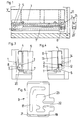
- Fig. 3 shows a view in the direction of arrow H of FIG. 1
- FIG. 4 shows a view in the direction of arrow V of FIG. 1
- FIG. 5 shows a side view of the slider
- FIG. 6 shows a side view of an extension rail
- FIG. 7 shows a top view of a pull-out rail
- FIG. 8 shows a front view of a pull-out rail
- FIG. 9 shows a side view of a drawer frame
- FIG. 10 shows a view from the direction of arrow H of FIG. 9, which shows FIG. 11 a view from the direction of arrow V of FIG. 9
- FIG. 12 shows a plan view of a drawer frame.
- the parts of the drawer that are essential according to the invention are the pull-out rail 2, slider 3 and the drawer frame 4, which is preferably injection molded from plastic.
- a mounting rail 1 is fastened to the side wall of the body.
- a roller 5 is also mounted on the front of the body side wall. This roller 5 could, however, also be replaced by a slider if the drawer only has to absorb very low loads.
- the drawer with the pull-out rails 2 is supported on the rollers 5 and, with the sliders 3, each comprises a horizontal web 8 of the support rail.
- the pull-out rail has two side webs 9, 10, wherein none of the side webs is longer than the radius of the roller 5. If the pull-out rail 2 is inserted into the drawer frame 4, it is supported with the two side webs 9, 10 on projections 11, 12 of the walls 13, 14 of the drawer frame 4.
- the projection 11 is base-like and the projection 12 is designed as an unbent flap.
- the projections 11, 12 can either extend over the length of the drawer frame 4 or can be arranged only in the front area.
- the pull-out rail 2 has an angled portion 15, which causes the drawer to run in in a conventional manner.
- the pull-out rail 2 is provided with a section 16 which has an L-profile. This section 16 protrudes into the slider 3.
- the slider 3 is provided with a corresponding blind hole 17 for this purpose.
- the slider 3 is inserted into the drawer frame 4 from behind.
- receiving chambers 18 are formed on the drawer frame 4. These receiving chambers 18 are essentially filled by the sliders 3, so that the Pull-out rail 2 is held in the slider 3 with a certain pressure.
- the slider 3 has a nose 19 which projects into a recess 20 in the drawer frame 4. If the slider 3 is pressed into the drawer frame 4, the nose 19 snaps into the recess 20 and the slider 3 is held immovably in the drawer frame 4.
- the slider 3 has an edge 21 which bears against the rear wall of the frame 4.
- the slider 3 also has a slot 22 through which the horizontal web 8 of the body rail 1 projects.
- the slider 3 is provided with a chamber-like recess 23, which improves the elasticity of the slider 3.
- the slot 22 of the slider 3 is made approximately X-shaped, so that two funnels 21 'are formed. In this way, the pull-out rail 2 cannot tilt in the slider 3. In addition, the sliding properties of the slider 3 are improved.
- the drawer frame 4 is provided with a vertical web 24, which has an opening 25.
- the opening 25 corresponds to the profile of the pull-out rail 2 and the pull-out rail 2 can be inserted through this opening 25 into the chamber 18 and thus into the slider 3.
- the drawer front panel is not shown in the figures of the drawing, since it is not part of the subject matter of the invention.
Abstract
Eine Schublade hat seitliche Schubladenzargen (4) aus gespritzten Kunststoffprofilen, an denen Ausziehschienen, die an korpusseitigen Laufrollen abrollen, befestigt sind. An den Schubladenzargen (4) und an den Ausziehschienen (2) sind hinten Gleiter (3) angeordnet. Die Gleiter (3) greifen an korpusseitigen Tragschienen (1) an und sind entlang diesen verschiebbar. Die Gleiter (3) sind von hinten in die Schubladenzarge (4) eingesetzt und weisen eine Nase (19) auf, die in ein Ausnehmung (20) der Schubladenzarge (4) eingreift.A drawer has side drawer frames (4) made of injection-molded plastic profiles, to which pull-out rails that roll on casters on the cabinet side are attached. Sliders (3) are arranged on the back of the drawer frames (4) and the pull-out rails (2). The sliders (3) engage on support rails (1) on the body side and can be moved along these. The sliders (3) are inserted into the drawer frame (4) from behind and have a nose (19) which engages in a recess (20) in the drawer frame (4).
Description
Die Erfindung bezieht sich auf eine Schublade mit an den seitlichen Schubladenzargen befestigten Ausziehschienen, die an korpusseitigen Laufrollen abrollen, wobei an den Schubladenzargen oder den Ausziehschienen hinten ein Gleiter angeordnet ist, der an einer korpusseitigen Tragschiene angreift und entlang dieser verschiebbar ist und die Schubladenzargen doppelwandig sind.The invention relates to a drawer with pull-out rails fastened to the side drawer frames, which roll on castor-side castors, with a slider being arranged on the drawer frames or the pull-out rails at the rear, which engages on a body-side mounting rail and can be moved along the latter and the drawer frames are double-walled .
Schubladen mit Schubladenzargen aus Kunststoff und metallischen Ausziehschienen sind im modernen Möbelbau hinlänglich bekannt. Es sind weiter Schubladen bekannt geworden, die hinten einen Gleiter aufweisen, der entlang einer korpusseitigen Tragschiene verschoben werden kann und die vorne auf einer korpusseitigen Laufrolle abrollt. Die Schublade ist durch die Gleiter, die Schlitze aufweisen, in die jeweils ein Horizontalsteg einer Tragschiene ragt, kippbar gehalten.Drawers with drawer frames made of plastic and metal pull-out rails are well known in modern furniture construction. Drawers have also become known which have a slider at the rear which can be moved along a body-side mounting rail and which rolls on a body-side roller at the front. The drawer is held in a tiltable manner by the sliders, which have slots into each of which a horizontal web of a mounting rail projects.
Aufgabe der vorliegenden Erfindung ist es, eine Schublade der eingangs erwähnten Art insofern zu verbessern, als das der Zusammenaufbau der drei für den Bewegungsablauf der Schublade zusammenwirkenden Teile, und zwar der Schubladenzarge, der Schiene und des Gleiters erleichtert und verbessert wird.The object of the present invention is to improve a drawer of the type mentioned at the outset in that the assembly of the three parts interacting for the movement of the drawer, namely the drawer frame, the rail and the slide, is facilitated and improved.
Dies wird erfindungsgemäß dadurch erreicht, daß an jeder Seite der Schublade der Gleiter in die Schubladenzarge eingesetzt ist und sich zwischen der Innen- und Außenwand der Schubladenzarge befindet und daß die Ausziehschiene mit ihrem hinteren Ende in den Gleiter eingeschoben ist.This is achieved according to the invention in that the slider is inserted into the drawer frame on each side of the drawer and is located between the inner and outer wall of the drawer frame and in that the pull-out rail is inserted with its rear end into the slider.
Vorteilhaft ist vorgesehen, daß der Gleiter von hinten in die Schubladenzarge eingesetzt ist und eine Nase aufweist, die hinter einen Vorsprung der Schubladenzarge einrastet bzw. in eine Ausnehmung der Schubladenzarge eingreift.It is advantageously provided that the slider is inserted into the drawer frame from behind and has a nose which engages behind a projection of the drawer frame or engages in a recess in the drawer frame.
Durch die Nase wird verhindert, daß sich ein Gleiter un beabsichtigt von der Schubladenzarge trennt und somit auch der Halt für die Ausziehschiene nicht mehr gegeben ist.The nose prevents a glider from un deliberately separates from the drawer frame and thus there is no longer any hold for the pull-out rail.
Ein Ausführungsbeispiel der Erfindung sieht vor, daß die Ausziehschiene U-Profil hat, aber an ihrem hinteren Ende einen Abschnitt mit L-Profil, der in den Gleiter ragt.An embodiment of the invention provides that the pull-out rail has a U-profile, but at its rear end a section with an L-profile which projects into the slider.
Es können sowohl getrennte Schubladenzargen vorgesehen sein, z. B. eine Schubladenzarge an jeder Seite der Schublade und eine Schubladenzarge, die die Schubladenrückwand bildet, wobei die Schubladenzargen auf herkömmliche Art beispielsweise durch Einschnappmechanismen miteinander verbunden sind, oder es kann die komplette Umrandung der Schublade seitlich und hinten aus einem Stück ausgeführt sein.Both separate drawer frames can be provided, e.g. B. a drawer frame on each side of the drawer and a drawer frame that forms the rear wall of the drawer, the drawer frames being connected to one another in a conventional manner, for example by snap-in mechanisms, or the complete border of the drawer can be made from one piece on the side and rear.
Um den Halt der Ausziehschienen in der Schubladenzarge zu verbessern, ist vorteilhaft vorgesehen, daß die Schubladenzargen einen Vertikalsteg aufweisen, mit einer Durchbrechung, durch die die Ausziehschiene ragt.In order to improve the hold of the pull-out rails in the drawer frame, it is advantageously provided that the drawer frames have a vertical web with an opening through which the pull-out rail protrudes.
Vorteilhaft ragen die Ausziehschienen in ein Sackloch des Gleiters.The pull-out rails advantageously protrude into a blind hole in the slider.
Ein Ausführungsbeispiel der Erfindung sieht vor, daß die Schubladenzargen doppelwandig sind und zumindestens vorn beidseitig einen nach innen gerichteten Vorsprung aufweisen und die Ausziehschienen auf diesen Vorsprüngen aufliegen.An embodiment of the invention provides that the drawer frames are double-walled and at least have an inward projection on both sides at the front and the pull-out rails rest on these projections.
In den Schubladenzargen, die vorteilhaft Spritzgießteile sind, können Kammern ausgebildet sein, die jeweils ein Gleiter vollständig ausfüllt. Dadurch ist der Gleiter jeweils kompakt in der Schubladenzarge befestigt.In the drawer frames, which are advantageously injection molded parts, chambers can be formed, each of which a slider completely fills. As a result, the slider is compactly fastened in the drawer frame.
Da der Gleiter im allgemeinen aus einem Kunststoffmaterial gefertigt sein wird, ist ihm eine gewisse Elastizität zu eigen und er kann innerhalb der Kammer die Ausziehschiene mit leichtem Druck umfassen.Since the slider will generally be made of a plastic material, it has a certain elasticity and can enclose the pull-out rail with slight pressure within the chamber.
Nachfolgend wird ein Ausführungsbeispiel der Erfindung anhand der Figuren der beiliegenden Zeichnungen eingehend beschrieben.An exemplary embodiment of the invention is described in detail below with reference to the figures in the accompanying drawings.
Die Fig. 1 zeigt eine Seitenansicht einer erfindungsgemäßen Schublade, wobei die Schublade in einen Möbelkorpus eingeschoben ist, die Fig. 2 zeigt eine Seitanansicht der erfindungsgemäßen Schublade, während diese sich in der ausgefahrenen Stellung befindet, die Fig. 3 zeigt eine Ansicht nach der Richtung des Pfeiles H der Fig. 1, die Fig. 4 zeigt eine Ansicht nach der Richtung des Pfeiles V der Fig. 1, die Fig. 5 zeigt eine Seitenansicht des Gleiters, die Fig. 6 zeigt eine Seitenansicht einer Ausziehschiene, die Fig. 7 zeigt eine Draufsicht auf eine Ausziehschiene, die Fig. 8 zeigt eine Stirnansicht einer Ausziehschiene, die Fig. 9 zeigt eine Seitenansicht einer Schubladenzarge, die Fig. 10 zeigt eine Ansicht aus der Richtung des Pfeiles H der Fig. 9, die Fig. 11 zeigt eine Ansicht aus der Richtung des Pfeiles V der Fig. 9 und die Figur 12 zeigt eine Draufsicht auf eine Schubladenzarge.Fig. 1 shows a side view of a drawer according to the invention, the drawer being inserted into a furniture body, Fig. 2 shows a side view of the drawer according to the invention while it is in the extended position, Fig. 3 shows a view in the direction of arrow H of FIG. 1, FIG. 4 shows a view in the direction of arrow V of FIG. 1, FIG. 5 shows a side view of the slider, FIG. 6 shows a side view of an extension rail, FIG. 7 shows a top view of a pull-out rail, FIG. 8 shows a front view of a pull-out rail, FIG. 9 shows a side view of a drawer frame, FIG. 10 shows a view from the direction of arrow H of FIG. 9, which shows FIG. 11 a view from the direction of arrow V of FIG. 9 and FIG. 12 shows a plan view of a drawer frame.
In der nachfolgenden Beschreibung wird jeweils nur auf eine Seite der Schublade Bezug genommen, die andere Seite ist paralog ausgebildet.In the following description, only one side of the drawer is referred to, the other side is paralogous.
Die erfindungsgemäß wesentlichen Teile der Schublade sind die Ausziehschiene 2, Gleiter 3 und die vorzugsweise aus Kunststoff gespritzte Schubladenzarge 4.The parts of the drawer that are essential according to the invention are the pull-out
In den Figuren 1 bis 4 sind noch die Schubladenrückwand mit 6 und der Schubladenboden mit 7 bezeichnet.In Figures 1 to 4, the drawer rear wall with 6 and the drawer bottom with 7 are designated.
An der Korpusseitenwand ist eine Tragschiene 1 befestigt. Ebenso an der Korpusseitenwand lagert vorne eine Laufrolle 5. Diese Laufrolle 5 könnte jedoch auch durch einen Gleiter ersetzt werden, wenn die Schublade nur sehr geringe Lasten aufnehmen muß.A
Wie aus den Figuren 1 bis 4 ersichtlich, stützt sich die Schublade mit den Ausziehschienen 2 auf den Laufrollen 5 ab und umfaßt mit den Gleitern 3 jeweils einen Horizontalsteg 8 der Tragschiene.As can be seen from FIGS. 1 to 4, the drawer with the pull-out
Die Ausziehschiene weist zwei Seitenstege 9, 10 auf, wobei keiner der Seitenstege länger als der Radius der Laufrolle 5 ist. Ist die Ausziehschiene 2 in die Schubladenzarge 4 eingesetzt, stützt sie sich mit den beiden Seitenstegen 9, 10 an Vorsprüngen 11, 12 der Wände 13, 14 der Schubladenzarge 4 ab. Dabei ist der Vorspung 11 sockelartig und der Vorsprung 12 als ungebogener Lappen ausgebildet. Die Vorsprünge 11, 12 können sich entweder über die Länge der Schubladenzarge 4 hindurchziehen, oder nur im vorderen Bereich angeordnet sein.The pull-out rail has two
Vorne weist die Ausziehschiene 2 eine Abwinkelung 15 auf, die in herkömmlicher Weise den Einlauf der Schublade bewirkt.At the front, the pull-out
Hinten ist die Ausziehschiene 2 mit einem Abschnitt 16 versehen, der L-Profil aufweist. Dieser Abschnitt 16 ragt in den Gleiter 3. Der Gleiter 3 ist dafür mit einem korrespondierenden Sackloch 17 versehen.At the rear, the pull-out
Der Gleiter 3 wird,wie aus den Figuren 1 und 2 ersichtlich, von hinten in die Schubladenzarge 4 eingesteckt. An der Schubladenzarge 4 sind dafür Aufnahmekammern 18 (siehe Figur 12) ausgebildet. Diese Aufnahmekammern 18 werden von den Gleitern 3 im wesentlichen ausgefüllt, sodaß die Ausziehschiene 2 jeweils mit einem gewissen Druck im Gleiter 3 gehalten ist.As can be seen from FIGS. 1 and 2, the
Der Gleiter 3 weist eine Nase 19 auf, die in eine Ausnehmung 20 in der Schubladenzarge 4 ragt. Wird der Gleiter 3 in die Schubladenzarge 4 hinein gedrückt, schnappt die Nase 19 in der Ausnehmung 20 ein und der Gleiter 3 ist unverrückbar in der Schubladenzarge 4 gehalten.The
Hinten weist der Gleiter 3 einen Rand 21 auf, der an der Rückwand der Zarge 4 anliegt.At the rear, the
Der Gleiter 3 weist weiters einen Schlitz 22 auf, durch den der Horizontalsteg 8 der Korpusschiene 1 ragt.The
Innen ist der Gleiter 3 mit einer kammerartigen Ausnehmung 23 versehen, was die Elastizität des Gleiters 3 verbessert.Inside, the
Wie aus den Figuren 1 und 2 ersichtlich, ist der Schlitz 22 des Gleiters 3 in etwa X-förmig ausgeführt, so daß sich zwei Trichter 21' bilden. Auf diese Art und Weise kann es zu keinem Verkanten der Ausziehschiene 2 im Gleiter 3 kommen. Außerdem werden die Gleiteigenschaften des Gleiters 3 verbessert.As can be seen from FIGS. 1 and 2, the
Bei der Kammer 18 ist die Schubladenzarge 4 mit einem senkrechten Steg 24 versehen, der eine Durchbrechung 25 aufweist. Die Durchbrechung 25 korrespondiert mit dem Profil der Ausziehschiene 2 und die Ausziehschiene 2 ist durch diese Durchbrechung 25 hindurch in die Kammer 18 und somit in den Gleiter 3 einführbar.In the
In den Figuren der Zeichnung ist die Schubladenfrontplatte nicht gezeigt, da sie nicht zum Gegenstand der Erfindung gehört.The drawer front panel is not shown in the figures of the drawing, since it is not part of the subject matter of the invention.
Claims (7)
Applications Claiming Priority (2)
| Application Number | Priority Date | Filing Date | Title |
|---|---|---|---|
| AT0288685A AT390720B (en) | 1985-10-07 | 1985-10-07 | DRAWER |
| AT2886/85 | 1985-10-07 |
Publications (3)
| Publication Number | Publication Date |
|---|---|
| EP0218164A2 true EP0218164A2 (en) | 1987-04-15 |
| EP0218164A3 EP0218164A3 (en) | 1987-08-19 |
| EP0218164B1 EP0218164B1 (en) | 1989-07-12 |
Family
ID=3541859
Family Applications (1)
| Application Number | Title | Priority Date | Filing Date |
|---|---|---|---|
| EP86113330A Expired EP0218164B1 (en) | 1985-10-07 | 1986-09-27 | Drawer |
Country Status (8)
| Country | Link |
|---|---|
| US (1) | US4749243A (en) |
| EP (1) | EP0218164B1 (en) |
| JP (1) | JPS6290109A (en) |
| AT (1) | AT390720B (en) |
| AU (1) | AU577478B2 (en) |
| CA (1) | CA1267678A (en) |
| DE (2) | DE3664251D1 (en) |
| IT (1) | IT211099Z2 (en) |
Cited By (1)
| Publication number | Priority date | Publication date | Assignee | Title |
|---|---|---|---|---|
| EP0503234A1 (en) * | 1991-03-09 | 1992-09-16 | Bene Büromöbel Kg | Drawer runner for drawers preferably made of metal |
Families Citing this family (2)
| Publication number | Priority date | Publication date | Assignee | Title |
|---|---|---|---|---|
| US5628552A (en) * | 1995-11-20 | 1997-05-13 | O'barr; Terry | Portable multi-compartment drawer |
| US6834923B2 (en) | 2003-02-10 | 2004-12-28 | Jonathan Manufacturing Corporation | Miniature solid bearing slide assembly |
Citations (3)
| Publication number | Priority date | Publication date | Assignee | Title |
|---|---|---|---|---|
| US3201187A (en) * | 1963-06-10 | 1965-08-17 | Ronthor Reiss Corp | Drawer back bearing |
| DE2416361A1 (en) * | 1974-04-04 | 1975-10-16 | Bbp Kunststoffwerk | Plastics one-piece drawer with double side walls - is fitted with strip runners which fill in cavity to give solid appearance |
| GB1447036A (en) * | 1972-08-26 | 1976-08-25 | Lb Plastics Ltd | Drawers |
Family Cites Families (7)
| Publication number | Priority date | Publication date | Assignee | Title |
|---|---|---|---|---|
| US3650592A (en) * | 1968-12-23 | 1972-03-21 | Cole C Williams | Drawer with guide system |
| US3826554A (en) * | 1971-09-09 | 1974-07-30 | Groovfold Inc | Drawer construction |
| SE429398B (en) * | 1976-07-14 | 1983-09-05 | Lb Plastics Ltd | A SIDE PIECE OF AN EXTRACT DRAW AND AN EXTRACT DRAW |
| CA1107798A (en) * | 1977-07-23 | 1981-08-25 | Terence Hardy | Drawers |
| CA1148204A (en) * | 1979-11-02 | 1983-06-14 | Leon G. Litchfield | Drawers |
| DE3072060D1 (en) * | 1980-01-11 | 1988-02-04 | Lb Plastics Ltd | Improvements relating to drawers |
| DE8307469U1 (en) * | 1983-03-15 | 1983-10-13 | Bbp-Kunststoffwerk Marbach Baier & Co, 7142 Marbach | PLASTIC DRAWER FOR FURNITURE |
-
1985
- 1985-10-07 AT AT0288685A patent/AT390720B/en not_active IP Right Cessation
-
1986
- 1986-09-26 US US06/911,986 patent/US4749243A/en not_active Expired - Fee Related
- 1986-09-27 DE DE8686113330T patent/DE3664251D1/en not_active Expired
- 1986-09-27 EP EP86113330A patent/EP0218164B1/en not_active Expired
- 1986-09-30 IT IT8606741U patent/IT211099Z2/en active
- 1986-09-30 AU AU63300/86A patent/AU577478B2/en not_active Ceased
- 1986-10-06 CA CA000519906A patent/CA1267678A/en not_active Expired - Fee Related
- 1986-10-07 DE DE8627294U patent/DE8627294U1/de not_active Expired
- 1986-10-07 JP JP61237273A patent/JPS6290109A/en active Pending
Patent Citations (3)
| Publication number | Priority date | Publication date | Assignee | Title |
|---|---|---|---|---|
| US3201187A (en) * | 1963-06-10 | 1965-08-17 | Ronthor Reiss Corp | Drawer back bearing |
| GB1447036A (en) * | 1972-08-26 | 1976-08-25 | Lb Plastics Ltd | Drawers |
| DE2416361A1 (en) * | 1974-04-04 | 1975-10-16 | Bbp Kunststoffwerk | Plastics one-piece drawer with double side walls - is fitted with strip runners which fill in cavity to give solid appearance |
Cited By (1)
| Publication number | Priority date | Publication date | Assignee | Title |
|---|---|---|---|---|
| EP0503234A1 (en) * | 1991-03-09 | 1992-09-16 | Bene Büromöbel Kg | Drawer runner for drawers preferably made of metal |
Also Published As
| Publication number | Publication date |
|---|---|
| IT8606741V0 (en) | 1986-09-30 |
| JPS6290109A (en) | 1987-04-24 |
| IT211099Z2 (en) | 1989-02-13 |
| US4749243A (en) | 1988-06-07 |
| ATA288685A (en) | 1989-12-15 |
| CA1267678A (en) | 1990-04-10 |
| AU577478B2 (en) | 1988-09-22 |
| AT390720B (en) | 1990-06-25 |
| DE8627294U1 (en) | 1986-12-04 |
| AU6330086A (en) | 1987-04-09 |
| EP0218164A3 (en) | 1987-08-19 |
| EP0218164B1 (en) | 1989-07-12 |
| DE3664251D1 (en) | 1989-08-17 |
Similar Documents
| Publication | Publication Date | Title |
|---|---|---|
| AT401717B (en) | LOCKING DEVICE FOR DRAWERS | |
| EP0545329B1 (en) | Drawer slide fitting | |
| EP2916688B1 (en) | Drawer pull out guide | |
| EP0706012B1 (en) | Cooking device | |
| DE3035927C2 (en) | Guide rail set, especially for drawers | |
| DE2846764C2 (en) | Pull-out guide for drawers or the like. | |
| EP0780071A2 (en) | Drawer with ball drawer slide | |
| EP0761133B1 (en) | Set of pull-out guides for drawers | |
| AT392883B (en) | DRAWER EXTENSION | |
| EP0218164B1 (en) | Drawer | |
| EP0809956A2 (en) | Drawer device for a slidable, flush-mounted element incorporated in a cupboard unit | |
| AT402779B (en) | EXTENDING GUIDE FOR DRAWER | |
| AT312851B (en) | Pull-out with unwinding bodies, preferably with rollers, for pull-out furniture parts | |
| EP0528218B1 (en) | Piece of furniture with a swinging-sliding door, in particular a cupboard | |
| EP0855487B1 (en) | Guiding device for a sliding door | |
| DE3010089A1 (en) | EXTENSION GUIDE FOR DRAWERS OR THE LIKE | |
| EP0333981A1 (en) | Fitting for sliding/rotating doors for furniture | |
| DE2908391A1 (en) | Guide fitting for furniture drawer - consist of support, intermediate and pull out rails, with pins and cavities (OE 15.8.79) | |
| DE8307357U1 (en) | TELESCOPIC EXTRACTION WITH BALL GUIDE | |
| AT400215B (en) | Drawer runner | |
| EP0014190B1 (en) | Drawer slide | |
| DE3101435C2 (en) | Pull-out guide set for drawers or the like. | |
| DE8332821U1 (en) | FURNITURE WITH AT LEAST ONE DRAWER | |
| AT399264B (en) | Withdrawal guide (runner) for drawers | |
| DE3540015A1 (en) | Pull-out guide fitting for drawers or the like |
Legal Events
| Date | Code | Title | Description |
|---|---|---|---|
| PUAI | Public reference made under article 153(3) epc to a published international application that has entered the european phase |
Free format text: ORIGINAL CODE: 0009012 |
|
| AK | Designated contracting states |
Kind code of ref document: A2 Designated state(s): DE GB IT SE |
|
| PUAL | Search report despatched |
Free format text: ORIGINAL CODE: 0009013 |
|
| AK | Designated contracting states |
Kind code of ref document: A3 Designated state(s): DE GB IT SE |
|
| 17P | Request for examination filed |
Effective date: 19870902 |
|
| 17Q | First examination report despatched |
Effective date: 19881220 |
|
| GRAA | (expected) grant |
Free format text: ORIGINAL CODE: 0009210 |
|
| AK | Designated contracting states |
Kind code of ref document: B1 Designated state(s): DE GB IT SE |
|
| REF | Corresponds to: |
Ref document number: 3664251 Country of ref document: DE Date of ref document: 19890817 |
|
| ITF | It: translation for a ep patent filed |
Owner name: BUGNION S.P.A. |
|
| GBT | Gb: translation of ep patent filed (gb section 77(6)(a)/1977) | ||
| PLBE | No opposition filed within time limit |
Free format text: ORIGINAL CODE: 0009261 |
|
| STAA | Information on the status of an ep patent application or granted ep patent |
Free format text: STATUS: NO OPPOSITION FILED WITHIN TIME LIMIT |
|
| 26N | No opposition filed | ||
| ITTA | It: last paid annual fee | ||
| EAL | Se: european patent in force in sweden |
Ref document number: 86113330.4 |
|
| PGFP | Annual fee paid to national office [announced via postgrant information from national office to epo] |
Ref country code: GB Payment date: 19970918 Year of fee payment: 12 |
|
| PGFP | Annual fee paid to national office [announced via postgrant information from national office to epo] |
Ref country code: SE Payment date: 19970922 Year of fee payment: 12 |
|
| PGFP | Annual fee paid to national office [announced via postgrant information from national office to epo] |
Ref country code: DE Payment date: 19971126 Year of fee payment: 12 |
|
| PG25 | Lapsed in a contracting state [announced via postgrant information from national office to epo] |
Ref country code: GB Free format text: LAPSE BECAUSE OF NON-PAYMENT OF DUE FEES Effective date: 19980927 |
|
| PG25 | Lapsed in a contracting state [announced via postgrant information from national office to epo] |
Ref country code: SE Free format text: LAPSE BECAUSE OF NON-PAYMENT OF DUE FEES Effective date: 19980928 |
|
| GBPC | Gb: european patent ceased through non-payment of renewal fee |
Effective date: 19980927 |
|
| EUG | Se: european patent has lapsed |
Ref document number: 86113330.4 |
|
| PG25 | Lapsed in a contracting state [announced via postgrant information from national office to epo] |
Ref country code: DE Free format text: LAPSE BECAUSE OF NON-PAYMENT OF DUE FEES Effective date: 19990701 |
|
| PG25 | Lapsed in a contracting state [announced via postgrant information from national office to epo] |
Ref country code: IT Free format text: LAPSE BECAUSE OF NON-PAYMENT OF DUE FEES;WARNING: LAPSES OF ITALIAN PATENTS WITH EFFECTIVE DATE BEFORE 2007 MAY HAVE OCCURRED AT ANY TIME BEFORE 2007. THE CORRECT EFFECTIVE DATE MAY BE DIFFERENT FROM THE ONE RECORDED. Effective date: 20050927 |