EP0809956A2 - Drawer device for a slidable, flush-mounted element incorporated in a cupboard unit - Google Patents
Drawer device for a slidable, flush-mounted element incorporated in a cupboard unit Download PDFInfo
- Publication number
- EP0809956A2 EP0809956A2 EP97810277A EP97810277A EP0809956A2 EP 0809956 A2 EP0809956 A2 EP 0809956A2 EP 97810277 A EP97810277 A EP 97810277A EP 97810277 A EP97810277 A EP 97810277A EP 0809956 A2 EP0809956 A2 EP 0809956A2
- Authority
- EP
- European Patent Office
- Prior art keywords
- rail
- pull
- profiles
- out device
- track
- Prior art date
- Legal status (The legal status is an assumption and is not a legal conclusion. Google has not performed a legal analysis and makes no representation as to the accuracy of the status listed.)
- Withdrawn
Links
- 238000005096 rolling process Methods 0.000 claims abstract description 32
- 125000006850 spacer group Chemical group 0.000 claims description 6
- 239000004033 plastic Substances 0.000 claims description 3
- 239000013013 elastic material Substances 0.000 claims 1
- 229920001169 thermoplastic Polymers 0.000 claims 1
- 239000004416 thermosoftening plastic Substances 0.000 claims 1
- 238000009434 installation Methods 0.000 description 6
- 238000003860 storage Methods 0.000 description 3
- 238000004519 manufacturing process Methods 0.000 description 2
- 238000005452 bending Methods 0.000 description 1
- 230000001419 dependent effect Effects 0.000 description 1
- 238000003780 insertion Methods 0.000 description 1
- 230000037431 insertion Effects 0.000 description 1
- 238000005304 joining Methods 0.000 description 1
- 230000035939 shock Effects 0.000 description 1
Images
Classifications
-
- A—HUMAN NECESSITIES
- A47—FURNITURE; DOMESTIC ARTICLES OR APPLIANCES; COFFEE MILLS; SPICE MILLS; SUCTION CLEANERS IN GENERAL
- A47B—TABLES; DESKS; OFFICE FURNITURE; CABINETS; DRAWERS; GENERAL DETAILS OF FURNITURE
- A47B88/00—Drawers for tables, cabinets or like furniture; Guides for drawers
- A47B88/40—Sliding drawers; Slides or guides therefor
- A47B88/42—Vertically-oriented drawers, i.e. drawers where the height exceeds the width
- A47B2088/422—Fittings for connecting the front panel
-
- A—HUMAN NECESSITIES
- A47—FURNITURE; DOMESTIC ARTICLES OR APPLIANCES; COFFEE MILLS; SPICE MILLS; SUCTION CLEANERS IN GENERAL
- A47B—TABLES; DESKS; OFFICE FURNITURE; CABINETS; DRAWERS; GENERAL DETAILS OF FURNITURE
- A47B2210/00—General construction of drawers, guides and guide devices
- A47B2210/0002—Guide construction for drawers
- A47B2210/0064—Guide sequencing or synchronisation
- A47B2210/007—Three slide synchronisation
Definitions
- the present invention relates to a pull-out device for a built-in part which can be pushed in and pulled out in a cabinet element, according to the preamble of patent claim 1.
- Such pull-out devices are used in particular for a displaceable mounting of built-in parts which can be inserted and pulled out like drawers in cupboards.
- built-in parts have a front cover which, when this built-in part is inserted, forms the front surface of the cupboard in the cupboard.
- Trays, containers, baskets or the like are arranged one above the other in shelves in the interior of the displaceable built-in part, which are accessible from the side when the built-in part is pulled out.
- the extendable built-in parts can consist, for example, of a flat, rectangular frame which is arranged vertically and in which corresponding storage compartments can be hung.
- the lower cross strut of this frame is connected to the second rail of the pull-out device, while the upper cross strut of the frame is provided with a guide device which is fastened in the cabinet into which the built-in part can be inserted.
- the pull-out built-in parts can also consist of a frame having the shape of a cuboid, which is in each case mounted by means of two pull-out devices which are each arranged in a lateral region of this frame.
- the extendable second rail is displaceably supported by rolling means in the first rail, which is fastened to the cabinet element.
- the two rails When the built-in part is fully extended, the two rails must overlap to avoid that the second rail can tilt with respect to the first rail, since the second rail carries the full weight of the extendable installation part. This means that the displaceable built-in part cannot be pulled out completely from the cabinet element, which makes lateral access to the rear area of the extendable built-in part more difficult, since this area is covered by adjacent cupboards.
- pull-out devices In order to enable the built-in part to be pulled out completely from the cupboard element, pull-out devices are used in which a telescopic rail is inserted between the pull-out rail which is connected to the built-in part and the rail fastened in the cupboard element. This allows the built-in part to be fully pulled out of the cabinet element, and the telescopic rail prevents tipping.
- the object of the invention is now to design a simple pull-out device in such a way that it can be converted into a full pull-out without changes and with little effort, and vice versa, as a result of which production can be simplified since fewer different individual parts have to be produced.
- An advantageous embodiment of the invention consists in that the second rail is formed from a simple U-profile, as a result of which this rail can be manufactured very inexpensively and has great stability.
- the first rail is formed from two similar, interconnected further U-profiles, as a result of which this first rail can also be produced inexpensively and also has high stability.
- the rail-shaped intermediate element is likewise formed from two simple profiles which are connected to one another, as a result of which this rail-shaped intermediate element is also inexpensive and is also distinguished by a high degree of stability.
- the individual profiles for producing the first rail and the rail-shaped intermediate element are advantageously connected by riveting.
- spacers can be placed on the rivets between the connectable profiles, so that there is a gap between the profiles with a certain distance.
- a control element can be inserted into the gap of the intermediate piece, which can be used to influence the movement sequence of the intermediate piece and the second rail when pulling out and pushing in the pull-out and to run more smoothly, which is characterized by an improvement in the smooth running of the pull-out device.
- the control element is advantageously designed in the form of a plate, which also projects into the gap in the first rail.
- the control element additionally fulfills a lateral guiding function, which leads to greater stability of the pull-out device.
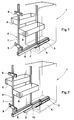
- Fig. 1 the lower part of a cabinet element 1 is shown, in which a simple pull-out device 2 is used.
- This pull-out device 2 is composed of a first rail 3, which is fastened to the bottom 4 of the cabinet element 1, and a second rail 5 slidably mounted therein.
- an installation part 6 is fastened, which in this exemplary embodiment is formed from a rectangular frame 7, can be suspended in or on soft storage compartments 8, which are designed, for example, as wire mesh baskets.
- On the part of the frame 7 forming the front holding elements 9 are attached, to which a front element, not shown, can be attached as a termination for the cabinet element 1.
- the frame 7 is guided by guide means in the upper region of the cabinet element 1.
- the built-in part 6 it is also conceivable to design the built-in part 6 differently, for example as a wooden frame.
- the built-in part 6 can only be pulled out of the cabinet element 1 to a limited extent, since the second rail 5 and the first rail 3 must also overlap by a certain area in the pulled-out state, so that the built-in part 6 also in this extended position is kept stable.
- Fig. 2 shows the same arrangement as shown in Fig. 1 and has been described accordingly, but in addition between the first Rail 3 and the second rail 5 of the pull-out device 2, a rail-shaped intermediate piece 10 is used.
- This intermediate piece 10 makes it possible for the built-in part 6 to be pulled out completely from the cabinet element 1, the accessibility to the storage compartments 8 also being fully guaranteed in the rear area thereof.
- the installation part 6 is held optimally even in the fully extended position.
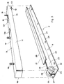
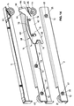
- Fig. 3 shows a simple pull-out device 2, which is composed of a first rail 3 and a second rail 5.
- the second rail 5 is formed from a U-profile 11.
- the second rolling means 12, which consist of a pair of rollers, are arranged in the rear region of this U-profile 11, each roller 13, 14 being rotatably mounted on one leg 15 and 16 of the U-profile 11, respectively.
- Fastening means 18 are attached to the web 17 of the U-profile 11 connecting the two legs 15 and 16, by means of which the installation part (not shown) can be fastened to this second rail 5.
- the front part of the web 17 is bent in such a way that the U-profile 11 is closed when viewed from the front and forms a stop limitation to the rear.
- An adjustable stop 19 which will be described later, is also arranged in the web 17, specifically in the rear area thereof.
- the first rail 3 is composed of two similar U-profiles 20 and 21 of the same type. These two profiles 20 and 21 are placed with their webs 22 and 23 on the back and connected to each other. In each case the two legs 24, 25 and 26, 27 of the two further U-profiles 20 and 21 form a raceway for a respective roller 13 or 14 of the second rail 5.
- the two upper legs 24 and 26 of the two profiles 20 and 21 are separated in the front region of the first rail 3, whereby a recess 28 is created through which the two rollers 13 and 14 of the second rail 5 can be inserted into the corresponding tracks of the first rail 2.
- the first rolling means 29 are attached, which are formed from two rollers 30 and 31, which are each rotatably mounted on a web 22 or 23 of the two profiles 20 and 21.
- the raceway of the second rail 5, which is formed by the underside of the web 17, is supported on these two rollers 30 and 31.
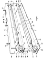
- a rail-shaped intermediate element 10 is inserted between the first rail 3 and the second rail 5 in this fully extendable pull-out device 2.
- This rail-shaped intermediate element 10 is formed from two profiles 32 and 33. These profiles 32 and 33 have a U-shaped basic shape, each consisting of a web 34 and 35 and adjoining legs 36, 37 and 38, 39, respectively. The profiles are put together with the rear sides of the webs 34 and 35 and connected to each other. On the respective lower legs 37 and 39 of the profiles 32 and 33, an additional web 40 and 41 is provided, which is aligned parallel to the corresponding webs 34 and 35, respectively.
- lower rolling means 42 are attached, which are formed from two rollers 43 and 44, which are each rotatably mounted on the corresponding additional web 40 or 41.
- the upper legs 36 and 38 have been separated in their front area, whereby a recess 45 is formed.
- the upper rolling means 46 are arranged, which each consist of a roller 47 and 48, which are rotatably mounted on the webs 34 and 35 of the profiles 32 and 33.
- the rail-shaped intermediate element 10 has an upper raceway, which is formed by the respective inner side of the legs 36 and 37 or 38 and 39.
- the second rolling means 12 of the second rail 5, which can be moved into this position through the recess 45, are guided in this upper track.
- the upper rolling means 46 support the raceway of the second rail 5 formed by the inside of the web 17.
- the lower rolling means 42 can be inserted through the cutout 28 of the first rail 3 into the track formed by the inside of the legs 24 and 25 or 26 and 27, in which they are guided.
- the first rolling means 29 of the first rail 3 support the raceway of the rail-shaped intermediate element 10 formed by the underside of the legs 37 and 39.
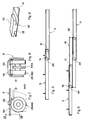
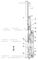
- FIG. 5 shows a simple pull-out device according to FIG. 3 in the assembled state and in the extended position.
- This extended position is limited by the adjustable stop 19, which is used in this constellation in the rear area of the second rail 5.
- the stop 19 abuts the first rolling means 29 of the first rail.
- the inserted position is determined by the bend in the front area of the second rail 5, which likewise abuts the first rolling means 29.
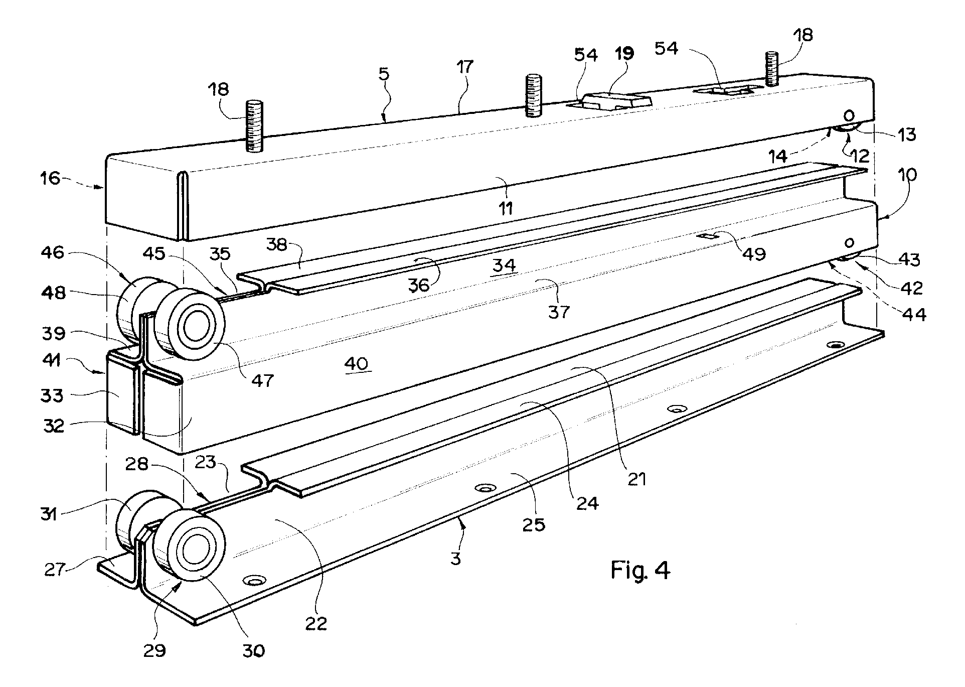
- FIG. 6 shows the fully extendable pull-out device according to FIG. 4 in the assembled state, the extended position being shown.
- the fully extended position of the second rail 5 is in turn determined by the stop 19, which is offset further to the front compared to the position shown in FIG. 5.
- This stop abuts the upper rolling means 46 of the rail-shaped intermediate element 10.
- the rail-shaped intermediate element 10 in turn has a fixed stop 49 on (Fig. 4), which abuts the first rolling means 29 of the first rail 3.
- the inserted position is in turn limited by the bending of the profiles of the second rail 5 and the rail-shaped intermediate element 10 in the respective front area.
- the adjustable stop 19 consists of a plug-in element 50 which has a stop part 51 and a transverse web 52.
- the crosspiece 52 is connected to the stop part 51 via a connecting part 53.
- This plug-in element 50 can now be inserted into a T-shaped recess 54, which is provided in the second rail 5 (FIGS. 3 and 4). After the plug element 50 has been inserted into the T-shaped recess 54, it can be moved in the longitudinal direction, as a result of which the crosspiece 52 is held by the profile. Since, as can be seen from FIGS. 3 and 4, the second rail 5 is equipped with two such recesses 54, which are one behind the other and spaced apart, the stop 19 can be adjusted by repositioning the plug-in element 50.
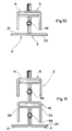
- FIG. 10 shows a cross section through the profiles of a simple pull-out device 2 according to FIGS. 3 and 5.
- the U-profile 11 which forms the second rail 5
- the two further U-profiles 20 and 21, which are the first Form rail 3.
- the two further U-profiles 20 and 21 can be connected to one another, for example, by rivets 55.
- Fig. 11 shows a cross section through a fully extendable pull-out device 2, as shown in Figs. 4 and 6.
- the first rail 3 and the second rail 5 correspond to the illustration in FIG. 10, the rail-shaped intermediate element is achieved by joining the profiles 32 and 33, which can also be connected to one another by rivets 56.
- the width of the pull-out devices 2 has a small dimension, as a result of which pull-out devices 2 of this type can be accommodated in the corresponding cabinet elements without requiring a large amount of space, even if two pull-out devices are used for a built-in part in the lateral areas, the space requirement can be kept low, or that a lateral arrangement of the pull-out part 6 in a cabinet is possible.
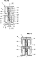
- FIG. 12 shows a view from the front of a second embodiment of a fully extendable pull-out device 2, partly in section.
- the first rail 3, the rail-shaped intermediate element 10 and the second rail 5 can be seen.
- the second rail 5 is practically identical to that of the first embodiment described above.
- the first rail 3 and the rail-shaped intermediate element 10, on the other hand, have a difference, which is that the two profiles 20, 21 of the first rail 3 and the profiles 32, 33 of the rail-shaped intermediate element 10 are each connected in such a way that there is a gap between them 60 arises, which has a width a.
- the rivets 55 and 56 are each provided with a spacer 61, which can have the form of a ring that can be placed on it, or can be designed as a molded-on shoulder on the corresponding rivet.
- the first rolling means 29 visible in this FIG. 12, which are formed by the rollers 30 and 31, and the upper rolling means 46, formed by the rollers 47 and 48, are arranged in the same way as in the previously described first embodiment.
- a control element 62 which will be described later, is inserted into the gap 60 in the rail-shaped intermediate element 10.
- the rail 5 is provided in the rear area with a cam 63 which is arranged such that it can protrude into the gap 60 (FIGS. 12 and 13) of the rail-shaped intermediate piece.
- the control element 62 is mounted, which has the shape of a plate that has a thickness that is slightly smaller than the width a of the gap.
- This control element 62 is pivotable about a pivot axis, which is formed by the rear rivet 56, which serves to connect the two profiles which form the rail-shaped intermediate element 10.
- a recess 65 is made in the rear part 64 of the control element 62 lying behind the pivot axis.
- a control nose 66 is attached in this rear part 64.
- a slot-shaped recess 67 is arranged between the recess 65 and the control nose 66. Since the control element 62 is made of an elastic plastic, the recess and the control lug can spring against one another because of the slot-shaped recess.
- a control surface 69 is formed on top in the front part 68 of the control element 62 lying in front of the pivot axis.
- a slot 70 is let into the control element 62 below this control surface 69. By providing this slot 70, it is achieved that the control surface 69 can deflect resiliently against the slot 70.
- control element 62 is provided in the front part 68 with an opening 75.
- a further rivet 74 projects through this opening 75 and serves to connect the two profiles to form the rail-shaped intermediate element 10. This configuration limits the pivoting movement of the control element 62.
- Another recess 71 is also made in the front part 68 of the control element 62.
- a central rivet 73 is attached in the rail-shaped intermediate element 10 behind the front rivet 56.
- both rivets are each equipped with a spacer sleeve 61. Furthermore, they also have an elastic sleeve 72, which is put over the respective spacer sleeve 61.
- the front and rear rivets 55, with which the profiles for forming the first rail 3 are connected, are also, as already mentioned, provided with spacer sleeves 61, over which an elastic sleeve 72 is also placed.
- the rail-shaped intermediate element 10 cannot move because it is held in place.
- the second rail 5 is first shifted, as shown in FIG. 18.
- the cam 63 of the second rail 5 reaches the control surface 69 of the control element 62.
- the control element 62 is pivoted clockwise, to the extent that it passes through the opening 75 and the further rivet 74 is approved.
- the recess 65 extends from the rivet 55, and the rail-shaped intermediate element 10 is in turn taken along, since the cam 63 is braked by the control surface.
- the rail-shaped intermediate piece 10 then reaches its fully extended position, shown in the center in FIG. 15. In this position, the further recess 71 of the control element 62 is moved onto the front rivet 55 of the first rail 3. This ascent movement is dampened by the elastic cover on the rivet 55.
- the second rail 5 then continues until it has also reached its fully extended position, shown on the right-hand side in FIG. 16. This position is reached when the cam 63 abuts the central rivet 73 of the rail-shaped intermediate element 10. This bumping is also dampened by the elastic casing on the middle rivet 73.
- the rail-shaped intermediate element 10 When moving back into the retracted position of the pull-out device, the rail-shaped intermediate element 10 is carried along by the retracting second rail, since the cam moves onto the control surface 69 of the control element 62, as is shown in FIG. 17. The recess 71 then releases the rivet 55.
- the rail-shaped intermediate piece 10 reaches the inserted end position first, since the cam 63 is still above the control surface 69. The further insertion movement of the second rail 5 is then slightly braked by the control surface 69 on which the cam 63 rests.
- the control nose 66 presses downward, the recess 65 engages in the rear rivet 55.
- the starting situation is reached again, as shown in FIG. 15 (left) and in FIG. 16.
- control element With this arrangement of a control element, a clearly defined sequence of movements is obtained when pulling out as well as when pushing in the pulling device. This results in a more harmonious movement, which is particularly noticeable by a smoother running.
- the braking action of the control surface in cooperation with the cam dampens the possible shocks.
- the control element which is arranged in the gap of the rail-shaped intermediate element and projects into the gap of the first rail, results in improved lateral guidance of the pull-out device, in particular also because of the great length of the control element.
- This embodiment can also be converted from a full extension to a simple extension by removing the rail-shaped intermediate element 10.
- the extended position of the second rail 5 with respect to the first rail 3 can be limited by the cam 63, which runs onto the front rivet 55 of the first rail 3.
Landscapes
- Drawers Of Furniture (AREA)
Abstract
Eine Auszugeinrichtung (2) ermöglicht, einen Einbauteil (6) in einem Schrankelement (1) einschieb- und ausziehbar zu lagern. Die Auszugeinrichtung (2) ist mit einer ersten Schiene (3), welche mit dem Schrankelement (1) verbunden ist, und einer zweiten Schiene (5), welche mit dem Einbauteil (6) verbunden ist, ausgestattet. Die erste Schiene (3) weist erste Rollmittel (29) auf, auf welchen eine Laufbahn der zweiten Schiene (5) abrollt. Die zweite Schiene (5) ist mit zweiten Rollmitteln (12) ausgestattet, welche auf einer Laufbahn der ersten Schiene (3) abrollen. Zwischen die erste Schiene (3) und die zweite Schiene (5) ist ein schienenförmiges Zwischenelement (10) einsetzbar, das mit einer oberen Laufbahn und einer unteren Laufbahn ausgestattet ist, und welches obere Rollmittel (46) und untere Rollmittel (42) aufweist. Dabei wirkt die obere Laufbahn mit den zweiten Rollmitteln (12) der zweiten Schiene (5) zusammen, während die oberen Rollmittel (46) auf der Laufbahn der zweiten Schiene (5) abrollen. Die untere Laufbahn wirkt mit den ersten Rollmitteln (29) der ersten Schiene (3) zusammen, die unteren Rollmittel (42) rollen auf der Laufbahn der ersten Schiene (3) ab. Dadurch können einfache Auszugeinrichtungen problemlos in voll ausziehbare Auszugeinrichtungen umgewandelt werden und umgekehrt.
Description
Die vorliegende Erfindung bezieht sich auf eine Auszugeinrichtung für ein Einbauteil, das in einem Schrankelement einschieb- und ausziehbar ist, gemäss dem Oberbegriff des Patentanspruchs 1.The present invention relates to a pull-out device for a built-in part which can be pushed in and pulled out in a cabinet element, according to the preamble of patent claim 1.
Derartige Auszugeinrichtungen werden insbesondere für eine verschiebbare Lagerung von Einbauteilen verwendet, die schubladenartig in Schränke einschieb- und ausziehbar sind. Diese Einbauteile weisen eine frontseitige Abdeckung auf, die im eingeschobenen Zustand dieses Einbauteils im Schrank die Schrankvorderfläche bildet. Im Innern des verschiebbaren Einbauteils sind Tablare, Behälter, Körbe oder dergleichen regalförmig übereinander angeordnet, welche bei ausgezogenem Einbauteil je von der Seite her zugänglich sind.Such pull-out devices are used in particular for a displaceable mounting of built-in parts which can be inserted and pulled out like drawers in cupboards. These built-in parts have a front cover which, when this built-in part is inserted, forms the front surface of the cupboard in the cupboard. Trays, containers, baskets or the like are arranged one above the other in shelves in the interior of the displaceable built-in part, which are accessible from the side when the built-in part is pulled out.
Die ausziehbaren Einbauteile können beispielsweise aus einem ebenen, rechteckigen Rahmen bestehen, welcher vertikal angeordnet wird und in welchem entsprechende Ablagefächer eingehängt werden können. Die untere Querstrebe dieses Rahmens ist dabei mit der zweiten Schiene der Auszugeinrichtung verbunden, während die obere Querstrebe des Rahmens mit einer Führungseinrichtung versehen ist, welche im Schrank, in welche der Einbauteil einschiebbar ist, befestigt ist. Bei einer derartigen Ausführung des ausziehbaren Einbauteils ist nur eine Auszugeinrichtung erforderlich, welche das gesamte Gewicht des verschiebbaren Einbauteils trägt.The extendable built-in parts can consist, for example, of a flat, rectangular frame which is arranged vertically and in which corresponding storage compartments can be hung. The lower cross strut of this frame is connected to the second rail of the pull-out device, while the upper cross strut of the frame is provided with a guide device which is fastened in the cabinet into which the built-in part can be inserted. With such a design of the extendable installation part, only one pull-out device is required, which carries the entire weight of the displaceable installation part.
Die ausziehbaren Einbauteile können auch aus einem die Form eines Quaders aufweisenden Rahmen bestehen, der jeweils mittels zwei Auszugeinrichtungen gelagert ist, die je in einem seitlichen Bereich dieses Rahmens angeordnet sind.The pull-out built-in parts can also consist of a frame having the shape of a cuboid, which is in each case mounted by means of two pull-out devices which are each arranged in a lateral region of this frame.
Bei einfachen Auszugeinrichtungen ist die ausziehbare zweite Schiene durch Rollmittel in der ersten Schiene, welche am Schrankelement befestigt ist, verschiebbar gelagert. Im voll ausgezogenen Zustand des Einbauteils muss ein Überlappen der beiden Schienen bestehen bleiben, um zu vermeiden, dass die zweite Schiene bezüglich der ersten Schiene abkippen kann, da die zweite Schiene das volle Gewicht des ausziehbaren Einbauteils trägt. Dies bedeutet, dass der verschiebbare Einbauteil nicht vollständig aus dem Schrankelement herausgezogen werden kann, wodurch die seitliche Zugänglichkeit auf den hinteren Bereich des ausziehbaren Einbauteils erschwert ist, da dieser Bereich durch benachbarte Schränke verdeckt wird.In the case of simple pull-out devices, the extendable second rail is displaceably supported by rolling means in the first rail, which is fastened to the cabinet element. When the built-in part is fully extended, the two rails must overlap to avoid that the second rail can tilt with respect to the first rail, since the second rail carries the full weight of the extendable installation part. This means that the displaceable built-in part cannot be pulled out completely from the cabinet element, which makes lateral access to the rear area of the extendable built-in part more difficult, since this area is covered by adjacent cupboards.
Um ein vollständiges Ausziehen des Einbauteils aus dem Schrankelement zu ermöglichen, werden Auszugeinrichtungen verwendet, bei welchen zwischen der ausziehbaren Schiene, die mit dem Einbauteil verbunden ist, und der im Schrankelement befestigten Schiene eine Teleskopschiene eingesetzt ist. Dadurch kann der Einbauteil voll aus dem Schrankelement ausgezogen werden, ein Abkippen wird durch die Teleskopschiene vermieden.In order to enable the built-in part to be pulled out completely from the cupboard element, pull-out devices are used in which a telescopic rail is inserted between the pull-out rail which is connected to the built-in part and the rail fastened in the cupboard element. This allows the built-in part to be fully pulled out of the cabinet element, and the telescopic rail prevents tipping.
Die Aufgabe der Erfindung besteht nun darin, eine einfache Auszugeinrichtung derart zu gestalten, dass sie ohne Abänderungen und ohne grossen Aufwand in einen Vollauszug umwandelbar ist und umgekehrt, wodurch die Produktion vereinfacht werden kann, da weniger unterschiedliche Einzelteile hergestellt werden müssen.The object of the invention is now to design a simple pull-out device in such a way that it can be converted into a full pull-out without changes and with little effort, and vice versa, as a result of which production can be simplified since fewer different individual parts have to be produced.
Erfindungsgemäss erfolgt die Lösung dieser Aufgabe durch die in der Kennzeichnung des Anspruchs 1 angegebenen Merkmale.According to the invention, this object is achieved by the features specified in the characterizing part of claim 1.
Eine vorteilhafte Ausgestaltung der Erfindung besteht darin, dass die zweite Schiene aus einem einfachen U-Profil gebildet ist, wodurch diese Schiene sehr kostengünstig hergestellt werden kann und eine grosse Stabilität aufweist. Die erste Schiene ist aus zwei gleichartigen, miteinander verbundenen weiteren U-Profilen gebildet, wodurch auch diese erste Schiene kostengünstig herstellbar ist und ebenfalls eine hohe Stabilität aufweist. In ähnlicher Weise ist das schienenförmige Zwischenelement ebenfalls aus zwei einfachen Profilen gebildet, die miteinander verbunden sind, wodurch auch dieses schienenförmige Zwischenelement kostengünstig ist und sich ebenfalls durch eine hohe Stabilität auszeichnet.An advantageous embodiment of the invention consists in that the second rail is formed from a simple U-profile, as a result of which this rail can be manufactured very inexpensively and has great stability. The first rail is formed from two similar, interconnected further U-profiles, as a result of which this first rail can also be produced inexpensively and also has high stability. Similarly, the rail-shaped intermediate element is likewise formed from two simple profiles which are connected to one another, as a result of which this rail-shaped intermediate element is also inexpensive and is also distinguished by a high degree of stability.
Die Verbindung der einzelnen Profile zur Herstellung der ersten Schiene und des schienenförmigen Zwischenelementes erfolgt in vorteilhafter Weise durch Vernietung.The individual profiles for producing the first rail and the rail-shaped intermediate element are advantageously connected by riveting.
In vorteilhafter Weise können auf die Nieten zwischen den verbindbaren Profilen Distanzstücke aufgesetzt werden, so dass zwischen den Profilen eine Lücke mit einem bestimmten Abstand entsteht. In die Lücke des Zwischenstücks kann ein Steuerelement eingesetzt werden, mit welchem bewirkt werden kann, dass der Bewegungsablauf des Zwischenstücks und der zweiten Schiene beim Ausziehen und Einschieben des Auszugs beeinflusst werden kann und harmonischer abläuft, was sich durch eine Verbesserung der Laufruhe der Auszugeinrichtung auszeichnet.Advantageously, spacers can be placed on the rivets between the connectable profiles, so that there is a gap between the profiles with a certain distance. A control element can be inserted into the gap of the intermediate piece, which can be used to influence the movement sequence of the intermediate piece and the second rail when pulling out and pushing in the pull-out and to run more smoothly, which is characterized by an improvement in the smooth running of the pull-out device.
Das Steuerelement ist in vorteilhafter Weise plattenförmig gestaltet, wobei dieses auch in die Lücke der ersten Schiene hineinragt. Dadurch erfüllt das Steuerelement noch zusätzlich eine seitliche Führungsfunktion, was zu einer grösseren Stabilität der Auszugeinrichtung führt.The control element is advantageously designed in the form of a plate, which also projects into the gap in the first rail. As a result, the control element additionally fulfills a lateral guiding function, which leads to greater stability of the pull-out device.
Weitere vorteilhafte Ausgestaltungsformen der Erfindung ergeben sich aus den weiteren abhängigen Ansprüchen.Further advantageous embodiments of the invention result from the further dependent claims.
Ausführungsformen der erfindungsgemässen Auszugeinrichtung werden nachfolgend anhand der beiliegenden Zeichnung beispielhaft näher erläutert.Embodiments of the pull-out device according to the invention are explained in more detail below by way of example with reference to the accompanying drawing.
Es zeigt
- Fig. 1 in räumlicher Darstellung eine einfache Auszugeinrichtung im in ein Schrankelement eingesetzten Zustand mit Einbauteil;
- Fig. 2 in räumlicher Darstellung eine voll ausziehbare Auszugeinrichtung im in ein Schrankelement eingesetzten Zustand und aufgesetzten Einbauteil;
- Fig. 3 in räumlicher Darstellung erste Ausführungsform einer einfachen Auszugeinrichtung mit von der ersten Schiene abgehobener zweiter Schiene;
- Fig. 4 in räumlicher Darstellung eine erste Ausführungsform einer voll ausziehbaren Auszugeinrichtung mit von der ersten Schiene abgehobenem schienenförmigen Zwischenelement und zweiter Schiene;
- Fig. 5 eine Schnittdarstellung längs einer einfachen Auszugeinrichtung, im ausgezogenen Zustand;
- Fig. 6 eine Schnittdarstellung einer voll ausziehbaren Auszugeinrichtung im ausgezogenen Zustand;
- Fig. 7 eine Teilansicht eines einstellbaren Anschlags für die zweite Schiene der ersten Ausführungsform, zum Teil geschnitten;
- Fig. 8 eine Schnittdarstellung entlang Linie VIII-VIII gemäss Fig. 7;
- Fig. 9 in räumlicher Darstellung den einstellbaren Anschlag für die zweite Schiene gemäss Fig. 7;
- Fig. 10 eine Darstellung des Querschnitts der ersten Ausführungsform einer einfachen Auszugeinrichtung;
- Fig. 11 eine Darstellung des Querschnitts der ersten Ausführungsform einer voll ausziehbaren Auszugeinrichtung;
- Fig. 12 eine Darstellung einer Ansicht von vorn auf eine zweite Ausführungsform einer voll ausziehbaren Auszugeinrichtung;
- Fig. 13 einen Querschnitt durch die Auszugeinrichtung gemäss Fig. 12;
- Fig. 14 eine Schnittdarstellung entlang Linie XIV - XIV gemäss Fig. 12, wobei das schienenförmige Zwischenstück und die zweite Schiene von der ersten Schiene abgehoben sind;
- Fig. 15 eine Längsschnittdarstellung der zweiten Ausführungsform einer voll ausziehbaren Auszugeinrichtung, die sich in verschiedenen Positionen befindet; und
- Fig. 16 bis Fig. 18 in vergrösserter Darstellung die einzelnen Positionen der voll ausziehbaren Auszugeinrichtung gemäss Fig. 15.
- Figure 1 in a spatial representation of a simple pull-out device in the state inserted in a cabinet element with built-in part.
- Figure 2 in a spatial representation of a fully extendable pull-out device in the state inserted in a cabinet element and fitted part.
- 3 shows a spatial representation of the first embodiment of a simple pull-out device with the second rail lifted off the first rail;
- 4 shows in spatial representation a first embodiment of a fully extendable pull-out device with a rail-shaped intermediate element and second rail lifted off the first rail;
- 5 shows a sectional illustration along a simple pull-out device, in the pulled-out state;
- 6 shows a sectional illustration of a fully extendable pull-out device in the extended state;
- Fig. 7 is a partial view of an adjustable stop for the second rail of the first embodiment, partly in section;
- FIG. 8 shows a sectional illustration along line VIII-VIII according to FIG. 7;
- 9 shows the adjustable stop for the second rail according to FIG. 7 in a spatial representation;
- 10 shows a representation of the cross section of the first embodiment of a simple pull-out device;
- 11 shows a representation of the cross section of the first embodiment of a fully extendable pull-out device;
- 12 shows a front view of a second embodiment of a fully extendable pull-out device;
- 13 shows a cross section through the pull-out device according to FIG. 12;
- 14 shows a sectional illustration along line XIV-XIV according to FIG. 12, the rail-shaped intermediate piece and the second rail being lifted off the first rail;
- 15 shows a longitudinal sectional illustration of the second embodiment of a fully extendable pull-out device which is in different positions; and
- 16 to 18 show an enlarged view of the individual positions of the fully extendable pull-out device according to FIG. 15.
In Fig. 1 ist der untere Teil eines Schrankelementes 1 dargestellt, in welchem eine einfache Auszugeinrichtung 2 eingesetzt ist. Diese Auszugeinrichtung 2 setzt sich aus einer ersten Schiene 3, die am Boden 4 des Schrankelementes 1 befestigt ist, und einer darin verschiebbar gelagerten zweiten Schiene 5 zusammen. Auf der zweiten Schiene 5 ist ein Einbauteil 6 befestigt, der in diesem Ausführungsbeispiel aus einem rechteckförmigen Rahmen 7 gebildet wird, in bzw. an weichem Ablagefächer 8 einhängbar sind, die beispielsweise als Drahtgitterkörbe ausgebildet sind. Am die Frontseite bildenden Teil des Rahmens 7 sind Halteelemente 9 angebracht, an welche ein nicht dargestelltes Frontelement als Abschluss für das Schrankelement 1 befestigt werden kann. In bekannter, nicht dargestellter Weise ist der Rahmen 7 im oberen Bereich des Schrankelementes 1 durch Führungsmittel geführt.In Fig. 1 the lower part of a cabinet element 1 is shown, in which a simple pull-out
Selbstverständlich ist es auch denkbar, den Einbauteil 6 anders auszugestalten, zum Beispiel als Holzgestell.Of course, it is also conceivable to design the built-in
Mit dieser einfachen Auszugeinrichtung 2 kann der Einbauteil 6 nur beschränkt aus dem Schrankelement 1 ausgezogen werden, da die zweite Schiene 5 und die erste Schiene 3 auch im ausgezogenen Zustand um einen bestimmten Bereich überlappend sein müssen, damit der Einbauteil 6 auch in dieser ausgezogenen Lage in stabiler Weise gehalten ist.With this simple pull-out
Fig. 2 zeigt die gleiche Anordnung, wie sie in Fig. 1 dargestellt ist und entsprechend beschrieben wurde, wobei aber zusätzlich zwischen der ersten Schiene 3 und der zweiten Schiene 5 der Auszugeinrichtung 2 ein schienenförmiges Zwischenstück 10 eingesetzt ist. Mit der Verwendung dieses Zwischenstückes 10 wird ermöglicht, dass der Einbauteil 6 vollständig aus dem Schrankelement 1 ausgezogen werden kann, wobei die Zugänglichkeit auf die Ablagefächer 8 auch in deren hinteren Bereich voll gewährleistet ist. Durch die Verwendung des Zwischenstückes 10 ist der Einbauteil 6 auch in voll ausgezogener Position optimal gehalten.Fig. 2 shows the same arrangement as shown in Fig. 1 and has been described accordingly, but in addition between the
Fig. 3 zeigt eine einfache Auszugeinrichtung 2, die aus einer ersten Schiene 3 und einer zweiten Schiene 5 zusammengesetzt ist. Die zweite Schiene 5 ist aus einem U-Profil 11 gebildet. Im hinteren Bereich dieses U-Profils 11 sind die zweiten Rollmittel 12 angeordnet, die aus einem Rollenpaar bestehen, wobei jede Rolle 13, 14 jeweils an einem Schenkel 15 bzw. 16 des U-Profils 11 drehbar gelagert ist.Fig. 3 shows a simple pull-out
An dem die beiden Schenkel 15 und 16 verbindenden Steg 17 des U-Profils 11 sind Befestigungsmittel 18 angebracht, mittels welchen der nicht dargestellte Einbauteil an dieser zweiten Schiene 5 befestigt werden kann. Der vordere Teil des Steges 17 ist derart abgebogen, dass das U-Profil 11 von vorn gesehen abgeschlossen ist, und eine Anschlagbegrenzung nach hinten bildet.Fastening means 18 are attached to the
Ebenfalls im Steg 17, und zwar in dessen hinteren Bereich, ist ein verstellbarer Anschlag 19 angeordnet, der später noch beschrieben wird.An
Die erste Schiene 3 setzt sich aus zwei gleichartigen weiteren U-Profilen 20 und 21 zusammen. Diese beiden Profile 20 und 21 sind mit ihren Stegen 22 und 23 rückseitig aneinandergelegt und miteinander verbunden. Jeweils die beiden Schenkel 24, 25 und 26, 27 der beiden weiteren U-Profile 20 und 21 bilden eine Laufbahn für jeweils eine Rolle 13 bzw. 14 der zweiten Schiene 5.The
Die beiden oberen Schenkel 24 und 26 der beiden Profile 20 und 21 sind im vorderen Bereich der ersten Schiene 3 abgetrennt, wodurch eine Aussparung 28 geschaffen wird, durch welche die beiden Rollen 13 und 14 der zweiten Schiene 5 in die entsprechenden Laufbahnen der ersten Schiene 2 eingeführt werden können.The two
Im vorderen Bereich der Aussparung 28 der ersten Schiene 3 sind die ersten Rollmittel 29 angebracht, die aus zwei Rollen 30 und 31 gebildet sind, die jeweils an einem Steg 22 bzw. 23 der beiden Profile 20 und 21 drehbar gelagert sind. Auf diesen beiden Rollen 30 und 31 ist die Laufbahn der zweiten Schiene 5 abgestützt, die durch die Unterseite des Steges 17 gebildet wird.In the front area of the
In Fig. 4 sind die Bestandteile einer voll ausziehbaren Auszugeinrichtung 2 dargestellt. Die erste Schiene 3 und die zweite Schiene 5 sind identisch mit denjenigen, wie sie in Fig. 3 dargestellt sind und beschrieben wurden, weshalb auf eine detaillierte Beschreibung verzichtet werden kann. Zwischen die erste Schiene 3 und die zweite Schiene 5 ist in dieser voll ausziehbaren Auszugeinrichtung 2 ein schienenförmiges Zwischenelement 10 eingesetzt. Dieses schienenförmige Zwischenelement 10 ist aus zwei Profilen 32 und 33 gebildet. Diese Profile 32 und 33 haben eine U-förmige Grundform, die jeweils durch einen Steg 34 bzw. 35 und daran angrenzenden Schenkeln 36, 37 bzw. 38, 39 bestehen. Die Profile sind jeweils mit den Rückseiten der Stege 34 und 35 aneinandergelegt und miteinander verbunden. An den jeweiligen unteren Schenkeln 37 und 39 der Profile 32 und 33 ist jeweils ein Zusatzsteg 40 bzw. 41 vorgesehen, der jeweils parallel zum entsprechenden Stege 34 bzw. 35 ausgerichtet ist.4 shows the components of a fully extendable pull-out
Im hinteren Bereich des schienenförmigen Zwischenelementes 10 sind untere Rollmittel 42 angebracht, die aus zwei Rollen 43 und 44 gebildet sind, welche jeweils am entsprechenden Zusatzsteg 40 bzw. 41 drehbar gelagert sind.In the rear area of the rail-shaped
Die oberen Schenkel 36 und 38 sind in ihrem vorderen Bereich abgetrennt worden, wodurch eine Aussparung 45 gebildet wird. Im Bereich dieser Aussparung sind die oberen Rollmittel 46 angeordnet, welche jeweils aus einer Rolle 47 und 48 bestehen, die an den Stegen 34 und 35 der Profile 32 und 33 drehbar gelagert sind. Das schienenförmige Zwischenelement 10 verfügt über eine obere Laufbahn, die durch die jeweilige Innenseite der Schenkel 36 und 37 bzw. 38 und 39 gebildet wird. In dieser oberen Laufbahn sind die zweiten Rollmittel 12 der zweiten Schiene 5 geführt, die durch die Aussparung 45 in diese Position eingefahren werden können. Die oberen Rollmittel 46 stützen die durch die Innenseite des Steges 17 gebildete Laufbahn der zweiten Schiene 5 ab.The
Die unteren Rollmittel 42 können durch die Aussparung 28 der ersten Schiene 3 in die durch die Innenseite der Schenkel 24 und 25 bzw. 26 und 27 gebildete Laufbahn eingesetzt werden, in welcher sie geführt werden. Die ersten Rollmittel 29 der ersten Schiene 3 stützen die durch die Unterseite der Schenkel 37 und 39 gebildete Laufbahn des schienenförmigen Zwischenelementes 10 ab.The lower rolling means 42 can be inserted through the
Durch diese Anordnung kann eine voll ausziehbare Auszugeinrichtung 2 erreicht werden, wobei die erste Schiene 3 und die zweite Schiene 5, die ihrerseits eine einfache Auszugeinrichtung 2 (gemäss Fig. 3) bilden können, verwendbar sind.With this arrangement, a fully extendable pull-out
Fig. 5 zeigt eine einfache Auszugeinrichtung gemäss Fig. 3 im zusammengesetzten Zustand und in der ausgezogenen Lage. Diese ausgezogene Lage wird durch den verstellbaren Anschlag 19 begrenzt, der bei dieser Konstellation im hinteren Bereich der zweiten Schiene 5 eingesetzt ist. Der Anschlag 19 stösst hierbei an die ersten Rollmittel 29 der ersten Schiene an. Die eingeschobene Lage wird durch die Abbiegung im vorderen Bereich der zweiten Schiene 5 festgelegt, welche ebenfalls an die ersten Rollmittel 29 anstossen.FIG. 5 shows a simple pull-out device according to FIG. 3 in the assembled state and in the extended position. This extended position is limited by the
Fig. 6 zeigt die voll ausziehbare Auszugeinrichtung gemäss Fig. 4 im zusammengesetzten Zustand, wobei die ausgezogene Position dargestellt ist. Die voll ausgezogene Position der zweiten Schiene 5 wird wiederum durch den Anschlag 19 festgelegt, der hierzu im Vergleich mit der in Fig. 5 dargestellten Position weiter nach vorne versetzt ist. Dieser Anschlag stösst hierbei an die oberen Rollmittel 46 des schienenförmigen Zwischenelementes 10. Das schienenförmige Zwischenelement 10 weist seinerseits einen festen Anschlag 49 auf (Fig. 4), der an die ersten Rollmittel 29 der ersten Schiene 3 anstösst. Die eingeschobene Position wird wiederum durch die Abbiegungen der Profile der zweiten Schiene 5 und des schienenförmigen Zwischenelementes 10 im jeweiligen vorderen Bereich begrenzt.FIG. 6 shows the fully extendable pull-out device according to FIG. 4 in the assembled state, the extended position being shown. The fully extended position of the
Wie aus den Fig. 7 bis 9 ersichtlich ist, besteht der einstellbare Anschlag 19 aus einem Steckelement 50, das einen Anschlagteil 51 und einen Quersteg 52 aufweist. Der Quersteg 52 ist über ein Verbindungsteil 53 mit dem Anschlagteil 51 verbunden. Dieses Steckelement 50 lässt sich nun in eine T-förmige Ausnehmung 54, die in der zweiten Schiene 5 (Fig. 3 und 4) angebracht ist, einstecken. Nach dem Einstecken des Steckelementes 50 in die T-förmige Ausnehmung 54 kann dieses in Längsrichtung verschoben werden, wodurch der Quersteg 52 durch das Profil gehalten wird. Da, wie aus den Fig. 3 und 4 ersichtlich ist, die zweite Schiene 5 mit zwei derartigen Ausnehmungen 54 ausgestattet ist, die hintereinander und voneinander beabstandet sind, kann der Anschlag 19 durch Umstecken des Steckelementes 50 eingestellt werden.As can be seen from FIGS. 7 to 9, the
Fig. 10 zeigt einen Querschnitt durch die Profile einer einfachen Auszugeinrichtung 2 gemäss Fig. 3 und 5. Hierbei ist das U-Profil 11 ersichtlich, welches die zweite Schiene 5 bildet, sowie die beiden weiteren U-Profile 20 und 21, die die erste Schiene 3 bilden. Die beiden weiteren U-Profile 20 und 21 können beispielsweise durch Nieten 55 miteinander verbunden sein.FIG. 10 shows a cross section through the profiles of a simple pull-out
Fig. 11 zeigt einen Querschnitt durch eine voll ausziehbare Auszugeinrichtung 2, wie sie in den Fig. 4 und 6 dargestellt ist. Die erste Schiene 3 und die zweite Schiene 5 entsprechen der Darstellung in Fig. 10, das schienenförmige Zwischenelement wird durch Zusammenfügen der Profile 32 und 33 erreicht, die ebenfalls durch Nieten 56 miteinander verbunden werden können.Fig. 11 shows a cross section through a fully extendable pull-out
Durch den Aufbau der erfindungsgemässen Auszugeinrichtung mittels einfacher Profile kann eine kostengünstige Herstellung erreicht werden. Zudem ergibt sich eine grosse Stabilität. Die Breite der Auszugeinrichtungen 2 weist eine geringe Dimension auf, dadurch können derartige Auszugeinrichtungen 2 ohne grossen Platzbedarf in den entsprechenden Schrankelementen untergebracht werden, wobei auch bei Verwendung von zwei Auszugeinrichtungen für einen Einbauteil in dessen seitlichen Bereichen der Platzbedarf gering gehalten werden kann, oder dass eine seitliche Anordnung des Auszugteils 6 in einem Schrank möglich wird.By constructing the pull-out device according to the invention by means of simple profiles, inexpensive production can be achieved. In addition, there is great stability. The width of the pull-out
Fig. 12 zeigt eine Ansicht von vorn auf eine zweite Ausführungsform einer voll ausziehbaren Auszugeinrichtung 2, zum Teil geschnitten. Hierbei ist die erste Schiene 3, das schienenförmige Zwischenelement 10 und die zweite Schiene 5 ersichtlich. Die zweite Schiene 5 ist praktisch identisch wie diejenige der vorgängig beschriebenen ersten Ausführungsform. Die erste Schiene 3 und das schienenförmige Zwischenelement 10 weisen hingegen einen Unterschied auf, der darin besteht, dass die zwei Profile 20, 21 der ersten Schiene 3 und die Profile 32, 33 des schienenförmigen Zwischenelements 10 jeweils derart miteinander verbunden sind, dass dazwischen eine Lücke 60 entsteht, die eine Breite a aufweist. Dies wird dadurch erreicht, dass die Nieten 55 und 56 jeweils mit einem Distanzstück 61 versehen sind, die die Form eines aufsetzbaren Ringes haben können, oder als angeformte Absetzung am entsprechenden Niet ausgebildet sein können. Die in dieser Fig. 12 sichtbaren ersten Rollmittel 29, die durch die Rollen 30 und 31 gebildet sind, und die oberen Rollmittel 46, gebildet durch die Rollen 47 und 48, sind gleich angeordnet, wie in der vorgängig beschriebenen ersten Ausführungsform.12 shows a view from the front of a second embodiment of a fully extendable pull-out
In der Schnittdarstellung gemäss Fig. 13 sind wiederum die erste Schiene 3, die zweite Schiene 5 und das dazwischen angeordnete schienenförmige Zwischenelement 10 sowie die zweiten Rollmittel 12, gebildet durch die Rollen 13 und 14 und die unteren Rollmittel 42, gebildet durch die Rollen 43 und 44, ersichtlich.13 are again the
Wie den Fig. 12 und 13 entnehmbar ist, ist in die Lücke 60 im schienenförmigen Zwischenelement 10 ein Steuerelement 62 eingesetzt, das später noch beschrieben wird.As can be seen from FIGS. 12 and 13, a
Die Schiene 5 ist, wie in Fig. 14 dargestellt ist, im hinteren Bereich mit einem Nocken 63 versehen, der so angeordnet ist, dass er in die Lücke 60 (Fig. 12 und 13) des schienenförmigen Zwischenstückes hineinragen kann.As shown in FIG. 14, the
Im schienenförmigen Zwischenstück 10 ist das Steuerelement 62 angebracht, das die Form einer Platte hat, die eine Dicke aufweist, die geringfügig kleiner ist als die Breite a der Lücke. Dieses Steuerelement 62 ist um eine Schwenkachse schwenkbar, die durch den hinteren Niet 56 gebildet wird, der zur Verbindung der beiden Profile dient, die das schienenförmige Zwischenelement 10 bilden. Im hinter der Schwenkachse liegenden hinteren Teil 64 des Steuerelementes 62 ist eine Ausnehmung 65 angebracht. Des weiteren ist in diesem hinteren Teil 64 eine Steuernase 66 angebracht. Zwischen der Ausnehmung 65 und der Steuernase 66 ist eine schlitzförmige Aussparung 67 angeordnet. Da das Steuerelement 62 aus einem elastischen Kunststoff gefertigt ist, können die Aussparung und die Steuernase wegen der schlitzförmigen Aussparung gegeneinander federn.In the rail-shaped
Im vor der Schwenkachse liegenden vorderen Teil 68 des Steuerelementes 62 ist obenliegend eine Steuerfläche 69 angeformt. Unterhalb dieser Steuerfläche 69 ist ein Schlitz 70 in das Steuerelement 62 eingelassen. Durch das Anbringen dieses Schlitzes 70 wird erreicht, dass die Steuerfläche 69 federnd gegen den Schiitz 70 hin ausweichen kann.A
Des weiteren ist das Steuerelement 62 im vorderen Teil 68 mit einer Öffnung 75 ausgestattet. Durch diese Öffnung 75 ragt ein weiterer Niet 74, der zur Verbindung der beiden Profile zur Bildung des schienenförmigen Zwischenelement 10 dient. Durch diese Ausgestaltung wird die Schwenkbewegung des Steuerelementes 62 begrenzt.Furthermore, the
Ebenfalls im vorderen Teil 68 des Steuerelementes 62 ist eine weitere Ausnehmung 71 angebracht.Another
Im schienenförmigen Zwischenelement 10 ist hinter dem vorderen Niet 56 ein mittlerer Niet 73 angebracht. Beide Nieten sind, wie bereits beschrieben worden ist, jeweils mit einer Distanzhülse 61 ausgestattet. Des weiteren verfügen sie noch über eine elastische Hülle 72, die über die jeweilige Distanzhülse 61 gestülpt ist.A
Der vordere und hintere Niet 55, mit welchen die Profile zur Bildung der ersten Schiene 3 verbunden sind, sind ebenfalls, wie bereits erwähnt, mit Distanzhülsen 61 versehen, über welche ebenfalls jeweils eine elastische Hülle 72 gestülpt ist.The front and
Die Funktionsweise dieses Steuerelementes 62 wird nun nachfolgend anhand der Fig. 15 und 16 bis 18 erläutert. In Fig. 15 ist linksseitig die Situation dargestellt, wenn sich die Auszugeinrichtung in der voll eingefahrenen Position befindet. Dies entspricht auch der Darstellung gemäss Fig. 16. Die zweite Schiene 5 drückt die Steuernase 66 nach unten, die Ausnehmung 65 ist in den hinteren Niet 55 eingeklinkt.The operation of this
Beim Ausziehen der Auszugeinrichtung kann sich somit das schienenförmige Zwischenelement 10 nicht verschieben, da dieses festgehalten wird. Somit wird zuerst die zweite Schiene 5 verschoben, wie dies in der Fig. 18 dargestellt ist. Der Nocken 63 der zweiten Schiene 5 gelangt auf die Steuerfläche 69 des Steuerelementes 62. Sobald die durch den Niet 56 gebildete Schwenkachse durch den Nocken 63 überfahren ist, wird das Steuerelement 62 im Uhrzeigersinn verschwenkt, und zwar soweit, wie es durch die Öffnung 75 und den weiteren Niet 74 zugelassen wird. Dadurch fährt die Ausnehmung 65 aus dem Niet 55 aus, das schienenförmige Zwischenelement 10 wird nun seinerseits mitgenommen, da der Nocken 63 durch die Steuerfläche gebremst wird.When the pull-out device is pulled out, the rail-shaped
Das schienenförmige Zwischenstück 10 erreicht dann seine voll ausgefahrene Position, dargestellt in der Mitte in Fig. 15. In dieser Position ist die weitere Ausnehmung 71 des Steuerelementes 62 auf den vorderen Niet 55 der ersten Schiene 3 aufgefahren. Diese Auffahrbewegung wird durch die elastische Hülle auf dem Niet 55 gedämpft.The rail-shaped
Die zweite Schiene 5 fährt dann weiter, bis sie ebenfalls ihre voll ausgezogene Lage erreicht hat, dargestellt auf der rechten Seite in Fig. 16. Diese Lage ist dann erreicht, wenn der Nocken 63 am mittleren Niet 73 des schienenförmigen Zwischenelementes 10 anstösst. Auch dieses Anstossen wird durch die elastische Hülle auf dem mittleren Niet 73 gedämpft.The
Beim Zurückfahren in die eingeschobene Position der Auszugeinrichtung wird das schienenförmige Zwischenelement 10 durch die zurückfahrende zweite Schiene mitgenommen, da der Nocken auf die Steuerfläche 69 des Steuerelementes 62 auffährt, wie dies in Fig. 17 dargestellt ist. Danach gibt die Ausnehmung 71 den Niet 55 frei. Das schienenförmige Zwischenstück 10 erreicht die eingeschobene Endlage zuerst, da sich der Nocken 63 immer noch über der Steuerfläche 69 befindet. Die weitere Einschiebbewegung der zweiten Schiene 5 wird dann durch die Steuerfläche 69, an der der Nocken 63 anliegt, leicht gebremst. Beim Erreichen der eingeschobenen Endlage der zweiten Schiene 5 drückt diese die Steuernase 66 nach unten, die Ausnehmung 65 greift in den hinteren Niet 55 ein. Dadurch ist wieder die Ausgangssituation erreicht, wie sie in Fig. 15 (links) und in Fig. 16 dargestellt ist.When moving back into the retracted position of the pull-out device, the rail-shaped
Es wäre denkbar, dass beim Einschieben der Auszugvorrichtung aus irgend einem Grund die zweite Schiene 5 über die Steuernase 66 fährt, bevor das schienenförmige Zwischenelement 10 seine hintere Endlage erreicht hat. Somit würde der hintere Teil 64 des Steuerelementes 62 nach unten gedrückt, ohne dass die Ausnehmung 65 in den hinteren Niet 55 eingegriffen hat. Trotzdem könnte die vollständig eingeschobene Position erreicht werden, da der Bereich mit der Ausnehmung 65 wegen der schlitzförmigen Aussparung 67 hochfedern könnte, so dass die Ausnehmung 65 trotzdem in den hinteren Niet 55 einschnappen könnte.It would be conceivable that when the pull-out device is pushed in, the
Mit dieser Anordnung eines Steuerelementes erhält man einen klar definierten Bewegungsablauf beim Ausziehen wie auch beim Einschieben der Auszugvorrichtung. Dadurch erhält man eine harmonischere Bewegung, was sich insbesondere durch eine grössere Laufruhe bemerkbar macht. Durch die abbremsende Wirkung der Steuerfläche im Zusammenwirken mit dem Nocken werden die möglichen Schläge gedämpft. Durch das Steuerelement, das in der Lücke des schienenförmigen Zwischenelementes angeordnet ist und in die Lücke der ersten Schiene hineinragt, wird insbesondere auch wegen der grossen Länge des Steuerelementes eine verbesserte seitliche Führung der Auszugvorrichtung erhalten.With this arrangement of a control element, a clearly defined sequence of movements is obtained when pulling out as well as when pushing in the pulling device. This results in a more harmonious movement, which is particularly noticeable by a smoother running. The braking action of the control surface in cooperation with the cam dampens the possible shocks. The control element, which is arranged in the gap of the rail-shaped intermediate element and projects into the gap of the first rail, results in improved lateral guidance of the pull-out device, in particular also because of the great length of the control element.
Diese Ausführungsform kann auch von einem Vollauszug in einen einfachen Auszug umgerüstet werden, indem das schienenförmige Zwischenelement 10 herausgenommen wird. Die ausgezogene Lage der zweiten Schiene 5 bezüglich der ersten Schiene 3 kann durch den Nocken 63, der auf den vorderen Niet 55 der ersten Schiene 3 auffährt, begrenzt werden.This embodiment can also be converted from a full extension to a simple extension by removing the rail-shaped
Claims (15)
Priority Applications (1)
| Application Number | Priority Date | Filing Date | Title |
|---|---|---|---|
| TW088221602U TW411800U (en) | 1997-05-02 | 1997-11-06 | Pull-out mechanism for a built-in part to be pushed into and pulled out of a cupboard element |
Applications Claiming Priority (2)
| Application Number | Priority Date | Filing Date | Title |
|---|---|---|---|
| CH133396 | 1996-05-28 | ||
| CH1333/96 | 1996-05-28 |
Publications (2)
| Publication Number | Publication Date |
|---|---|
| EP0809956A2 true EP0809956A2 (en) | 1997-12-03 |
| EP0809956A3 EP0809956A3 (en) | 1997-12-10 |
Family
ID=4208023
Family Applications (1)
| Application Number | Title | Priority Date | Filing Date |
|---|---|---|---|
| EP97810277A Withdrawn EP0809956A3 (en) | 1996-05-28 | 1997-05-02 | Drawer device for a slidable, flush-mounted element incorporated in a cupboard unit |
Country Status (1)
| Country | Link |
|---|---|
| EP (1) | EP0809956A3 (en) |
Cited By (8)
| Publication number | Priority date | Publication date | Assignee | Title |
|---|---|---|---|---|
| AT410165B (en) * | 1999-10-18 | 2003-02-25 | Fulterer Gmbh | EXTENSION DEVICE AND CARAVAN OR MOTORHOME WITH EXTENDABLE SIDE PANELS |
| EP1647206A2 (en) | 2004-10-14 | 2006-04-19 | Paul Hettich GmbH & Co. KG | Telescoping slide for a pull-out furniture part |
| WO2007000785A1 (en) * | 2005-06-28 | 2007-01-04 | Compagnucci Holding S.P.A. | Improved frame to support pull-out and rotating racks for cabinets- |
| WO2007036971A1 (en) * | 2005-09-30 | 2007-04-05 | Compagnucci Holding S.P.A. | Built-in sliding rotating element for modular corner cabinets |
| DE202008009313U1 (en) * | 2008-07-11 | 2009-11-26 | Paul Hettich Gmbh & Co. Kg | Ejection device of a pull-out system |
| EP2526823A1 (en) * | 2011-05-24 | 2012-11-28 | Peka-Metall AG | Cabinet with pull-out frame |
| CN104203049A (en) * | 2012-03-20 | 2014-12-10 | 尤利乌斯·布卢姆有限公司 | Furniture pull-out |
| DE202019104414U1 (en) * | 2019-08-09 | 2020-11-10 | Werner Hülsmann | Pull-out system for especially mobile homes |
Family Cites Families (4)
| Publication number | Priority date | Publication date | Assignee | Title |
|---|---|---|---|---|
| FR2148973A5 (en) * | 1971-08-02 | 1973-03-23 | Rey Grange Marius | |
| FR2372608A2 (en) * | 1971-08-02 | 1978-06-30 | Herger Sa | Roller gear for bin of pharmaceutical cabinet - is arm of three intersliding lengths with roller bearings |
| FR2149645A5 (en) * | 1971-08-18 | 1973-03-30 | Sauvageot Georges | |
| DE4224281A1 (en) * | 1992-07-23 | 1994-01-27 | Krause Robert Gmbh Co Kg | Support for cupboard pull out compartments - has carcass rail, pull out rail and telescopic rail, with rollers |
-
1997
- 1997-05-02 EP EP97810277A patent/EP0809956A3/en not_active Withdrawn
Cited By (12)
| Publication number | Priority date | Publication date | Assignee | Title |
|---|---|---|---|---|
| AT410165B (en) * | 1999-10-18 | 2003-02-25 | Fulterer Gmbh | EXTENSION DEVICE AND CARAVAN OR MOTORHOME WITH EXTENDABLE SIDE PANELS |
| EP1647206A2 (en) | 2004-10-14 | 2006-04-19 | Paul Hettich GmbH & Co. KG | Telescoping slide for a pull-out furniture part |
| EP1647206A3 (en) * | 2004-10-14 | 2012-02-15 | Paul Hettich GmbH & Co. KG | Telescoping slide for a pull-out furniture part |
| WO2007000785A1 (en) * | 2005-06-28 | 2007-01-04 | Compagnucci Holding S.P.A. | Improved frame to support pull-out and rotating racks for cabinets- |
| CN101208028B (en) * | 2005-06-28 | 2010-06-16 | 孔帕纽奇控股有限公司 | Modified frame supporting pull-out swivel shelves for cabinets |
| WO2007036971A1 (en) * | 2005-09-30 | 2007-04-05 | Compagnucci Holding S.P.A. | Built-in sliding rotating element for modular corner cabinets |
| US8083303B2 (en) * | 2005-09-30 | 2011-12-27 | Rossano Compagnucci | Built-in sliding rotating element for modular corner cabinets |
| DE202008009313U1 (en) * | 2008-07-11 | 2009-11-26 | Paul Hettich Gmbh & Co. Kg | Ejection device of a pull-out system |
| DE102009026136B4 (en) * | 2008-07-11 | 2018-02-22 | Paul Hettich Gmbh & Co. Kg | Ejection device of a pull-out system |
| EP2526823A1 (en) * | 2011-05-24 | 2012-11-28 | Peka-Metall AG | Cabinet with pull-out frame |
| CN104203049A (en) * | 2012-03-20 | 2014-12-10 | 尤利乌斯·布卢姆有限公司 | Furniture pull-out |
| DE202019104414U1 (en) * | 2019-08-09 | 2020-11-10 | Werner Hülsmann | Pull-out system for especially mobile homes |
Also Published As
| Publication number | Publication date |
|---|---|
| EP0809956A3 (en) | 1997-12-10 |
Similar Documents
| Publication | Publication Date | Title |
|---|---|---|
| AT401334B (en) | LOCKING DEVICE FOR DRAWERS | |
| EP0525153A1 (en) | Sliding guide-rail system for drawers. | |
| EP0545329A2 (en) | Drawer slide fitting | |
| DE2846764C2 (en) | Pull-out guide for drawers or the like. | |
| EP0957714B1 (en) | Flush-mounted extraction guide for drawers etc. | |
| EP0790022A2 (en) | Slide for drawers placed under the drawer bottom | |
| EP2526824B1 (en) | Pull-out guide for front cover | |
| DE9003313U1 (en) | Fastening and/or holding device for roller strips on support rails or similar, in particular of flow racks | |
| DE3923776C2 (en) | ||
| EP0809956A2 (en) | Drawer device for a slidable, flush-mounted element incorporated in a cupboard unit | |
| DE29616756U1 (en) | Full extension fitting | |
| DE4028877A1 (en) | Drawer system | |
| AT413186B (en) | UNDERFLOOR EXTRACTION FOR EXTENDABLE FURNITURE PARTS | |
| EP0855487B1 (en) | Guiding device for a sliding door | |
| EP2520197B1 (en) | Pull-out guide for front cover | |
| AT312851B (en) | Pull-out with unwinding bodies, preferably with rollers, for pull-out furniture parts | |
| AT390359B (en) | DRAWER EXTENSION AS A SIMPLE EXTENSION | |
| EP1449460B1 (en) | Pull-out rail, in particular for kitchen furniture | |
| AT390721B (en) | Drawer runner | |
| DE3246915A1 (en) | Telescopic pull-out guide for drawers and the like | |
| EP1721547B1 (en) | Lateral guide for a pull-out element of a vertical drawer | |
| DE20321394U1 (en) | Drawer rail system comprises two rails attached to carcass, rails attached to drawer bottom and intermediate rails with roller at its front end, two rollers one above the other at its center and one roller at its rear end | |
| DE19633241B4 (en) | Underfloor pull-out guide for drawers etc. | |
| AT406109B (en) | EXTENSION GUIDE SET FOR DRAWERS | |
| DE2614810A1 (en) | Retainer and guide for furniture sliding doors - has vertical shafts for guide rollers and adjusting retainer bracket |
Legal Events
| Date | Code | Title | Description |
|---|---|---|---|
| PUAI | Public reference made under article 153(3) epc to a published international application that has entered the european phase |
Free format text: ORIGINAL CODE: 0009012 |
|
| PUAL | Search report despatched |
Free format text: ORIGINAL CODE: 0009013 |
|
| AK | Designated contracting states |
Kind code of ref document: A2 Designated state(s): AT CH DE ES FR GB IT LI |
|
| AX | Request for extension of the european patent |
Free format text: AL;LT;LV;RO;SI |
|
| AK | Designated contracting states |
Kind code of ref document: A3 Designated state(s): AT CH DE ES FR GB IT LI |
|
| AX | Request for extension of the european patent |
Free format text: AL;LT;LV;RO;SI |
|
| 17P | Request for examination filed |
Effective date: 19980112 |
|
| 17Q | First examination report despatched |
Effective date: 19990624 |
|
| GRAG | Despatch of communication of intention to grant |
Free format text: ORIGINAL CODE: EPIDOS AGRA |
|
| GRAG | Despatch of communication of intention to grant |
Free format text: ORIGINAL CODE: EPIDOS AGRA |
|
| GRAH | Despatch of communication of intention to grant a patent |
Free format text: ORIGINAL CODE: EPIDOS IGRA |
|
| DAX | Request for extension of the european patent (deleted) | ||
| GRAH | Despatch of communication of intention to grant a patent |
Free format text: ORIGINAL CODE: EPIDOS IGRA |
|
| STAA | Information on the status of an ep patent application or granted ep patent |
Free format text: STATUS: THE APPLICATION IS DEEMED TO BE WITHDRAWN |
|
| 18D | Application deemed to be withdrawn |
Effective date: 20011201 |