EP0216612A2 - Schiefscheibenverdichter - Google Patents
Schiefscheibenverdichter Download PDFInfo
- Publication number
- EP0216612A2 EP0216612A2 EP86307224A EP86307224A EP0216612A2 EP 0216612 A2 EP0216612 A2 EP 0216612A2 EP 86307224 A EP86307224 A EP 86307224A EP 86307224 A EP86307224 A EP 86307224A EP 0216612 A2 EP0216612 A2 EP 0216612A2
- Authority
- EP
- European Patent Office
- Prior art keywords
- wobble plate
- plate
- guide
- compressor
- shoes
- Prior art date
- Legal status (The legal status is an assumption and is not a legal conclusion. Google has not performed a legal analysis and makes no representation as to the accuracy of the status listed.)
- Granted
Links
- 230000002265 prevention Effects 0.000 claims description 26
- 230000002093 peripheral effect Effects 0.000 claims description 4
- 238000010276 construction Methods 0.000 description 4
- 230000002159 abnormal effect Effects 0.000 description 2
- 238000005299 abrasion Methods 0.000 description 2
- 230000004048 modification Effects 0.000 description 2
- 238000012986 modification Methods 0.000 description 2
- 230000004323 axial length Effects 0.000 description 1
Images

Classifications
-
- F—MECHANICAL ENGINEERING; LIGHTING; HEATING; WEAPONS; BLASTING
- F04—POSITIVE - DISPLACEMENT MACHINES FOR LIQUIDS; PUMPS FOR LIQUIDS OR ELASTIC FLUIDS
- F04B—POSITIVE-DISPLACEMENT MACHINES FOR LIQUIDS; PUMPS
- F04B25/00—Multi-stage pumps
- F04B25/04—Multi-stage pumps having cylinders coaxial with, or parallel or inclined to, main shaft axis
-
- F—MECHANICAL ENGINEERING; LIGHTING; HEATING; WEAPONS; BLASTING
- F04—POSITIVE - DISPLACEMENT MACHINES FOR LIQUIDS; PUMPS FOR LIQUIDS OR ELASTIC FLUIDS
- F04B—POSITIVE-DISPLACEMENT MACHINES FOR LIQUIDS; PUMPS
- F04B27/00—Multi-cylinder pumps specially adapted for elastic fluids and characterised by number or arrangement of cylinders
- F04B27/08—Multi-cylinder pumps specially adapted for elastic fluids and characterised by number or arrangement of cylinders having cylinders coaxial with, or parallel or inclined to, main shaft axis
- F04B27/10—Multi-cylinder pumps specially adapted for elastic fluids and characterised by number or arrangement of cylinders having cylinders coaxial with, or parallel or inclined to, main shaft axis having stationary cylinders
- F04B27/1036—Component parts, details, e.g. sealings, lubrication
- F04B27/1054—Actuating elements
-
- F—MECHANICAL ENGINEERING; LIGHTING; HEATING; WEAPONS; BLASTING
- F04—POSITIVE - DISPLACEMENT MACHINES FOR LIQUIDS; PUMPS FOR LIQUIDS OR ELASTIC FLUIDS
- F04B—POSITIVE-DISPLACEMENT MACHINES FOR LIQUIDS; PUMPS
- F04B27/00—Multi-cylinder pumps specially adapted for elastic fluids and characterised by number or arrangement of cylinders
- F04B27/08—Multi-cylinder pumps specially adapted for elastic fluids and characterised by number or arrangement of cylinders having cylinders coaxial with, or parallel or inclined to, main shaft axis
-
- Y—GENERAL TAGGING OF NEW TECHNOLOGICAL DEVELOPMENTS; GENERAL TAGGING OF CROSS-SECTIONAL TECHNOLOGIES SPANNING OVER SEVERAL SECTIONS OF THE IPC; TECHNICAL SUBJECTS COVERED BY FORMER USPC CROSS-REFERENCE ART COLLECTIONS [XRACs] AND DIGESTS
- Y10—TECHNICAL SUBJECTS COVERED BY FORMER USPC
- Y10T—TECHNICAL SUBJECTS COVERED BY FORMER US CLASSIFICATION
- Y10T74/00—Machine element or mechanism
- Y10T74/18—Mechanical movements
- Y10T74/18056—Rotary to or from reciprocating or oscillating
- Y10T74/18296—Cam and slide
- Y10T74/18336—Wabbler type
Definitions
- This invention relates to wobble plate type compressors with a rotation prevention mechanism for the wobble plate.
- the rotation of a drive shaft is converted into reciprocating motion through a cam rotor having an inclined end surface, the cam rotor being mounted on an end of the drive shaft and the wobble plate being disposed on the inclined end surface with a needle bearing therebetween.
- the wobble plate is prevented from rotating and is instead nutated, or made to wobble. Therefore, the wobble plate type compressor is generally provided with a rotation prevention mechanism for the wobble plate.
- US-A-4073603 and US-A-4415163 disclose one type of rotation prevention mechanism for the wobble plate.
- a ball member projects radially outwards from the wobble plate and is trapped between a pair of pads or slippers movable in a groove formed between opposed plate members located near the lower portion of the compressor housing.
- the wobble plate is able to rotate about two axes, but is prevented from rotating relative to the compressor housing. Therefore, the rotation prevention force acts on the ball member of the rotation prevention mechanism, and it is transferred to the wobble plate through a pin on which the ball member is mounted.
- the wobble plate and the pin are also acted on by the large force and the pin/ball member must be made strong enough to withstand this force.
- One way to increase the strength of the pin/ball member is to lengthen the pin, but this may result in the wobble plate being weakened.
- a guide slider 1 is provided with a slot 11 at one end and is disposed on an outer peripheral surface of a wobble plate 2 so as to project radially outwards.
- a flat guide plate 3 is positioned in the bottom portion of a crank chamber of the compressor and is aligned with the axial direction of the compressor. The slot 11 of the slider receives the guide plate 3 to prevent the unwanted rotation of the wobble plate 2.
- the type of contact between the slider 1 and the plate 3 is generally face contact. However, line contact between the slider 1 and the plate 3 may occur owing to incorrect assembly of the slider 1. Furthermore, the size of the contact area changes as the compressor operates. Therefore, abnormal wearing or abrasion results and the rotation prevention torque is unevenly transmitted via the contact area from the plate to the slider, thereby reducing the durability of the rotation prevention mechanism.
- US-A-4297085 discloses a modification of the above rotation prevention mechanism.
- a guide rod replaces the guide plate and a spherical element is disposed between the slot of the guide slider and the guide rod to eliminate contact difficulties.
- this rotation prevention mechanism has a large number of elements and is complicated to assemble.
- a wobble plate type compressor comprises a compressor housing containing a cylinder block having a plurality of cylinders formed therein; a plurality of pistons slidably fitted into respective ones of the cylinders; a drive shaft; a cam rotor mounted on the drive shaft and having an inclined end surface; a wobble plate rotatably mounted on the inclined end surface and prevented from rotating relative to the compressor housing by a rotation prevention mechanism which includes an elongate guide plate attached to the compressor housing adjacent to the periphery of the wobble plate and arranged to extend parallel to the centre line of the drive shaft and a slot formed in the outer peripheral surface of the wobble plate with the guide plate slidably located therein; and piston rods connecting respecting ones of the pistons to the wobble plate, and is characterized in that the rotation prevention mechanism further comprises a spherically-curved concave surface formed in each of the opposed side surfaces of the slot and two shoes, each shoe having a spherically-curved convex surface which is
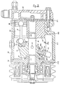
- the compressor comprises a compressor housing 20 having a cylinder block 201 fixed therein at a rear end thereof, a front end plate 21 disposed on a front end opening of the compressor housing 20 and a cylinder head 22, which has a discharge chamber and a suction chamber, disposed on a rear end opening of the compressor housing 20 with a valve plate 221 therebetween.
- the compressor housing 20 contains a crank chamber 23 adjacent to the cylinder block 201, and the cylinder block 201 is provided with a plurality of equiangularly spaced cylinders 24.
- a drive shaft 25 has one end rotatably mounted in the cylinder block 201 through a bearing 242 and the other end rotatably mounted in the front end plate 21 through a bearing 211.
- a cam rotor 26 is fixed to the drive shaft 25 by a pin 27 and is rotatably supported by the inner end surface of the front end plate 21 through a thrust bearing 28.
- a wobble plate 29 is disposed around the outer surface of a reduced diameter portion 261 of the cam rotor 26. The portion 261 projects outwards from an inclined surface of the cam rotor 26, which supports the wobble plate 29 through a thrust bearing 30. The wobble plate 29 is prevented from moving axially by a clip 31.
- Pistons 32 are reciprocatably disposed in each of the cylinders 24 and connected to the wobble plate 29 through respective piston rods 33.
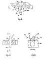
- the rotation prevention mechanism 34 includes a slot 341 formed in the outer peripheral surface of the wobble plate 29 and a flat guide plate 342 rigidly attached to the bottom portion of the crank chamber 23.
- the slot 341 extends from a front surface 29a to a rear surface 29b of the wobble plate 29 and contains two opposed spherically-curved concave surfaces 343, 344 which have a common centre of curvature.
- a shoe 345, 346 having a flat guide surface and a spherically-curved convex surface is received in each of the concave surfaces 343, 344 with the guide surfaces of the shoes 345, 346 defining a gap having a width a little larger than the thickness of the flat plate 342.
- the flat plate 342 extends in the axial direction of the compressor and is supported by the front end plate 21 at location 212 and the housing 20 at location 243.
- the radially innermost surface 342a of the flat plate 342 is curved so as not to come into contact with the outer surface of the wobble plate 29 during movement of the wobble plate 29.
- the axial length of the flat plate 342 is greater than the range of movement of the wobble plate 29.
- the spherically-curved surfaces of the shoes 345, 346 are able to slide over the spherically-curved concave surfaces 343, 344 and the guide surfaces of the shoes slidably receive the flat plate 342 therebetween.
- the cam rotor 26 when a driving force is transmitted from an external driving source to the drive shaft 25, the cam rotor 26 is rotated together with the drive shaft 25.
- the wobble plate 29 is prevented from rotating relative to the compressor housing 20 by the rotation prevention mechanism 34, but it is permitted to slide over and rotate relative to the flat plate 342 owing to the shoes 345, 346 being able both to slide along the opposite faces of the flat plate 342 and to rotate in the slot 341. Therefore, the pistons may be reciprocated within their cylinders in accordance with the reciprocating motion of the wobble plate.
Landscapes
- Engineering & Computer Science (AREA)
- Mechanical Engineering (AREA)
- General Engineering & Computer Science (AREA)
- Compressors, Vaccum Pumps And Other Relevant Systems (AREA)
Applications Claiming Priority (2)
| Application Number | Priority Date | Filing Date | Title |
|---|---|---|---|
| JP1985142737U JPH0310386Y2 (de) | 1985-09-20 | 1985-09-20 | |
| JP142737/85U | 1985-09-20 |
Publications (3)
| Publication Number | Publication Date |
|---|---|
| EP0216612A2 true EP0216612A2 (de) | 1987-04-01 |
| EP0216612A3 EP0216612A3 (en) | 1988-01-27 |
| EP0216612B1 EP0216612B1 (de) | 1990-06-06 |
Family
ID=15322405
Family Applications (1)
| Application Number | Title | Priority Date | Filing Date |
|---|---|---|---|
| EP86307224A Expired - Lifetime EP0216612B1 (de) | 1985-09-20 | 1986-09-19 | Schiefscheibenverdichter |
Country Status (7)
| Country | Link |
|---|---|
| US (1) | US4776259A (de) |
| EP (1) | EP0216612B1 (de) |
| JP (1) | JPH0310386Y2 (de) |
| KR (1) | KR930004658B1 (de) |
| DE (1) | DE3671783D1 (de) |
| IN (1) | IN166315B (de) |
| MX (1) | MX160398A (de) |
Cited By (3)
| Publication number | Priority date | Publication date | Assignee | Title |
|---|---|---|---|---|
| DE19807691B4 (de) * | 1997-03-03 | 2012-07-12 | Ixetic Bad Homburg Gmbh | Kompressor, insbesondere für eine Klimaanlage eines Kraftfahrzeugs |
| GB2524834A (en) * | 2014-04-04 | 2015-10-07 | Sanden Internat Singapore Pte Ltd | A compressor and method of manufacturing the same |
| EP2633207A4 (de) * | 2010-10-26 | 2018-01-24 | Duke Engines Limited | Axialkolbenmaschinen |
Families Citing this family (15)
| Publication number | Priority date | Publication date | Assignee | Title |
|---|---|---|---|---|
| AU603867B2 (en) * | 1987-02-19 | 1990-11-29 | Sanden Corporation | Wobble plate type compressor with variable displacement mechanism |
| JPH0370877A (ja) * | 1989-08-10 | 1991-03-26 | Sanden Corp | 斜板式圧縮機 |
| JP2943935B2 (ja) * | 1990-04-10 | 1999-08-30 | サンデン株式会社 | 容量可変型斜板式圧縮機 |
| JP3198533B2 (ja) * | 1991-05-14 | 2001-08-13 | 株式会社日立製作所 | 機械式プレス |
| JP2572690Y2 (ja) * | 1992-09-02 | 1998-05-25 | サンデン株式会社 | 斜板式圧縮機のピストン回転防止機構 |
| JP3257235B2 (ja) * | 1994-03-30 | 2002-02-18 | 株式会社日立製作所 | 回転斜板式プレス |
| JPH08159025A (ja) * | 1994-12-02 | 1996-06-18 | Zexel Corp | 揺動板式圧縮機 |
| EP0860607B1 (de) | 1997-02-25 | 2000-12-27 | Sanden Corporation | Ein- und Auslassventilvorrichtung für einen Kompressor |
| JPH10281059A (ja) * | 1997-04-02 | 1998-10-20 | Sanden Corp | プーリー直結型容量可変型斜板式圧縮機 |
| US6460450B1 (en) | 1999-08-05 | 2002-10-08 | R. Sanderson Management, Inc. | Piston engine balancing |
| US7007589B1 (en) | 1997-09-15 | 2006-03-07 | R. Sanderson Management, Inc. | Piston assembly |
| US6446587B1 (en) | 1997-09-15 | 2002-09-10 | R. Sanderson Management, Inc. | Piston engine assembly |
| US6406271B1 (en) | 1999-05-06 | 2002-06-18 | Ingo Valentin | Swashplate type axial-piston pump |
| US7011469B2 (en) | 2001-02-07 | 2006-03-14 | R. Sanderson Management, Inc. | Piston joint |
| US6854377B2 (en) | 2001-11-02 | 2005-02-15 | R. Sanderson Management, Inc. | Variable stroke balancing |
Citations (4)
| Publication number | Priority date | Publication date | Assignee | Title |
|---|---|---|---|---|
| US2016802A (en) * | 1933-01-30 | 1935-10-08 | Ferdinand E Fick | Fluid pump |
| US2106236A (en) * | 1933-08-30 | 1938-01-25 | Burke Byron Ray | Compressor |
| US2964234A (en) * | 1954-05-13 | 1960-12-13 | Houdaille Industries Inc | Constant clearance volume compressor |
| EP0028453A1 (de) * | 1979-10-31 | 1981-05-13 | General Motors Corporation | Führungsmechanismus für die Taumelscheibe eines Kompressors |
Family Cites Families (11)
| Publication number | Priority date | Publication date | Assignee | Title |
|---|---|---|---|---|
| DE515359C (de) * | 1929-07-05 | 1931-01-02 | Feinmaschb G M B H | Pumpe, insbesondere Spinnpumpe, fuer viskose Fluessigkeiten mit im Kreise angeordneten parallelen Kolben |
| US2048272A (en) * | 1932-11-22 | 1936-07-21 | Lewis S Murray | Variable capacity pump |
| US3077118A (en) * | 1958-04-30 | 1963-02-12 | Gen Motors Corp | Variable displacement pump mechanism |
| US3198022A (en) * | 1962-01-23 | 1965-08-03 | Waern Bror Algor De | Wobble plate anchor control mechanism |
| US3528317A (en) * | 1969-04-14 | 1970-09-15 | Clessie L Cummins | Internal combustion engine |
| US4178136A (en) * | 1978-06-02 | 1979-12-11 | General Motors Corporation | Guide shoe members for wobble plate compressor |
| JPS5522209U (de) * | 1978-08-01 | 1980-02-13 | ||
| US4285640A (en) * | 1978-08-03 | 1981-08-25 | Kabushiki Kaisha Toyoda Jidoshokki Seisakusho | Swash plate type compressor |
| US4433596A (en) * | 1980-03-11 | 1984-02-28 | Joseph Scalzo | Wabbler plate engine mechanisms |
| JPS56136249A (en) * | 1980-03-28 | 1981-10-24 | Taiho Kogyo Co Ltd | Production for shoe for swash plate type compressor |
| US4418586A (en) * | 1981-05-20 | 1983-12-06 | General Motors Corporation | Swash plate drive mechanism |
-
1985
- 1985-09-20 JP JP1985142737U patent/JPH0310386Y2/ja not_active Expired
-
1986
- 1986-09-17 IN IN879/DEL/86A patent/IN166315B/en unknown
- 1986-09-18 MX MX863759A patent/MX160398A/es unknown
- 1986-09-19 US US06/909,478 patent/US4776259A/en not_active Expired - Fee Related
- 1986-09-19 DE DE8686307224T patent/DE3671783D1/de not_active Expired - Lifetime
- 1986-09-19 EP EP86307224A patent/EP0216612B1/de not_active Expired - Lifetime
- 1986-09-20 KR KR1019860007889A patent/KR930004658B1/ko not_active IP Right Cessation
Patent Citations (4)
| Publication number | Priority date | Publication date | Assignee | Title |
|---|---|---|---|---|
| US2016802A (en) * | 1933-01-30 | 1935-10-08 | Ferdinand E Fick | Fluid pump |
| US2106236A (en) * | 1933-08-30 | 1938-01-25 | Burke Byron Ray | Compressor |
| US2964234A (en) * | 1954-05-13 | 1960-12-13 | Houdaille Industries Inc | Constant clearance volume compressor |
| EP0028453A1 (de) * | 1979-10-31 | 1981-05-13 | General Motors Corporation | Führungsmechanismus für die Taumelscheibe eines Kompressors |
Cited By (3)
| Publication number | Priority date | Publication date | Assignee | Title |
|---|---|---|---|---|
| DE19807691B4 (de) * | 1997-03-03 | 2012-07-12 | Ixetic Bad Homburg Gmbh | Kompressor, insbesondere für eine Klimaanlage eines Kraftfahrzeugs |
| EP2633207A4 (de) * | 2010-10-26 | 2018-01-24 | Duke Engines Limited | Axialkolbenmaschinen |
| GB2524834A (en) * | 2014-04-04 | 2015-10-07 | Sanden Internat Singapore Pte Ltd | A compressor and method of manufacturing the same |
Also Published As
| Publication number | Publication date |
|---|---|
| MX160398A (es) | 1990-02-14 |
| EP0216612B1 (de) | 1990-06-06 |
| JPH0310386Y2 (de) | 1991-03-14 |
| EP0216612A3 (en) | 1988-01-27 |
| JPS6252288U (de) | 1987-04-01 |
| KR870003311A (ko) | 1987-04-16 |
| KR930004658B1 (ko) | 1993-06-02 |
| US4776259A (en) | 1988-10-11 |
| DE3671783D1 (de) | 1990-07-12 |
| IN166315B (de) | 1990-04-07 |
Similar Documents
| Publication | Publication Date | Title |
|---|---|---|
| EP0216612B1 (de) | Schiefscheibenverdichter | |
| US5201261A (en) | Piston coupling mechanism for a swash plate compressor | |
| US6139283A (en) | Variable capacity swash plate type compressor | |
| CA1297342C (en) | Radial piston pump and motor | |
| EP0280479B1 (de) | Taumelscheibenverdichter | |
| US5228841A (en) | Variable capacity single headed piston swash plate type compressor having piston abrasion preventing means | |
| EP0799994B1 (de) | Schiefscheibenverdichter mit einer verbesserten Vorrichtung zur Regulierung der Kolbendrehung | |
| EP0919719B1 (de) | Schuh für eine Taumelscheibe | |
| EP0903495A2 (de) | Schiefscheibenkühlverdichter mit veränderlicher Förderleistung | |
| EP0412839B1 (de) | Taumelscheibenkompressor | |
| KR100282042B1 (ko) | 가변용량 사판식 압축기 | |
| EP0844391B1 (de) | Kompressor einer Fahrzeugklimaanlage mit einer Antirotationseinrichtung für die Kompressorkolben | |
| EP0631053B1 (de) | Kompressor mit Wellenplatte | |
| US6293761B1 (en) | Variable displacement swash plate type compressor having pivot pin | |
| KR100244817B1 (ko) | 개량된 사판 지지수단을 가진 용량 가변형 사판식 압축기 | |
| JP3155858B2 (ja) | 斜板式圧縮機 | |
| US6220146B1 (en) | Single-headed-piston type refrigerant compressor with means for preventing rotation of the piston about its own axis within the cylinder bore | |
| KR100274970B1 (ko) | 가변용량형 사판식 압축기 | |
| KR200156660Y1 (ko) | 압축기 | |
| EP0969206B1 (de) | Taumelscheibenverdichter mit einer Kolbenverbindung mit rotationselliptischer Oberfläche und kugeliger Gegenfläche | |
| KR100772242B1 (ko) | 가변용량형 사판식 압축기의 피스톤 회전방지구조 | |
| JPH02275070A (ja) | 斜板式圧縮機 | |
| JPH0643507Y2 (ja) | 容量可変斜板式コンプレッサ | |
| JPH0520593B2 (de) | ||
| JPH0553946B2 (de) |
Legal Events
| Date | Code | Title | Description |
|---|---|---|---|
| PUAI | Public reference made under article 153(3) epc to a published international application that has entered the european phase |
Free format text: ORIGINAL CODE: 0009012 |
|
| AK | Designated contracting states |
Kind code of ref document: A2 Designated state(s): DE FR GB IT SE |
|
| PUAL | Search report despatched |
Free format text: ORIGINAL CODE: 0009013 |
|
| AK | Designated contracting states |
Kind code of ref document: A3 Designated state(s): DE FR GB IT SE |
|
| 17P | Request for examination filed |
Effective date: 19880721 |
|
| 17Q | First examination report despatched |
Effective date: 19890127 |
|
| GRAA | (expected) grant |
Free format text: ORIGINAL CODE: 0009210 |
|
| AK | Designated contracting states |
Kind code of ref document: B1 Designated state(s): DE FR GB IT SE |
|
| ITF | It: translation for a ep patent filed | ||
| REF | Corresponds to: |
Ref document number: 3671783 Country of ref document: DE Date of ref document: 19900712 |
|
| ET | Fr: translation filed | ||
| PLBE | No opposition filed within time limit |
Free format text: ORIGINAL CODE: 0009261 |
|
| STAA | Information on the status of an ep patent application or granted ep patent |
Free format text: STATUS: NO OPPOSITION FILED WITHIN TIME LIMIT |
|
| 26N | No opposition filed | ||
| ITTA | It: last paid annual fee | ||
| EAL | Se: european patent in force in sweden |
Ref document number: 86307224.5 |
|
| PGFP | Annual fee paid to national office [announced via postgrant information from national office to epo] |
Ref country code: GB Payment date: 19950911 Year of fee payment: 10 Ref country code: FR Payment date: 19950911 Year of fee payment: 10 |
|
| PGFP | Annual fee paid to national office [announced via postgrant information from national office to epo] |
Ref country code: SE Payment date: 19950918 Year of fee payment: 10 |
|
| PGFP | Annual fee paid to national office [announced via postgrant information from national office to epo] |
Ref country code: DE Payment date: 19950928 Year of fee payment: 10 |
|
| PG25 | Lapsed in a contracting state [announced via postgrant information from national office to epo] |
Ref country code: GB Effective date: 19960919 |
|
| PG25 | Lapsed in a contracting state [announced via postgrant information from national office to epo] |
Ref country code: SE Effective date: 19960920 |
|
| PG25 | Lapsed in a contracting state [announced via postgrant information from national office to epo] |
Ref country code: FR Effective date: 19960930 |
|
| GBPC | Gb: european patent ceased through non-payment of renewal fee |
Effective date: 19960919 |
|
| PG25 | Lapsed in a contracting state [announced via postgrant information from national office to epo] |
Ref country code: DE Effective date: 19970603 |
|
| EUG | Se: european patent has lapsed |
Ref document number: 86307224.5 |
|
| REG | Reference to a national code |
Ref country code: FR Ref legal event code: ST |
|
| REG | Reference to a national code |
Ref country code: FR Ref legal event code: ST |
|
| PG25 | Lapsed in a contracting state [announced via postgrant information from national office to epo] |
Ref country code: IT Free format text: LAPSE BECAUSE OF NON-PAYMENT OF DUE FEES;WARNING: LAPSES OF ITALIAN PATENTS WITH EFFECTIVE DATE BEFORE 2007 MAY HAVE OCCURRED AT ANY TIME BEFORE 2007. THE CORRECT EFFECTIVE DATE MAY BE DIFFERENT FROM THE ONE RECORDED. Effective date: 20050919 |