EP0214288B1 - Anordnung und verfahren zur schnellen umschaltung zwischen verschiedenen wellenlängen eines lasers - Google Patents
Anordnung und verfahren zur schnellen umschaltung zwischen verschiedenen wellenlängen eines lasers Download PDFInfo
- Publication number
- EP0214288B1 EP0214288B1 EP86902358A EP86902358A EP0214288B1 EP 0214288 B1 EP0214288 B1 EP 0214288B1 EP 86902358 A EP86902358 A EP 86902358A EP 86902358 A EP86902358 A EP 86902358A EP 0214288 B1 EP0214288 B1 EP 0214288B1
- Authority
- EP
- European Patent Office
- Prior art keywords
- mirror
- laser
- grating
- light
- arrangement
- Prior art date
- Legal status (The legal status is an assumption and is not a legal conclusion. Google has not performed a legal analysis and makes no representation as to the accuracy of the status listed.)
- Expired - Lifetime
Links
Images
Classifications
-
- H—ELECTRICITY
- H01—ELECTRIC ELEMENTS
- H01S—DEVICES USING THE PROCESS OF LIGHT AMPLIFICATION BY STIMULATED EMISSION OF RADIATION [LASER] TO AMPLIFY OR GENERATE LIGHT; DEVICES USING STIMULATED EMISSION OF ELECTROMAGNETIC RADIATION IN WAVE RANGES OTHER THAN OPTICAL
- H01S3/00—Lasers, i.e. devices using stimulated emission of electromagnetic radiation in the infrared, visible or ultraviolet wave range
- H01S3/10—Controlling the intensity, frequency, phase, polarisation or direction of the emitted radiation, e.g. switching, gating, modulating or demodulating
- H01S3/11—Mode locking; Q-switching; Other giant-pulse techniques, e.g. cavity dumping
- H01S3/1123—Q-switching
- H01S3/121—Q-switching using intracavity mechanical devices
-
- H—ELECTRICITY
- H01—ELECTRIC ELEMENTS
- H01S—DEVICES USING THE PROCESS OF LIGHT AMPLIFICATION BY STIMULATED EMISSION OF RADIATION [LASER] TO AMPLIFY OR GENERATE LIGHT; DEVICES USING STIMULATED EMISSION OF ELECTROMAGNETIC RADIATION IN WAVE RANGES OTHER THAN OPTICAL
- H01S3/00—Lasers, i.e. devices using stimulated emission of electromagnetic radiation in the infrared, visible or ultraviolet wave range
- H01S3/05—Construction or shape of optical resonators; Accommodation of active medium therein; Shape of active medium
- H01S3/08—Construction or shape of optical resonators or components thereof
- H01S3/081—Construction or shape of optical resonators or components thereof comprising three or more reflectors
- H01S3/082—Construction or shape of optical resonators or components thereof comprising three or more reflectors defining a plurality of resonators, e.g. for mode selection or suppression
- H01S3/0823—Construction or shape of optical resonators or components thereof comprising three or more reflectors defining a plurality of resonators, e.g. for mode selection or suppression incorporating a dispersive element, e.g. a prism for wavelength selection
- H01S3/0826—Construction or shape of optical resonators or components thereof comprising three or more reflectors defining a plurality of resonators, e.g. for mode selection or suppression incorporating a dispersive element, e.g. a prism for wavelength selection using a diffraction grating
-
- H—ELECTRICITY
- H01—ELECTRIC ELEMENTS
- H01S—DEVICES USING THE PROCESS OF LIGHT AMPLIFICATION BY STIMULATED EMISSION OF RADIATION [LASER] TO AMPLIFY OR GENERATE LIGHT; DEVICES USING STIMULATED EMISSION OF ELECTROMAGNETIC RADIATION IN WAVE RANGES OTHER THAN OPTICAL
- H01S3/00—Lasers, i.e. devices using stimulated emission of electromagnetic radiation in the infrared, visible or ultraviolet wave range
- H01S3/10—Controlling the intensity, frequency, phase, polarisation or direction of the emitted radiation, e.g. switching, gating, modulating or demodulating
- H01S3/106—Controlling the intensity, frequency, phase, polarisation or direction of the emitted radiation, e.g. switching, gating, modulating or demodulating by controlling devices placed within the cavity
-
- H—ELECTRICITY
- H01—ELECTRIC ELEMENTS
- H01S—DEVICES USING THE PROCESS OF LIGHT AMPLIFICATION BY STIMULATED EMISSION OF RADIATION [LASER] TO AMPLIFY OR GENERATE LIGHT; DEVICES USING STIMULATED EMISSION OF ELECTROMAGNETIC RADIATION IN WAVE RANGES OTHER THAN OPTICAL
- H01S3/00—Lasers, i.e. devices using stimulated emission of electromagnetic radiation in the infrared, visible or ultraviolet wave range
- H01S3/10—Controlling the intensity, frequency, phase, polarisation or direction of the emitted radiation, e.g. switching, gating, modulating or demodulating
- H01S3/11—Mode locking; Q-switching; Other giant-pulse techniques, e.g. cavity dumping
- H01S3/1123—Q-switching
- H01S3/121—Q-switching using intracavity mechanical devices
- H01S3/123—Q-switching using intracavity mechanical devices using rotating mirrors
-
- H—ELECTRICITY
- H01—ELECTRIC ELEMENTS
- H01S—DEVICES USING THE PROCESS OF LIGHT AMPLIFICATION BY STIMULATED EMISSION OF RADIATION [LASER] TO AMPLIFY OR GENERATE LIGHT; DEVICES USING STIMULATED EMISSION OF ELECTROMAGNETIC RADIATION IN WAVE RANGES OTHER THAN OPTICAL
- H01S3/00—Lasers, i.e. devices using stimulated emission of electromagnetic radiation in the infrared, visible or ultraviolet wave range
- H01S3/10—Controlling the intensity, frequency, phase, polarisation or direction of the emitted radiation, e.g. switching, gating, modulating or demodulating
- H01S3/105—Controlling the intensity, frequency, phase, polarisation or direction of the emitted radiation, e.g. switching, gating, modulating or demodulating by controlling the mutual position or the reflecting properties of the reflectors of the cavity, e.g. by controlling the cavity length
Definitions
- the invention relates to an arrangement for the comparatively rapid change in the wavelength of a laser with a rotating mirror arranged in the beam path of the light in the laser resonator, through which a grating can be controlled, the desired wavelength being adjustable by changing the angle of incidence of the light on the grating.
- the invention also relates to a method for comparatively quickly changing the wavelength of a pulsed laser with a movable tilting mirror arranged in the beam path of the light in the laser resonator, by means of which a grating is controlled, the desired wavelength being changed by changing the angle of incidence of the light on the grating is set.
- Lasers with a fast tuning between two wavelengths are used in a variety of applications, e.g. also for the remote measurement of pollutants with pulse lasers using differential absorption technology.
- the time interval between the laser pulses with the two different wavelengths should be between one and 10 milliseconds.
- a rotating mirror or a rotating polygon mirror is often used to control the grating.
- a deflecting mirror vibrating with a constant amplitude can perform the same function.
- the grating or deflecting mirror rotates at very high speeds. It follows that the timing of the laser ignition must be observed with very small tolerances, typically about 0.1 microseconds. This accuracy requires complex control devices and, particularly in the case of pulsed CO 2 lasers, causes considerable technological problems which reduce the tuning accuracy and can also slightly change the direction of the emitted beam.
- US-A-3,872,407 describes a method with the features of the preamble of claim 5, where a fixed amplitude of the deflection of the tilting mirror is used.
- FR-A-22 45 108 describes an arrangement similar to that of DE-A-3 335 317, a driven perforated disk being arranged in the beam paths behind a semi-transparent mirror.
- the perforated disc serves to switch the beams on or off without reflecting or displacing them.
- EP-A-118 057 describes a device which works with extended beams and is used to switch between two optical fields of view.
- a rotating mirror with alternating transparent or reflecting segments is provided on the input side, with the aid of which two light beams fed to it are alternately directed to a common detector.
- the object of the invention is to create an easily implementable arrangement or an easily implementable method which can be used to quickly switch between different wavelengths without influencing the tuning accuracy or the beam adjustment.
- the rotating mirror is provided with openings and the light falls alternately on the grating and a second grating or at least a second mirror.
- the mirror can be designed in the form of an impeller, a perforated disc or a transparent, partially mirrored substrate.
- the surfaces of the impeller mirror are inclined.
- the distance between two breakthroughs of the mirror is selected in accordance with the pulse repetition frequency and taking into account the rotational speed of the mirror.
- a rotating perforated mirror If, for example, a rotating perforated mirror is provided, it alternately passes or deflects the laser beam in the resonator.
- the two resonator arms thus created contain tuning elements such as Gratings that can be placed individually on different wavelengths. Since the perforated mirror only interrupts or reflects the laser beam, there are no critical tolerances for the ignition of the laser.
- the perforated mirror itself can consist of several segments in order to reduce the required rotational speed.
- the required rotational frequency of the mirror is 6000 rpm. This speed of rotation can be achieved without difficulty.
- vibration-free running can be achieved, so that this tuning device does not affect the other components of the laser resonator.
- the method according to the invention is characterized in that that the tilting mirror is controlled with a constant frequency and variable amplitude and that the laser is fired at the reversal points.
- the tilting mirror is thus controlled so that the desired wavelengths are set when the mirror is in the reversal points.
- This requires control of the oscillating mirror with a constant frequency and variable amplitude.
- the control of the amplitude level can be carried out without any particular difficulties. Since the tilting mirror (oscillating mirror) moves only slowly at the deflection points, this arrangement results in a significant reduction in the required accuracy of the ignition point to values between 10 and 100 microseconds. Such accuracy can also be achieved with pulsed CO Z lasers without any special effort.
- a perforated mirror 1 rotating in the direction of the arrow in this case in the form of an impeller, is installed in the laser resonator.
- the angle at which the mirror 1 is attached is freely selectable.
- Two gratings 2 and 3 are attached relative to the mirror 1.
- the laser resonator is formed by the mirror 1, the grating 2 and the laser end mirror 5. If there is a mirror segment in the beam path 4, the resonator is formed by the mirror 1 and the grating 3. Both grating 2 and grating 3 can be replaced by a control mirror, which deflects the light to the grating 2 or 3 then present.
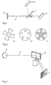
- the openwork mirror can be realized in different ways. Some embodiments are shown in FIG. 2.
- a round mirror can e.g. Pieces are cut out so that an impeller is formed (Fig. 2 a).
- a perforated mirror can also be produced by the arrangement of holes, for example by drilling (FIG. 2 b).
- a transparent substrate can be mirrored in places (Fig. 2 c).
- the openwork mirror can also be made directly as a metal mirror, e.g. B. made of copper or aluminum. The number of holes or mirror surfaces can be adapted to the corresponding application.
- this is arranged in the beam path so that the light hits the grating (7) at different angles.
Landscapes
- Physics & Mathematics (AREA)
- Electromagnetism (AREA)
- Engineering & Computer Science (AREA)
- Plasma & Fusion (AREA)
- Optics & Photonics (AREA)
- Lasers (AREA)
Description
- Die Erfindung betrifft eine Anordnung zur vergleichsweise schnellen Änderung der Wellenlänge eines Lasers mit einem im Strahlengang des Lichts im Laserresonator angeordneten rotierenden Spiegel, durch den ein Gitter ansteuerbar ist, wobei über die Änderung des Einfallwinkels des Lichts auf das Gitter die gewünschte Wellenlänge einstellbar ist. Außerdem bezieht sich die Erfindung auf ein Verfahren zum vergleichsweise schnellen Ändern der Wellenlänge eines gepulsten Lasers mit einem im Strahlengang des Lichts im Laserresonator angeordneten beweglichen Kippspiegel, durch den ein Gitter angesteuert wird, wobei über die Änderung des Einfallwinkels des Lichts auf das Gitter die gewünschte Wellenlänge eingestellt wird.
- Laser mit einer schnellen Abstimmung zwischen zwei Wellenlängen werden in einer vielzahl von Anwendungen eingesetzt, z.B. auch bei der Fernmessung von Schadstoffen mit Pulslasern mit Hilfe der differentiellen Absorptionstechnik. Der zeitliche Abstand der Laserpulse mit den zwei verschiedenen Wellenlängen sollte dabei zwischen einer und 10 Millisekunden liegen.
- Bekannt ist für die schnelle Abstimmung die Verwendung eines Gitters, das mit konstanter Winkelgeschwindigkeit im Resonator eines gepulsten Lasers rotiert. Im Verlauf einer Rotationsperiode durchfährt das Gitter alle möglichen Winkelstellungen, die die Emissionsfrequenz des Lasers bestimmen. Die gewünschte Laserfrequenz kann nun dadurch eingestellt werden, daß der Laser genau zu dem Zeitpunkt gezündet wird, in dem die Winkelstellung des rotierenden Gitters richtig ist. Somit besteht völlige Freiheit in der Auswahl der Laserfrequenzen bei jedem Laserpuls. Bei schnellgepulsten Lasern kann die Frequenz von aufeinander folgenden Pulsen beliebig bestimmt werden.
- Statt eines rotierenden Gitters wird häufig auch ein Drehspiegel oder ein rotierender Polygonspiegel verwendet, um das Gitter anzusteuern. Dies zeigt z.B. die DE-A-3 335 317, die eine Anordnung mit den Merkmalen des Oberbegriffs von Patentanspruch 1 beschreibt.
- Ein mit konstanter Amplitude schwingender Ablenkspiegel kann die gleiche Funktion erfüllen.
- Bei Pulsfolgefrequenzen von ca. 100 bis 1000 Pulsen pro Sekunde ergeben sich recht hohe Rotationsgeschwindigkeiten des Gitters oder Umlenkspiegels. Daraus folgt, daß der Zeitpunkt der Laserzündung mit sehr geringen Toleranzen, typischerweise ca. 0,1 Mikrosekunden, eingehalten werden muß. Diese Genauigkeit bedingt aufwendige Kontrolleinrichtungen und verursacht insbesondere bei gepulsten CO2-Lasern erhebliche technologische Probleme, die die Abstimmgenauigkeit vermindern und auch die Richtung des emittierten Strahls leicht verändern können.
- Die US-A-3,872,407 beschreibt ein Verfahren mit den Merkmalen des Oberbegriffs von Patentanspruch 5. Dort wird mit einer festen Amplitude der Auslenkung des Kippspiegels gearbeitet.
- Die FR-A-22 45 108 beschreibt eine Anordnung ähnlich derjenigen der DE-A-3 335 317, wobei eine angetriebene Lochscheibe in den Strahlengängen hinter einem halbdurchlässigen Spiegel angeordnet ist. Die Lochscheibe dient dort dazu, die Strahlen ein- bzw. auszuschalten, ohne diese zu reflektieren oder zu versetzen.
- Die EP-A-118 057 beschreibt eine mit ausgedehnten Strahlenbündeln arbeitende Vorrichtung, die zur Umschaltung zwischen zwei optischen Gesichtsfeldern dient. Hierzu ist eingangsseitig ein auf Drehung angetriebener Spiegel mit abwechselnd transparenten bzw. reflektierenden Segmenten vorgesehen, mit dessen Hilfe alternierend zwei ihm zugeleitete Lichtbündel zu einem gemeinsamen Detektor gelenkt werden.
- Ausgehend von einer Anordnung bzw. einem Verfahren mit den eingangs genannten Merkmalen liegt der Erfindung die Aufgabe zugrunde, eine einfach realisierbare Anordnung bzw. ein einfach realisierbares Verfahren zu schaffen, mit denen ohne Beeinflussing der Abstimmgenauigkeit oder der Strahlenjustierung zwischen verschiedenen Wellenlängen schnell umgeschaltet werden kann.
- Diese Aufgabe wird bei der erfindungsgemäßen Anordnung dadurch gelöst, daß der rotierende Spiegel mit Durchbrechungen versehen ist und das Licht alternierend auf das Gitter und ein zweites Gitter oder mindestens einen zweiten Spiegel fällt.
- Der Spiegel kann in Form eines Flügelrads, einer gelochten Scheibe oder eines durchsichtigen, stellenweise verspiegelten Substrats ausgebildet sein.
- In diesem Falle wird es bevorzugt, wenn die Flächen des Flügelrad-Spiegels geneigt sind.
- Bei einem gepulsten Laser wird es bevorzugt, wenn der Abstand zwischen zwei Durchbrüchen des Spiegels entsprechend der Pulsfolgefrequenz und unter Berücksichtigung der Rotationsgeschwindigkeit des Spiegels gewählt ist.
- Ist beispielsweise ein rotierender Lochspiegel vorgesehen, so läßt dieser den Laserstrahl im Resonator alternierend durch bzw. lenktdiesen ab.
- Die beiden so entstehenden Resonatorarme enthalten Abstimmelemente wie z.B. Gitter, die einzeln auf verschiedene Wellenlängen gestellt werden können. Da der Lochspiegel den Laserstrahl nur unterbricht oder reflektiert, treten auch keine kritischen Toleranzen zur Zündung des Lasers auf.
- Der Lochspiegel selber kann aus mehreren Segmenten bestehen, um so die erforderliche Drehgeschwindigkeit herabzusetzen. Bei einer gewünschten Abstimmfrequenz von z.B. 1000 Hertz und einem Spiegelrad mit fünf Segmenten und entsprechend vielen Durchbrüchen beträgt die erforderliche Drehfrequenz des Spiegels 6000 U/min. Diese Drehgeschwindigkeit kann ohne Schwierigkeiten erreicht werden. Mit entsprechender Auswuchtung kann ein vibrationsfreier Lauf erreicht werden, so daß diese Abstimmvorrichtung die übrigen Komponenten des Laserresonators nicht beeinflußt.
- Das erfindungsgemäße Verfahren istzur Lösung der erwähnten Aufgabe dadurch gekennzeichnet, daß der Kippspiegel mit konstanter Frequenz und variabler Amplitude angesteuert wird und daß der Laser jeweils in den Umkehrpunkten gezündet wird. Der Kippspiegel wird also so angesteuert, daß die gewünschten Wellenlängen dann eingestellt sind, wenn sich der Spiegel in den Umkehrpunkten befindet. Das erfordert eine Ansteuerung des Schwingspiegels mit konstanter Frequenz und variabler Amplitude. Die Steuerung der Amplitudenhöhe kann ohne besondere Schwierigkeiten durchgeführt werden. Da sich der Kippspiegel (Schwingspiegel) in den Umlenkpunkten nur langsam bewegt, ergibt sich in dieser Anordnung eine deutliche Reduzierung der erforderlichen Genauigkeit des Zündzeitpunkts auf Werte zwischen 10 und 100 Mikrosekunden. Eine solche Genauigkeit läßt sich auch mit gepulsten COZ-Lasern ohne besonderen Aufwand erreichen.
- Die Erfindung wird anhand der schematischen Zeichnung näher erläutert. Es zeigen:
- Fig. 1 eine Anordnung mit einem Chopperspiegel und zwei Gittern;
- Fig. 2 verschiedene Ausführungsformen für den durchbrochenen Spiegel und
- Fig. 3 die Funktionsweise des Kippspiegels.
- In der Ausführungsform gemäß Fig. 1 wird ein durchbrochener, in Pfeilrichtung rotierender Spiegel 1, in diesem Fall in Form eines Flügelrades, in den Laserresonator eingebaut. Der Winkel unter dem der Spiegel 1 befestigt wird, ist frei wählbar. Zwei Gitter 2 und 3 werden relativ zu dem Spiegel 1 angebracht.
- Befindet sich nun keine reflektierende Fläche im Strahlenweg 4, so wird der Laserresonator durch den Spiegel 1, das Gitter 2 und den Laserendspiegel 5 gebildet. Befindet sich ein Spiegelsegment im Strahlenweg 4, so wird der Resonator durch den Spiegel 1 und das Gitter 3 gebildet. Sowohl Gitter 2 als auch Gitter 3 können durch einen Steuerspiegel ersetzt werden, der das Licht zu dem dann vorhandenen Gitter 2 oder 3 ablenkt.
- Der durchbrochene Spiegel kann auf verschiedene Weise realisiert werden. Einige Ausführungsformen sind in Fig. 2 dargestellt. Aus einem runden Spiegel können z.B. Stücke so herausgeschnitten werden, daß ein Flügelrad entsteht (Fig. 2 a). Durch die Anordnung von Löchern, beispielsweise durch Bchren, ist ein durchbrochener Spiegel ebenfalls herstellbar (Fig. 2 b). Ein durchsichtiges Substrat kann stellenweise verspiegelt werden (Fig. 2 c). Man kann auch auf einer Lochscheibe Spiegelsegmente befestigen. Spiegelsegmente können dabei unter verschiedenen Winkeln auf die Lochscheibe aufgebracht werden, so daß das Licht auf das entsprechende Gitter unter verschiedenen Winkeln auftritt. Der durchbrochene Spiegel kann auch direkt als Metallspiegel hergestellt werden, z. B. aus Kupfer oder Aluminium. Der Anzahl der Löcher bzw. Spiegelflächen kann dem entsprechenden Anwendungsfall angepaßt werden.
- Bei Verwendung eines Kippspiegels 6, wie in Fig. 3 gezeigt, wird dieser im Strahlengang so angeordnet, daß das Licht unter verschiedenen Winkeln auf das Gitter (7) trifft.
Claims (5)
Priority Applications (1)
| Application Number | Priority Date | Filing Date | Title |
|---|---|---|---|
| AT86902358T ATE56109T1 (de) | 1985-03-12 | 1986-03-01 | Anordnung und verfahren zur schnellen umschaltung zwischen verschiedenen wellenlaengen eines lasers. |
Applications Claiming Priority (2)
| Application Number | Priority Date | Filing Date | Title |
|---|---|---|---|
| DE19853508707 DE3508707A1 (de) | 1985-03-12 | 1985-03-12 | Anordnung zur schnellen umschaltung zwischen verschiedenen wellenlaengen bei lasern |
| DE3508707 | 1985-03-12 |
Publications (2)
| Publication Number | Publication Date |
|---|---|
| EP0214288A1 EP0214288A1 (de) | 1987-03-18 |
| EP0214288B1 true EP0214288B1 (de) | 1990-08-29 |
Family
ID=6264900
Family Applications (1)
| Application Number | Title | Priority Date | Filing Date |
|---|---|---|---|
| EP86902358A Expired - Lifetime EP0214288B1 (de) | 1985-03-12 | 1986-03-01 | Anordnung und verfahren zur schnellen umschaltung zwischen verschiedenen wellenlängen eines lasers |
Country Status (5)
| Country | Link |
|---|---|
| US (1) | US4823351A (de) |
| EP (1) | EP0214288B1 (de) |
| JP (1) | JPS62502368A (de) |
| DE (2) | DE3508707A1 (de) |
| WO (1) | WO1986005631A1 (de) |
Families Citing this family (16)
| Publication number | Priority date | Publication date | Assignee | Title |
|---|---|---|---|---|
| DE3704338C2 (de) * | 1987-02-12 | 1995-04-06 | Gsf Forschungszentrum Umwelt | Einrichtung zur Erzeugung verschiedener Laserwellenlängen aus demselben Lasermedium |
| DE3741026A1 (de) * | 1987-12-03 | 1989-06-15 | Muetek Laser Und Opto Elektron | Verfahren und system zur (spuren-) gasanalyse |
| SE468337B (sv) * | 1991-05-08 | 1992-12-14 | Radians Innova Ab | Saett att anordna och justera in en laser samt laseranordning vilken genomfoer saettet |
| US5249192A (en) * | 1991-06-27 | 1993-09-28 | Laserscope | Multiple frequency medical laser |
| EP0552394B1 (de) * | 1992-01-24 | 1994-10-26 | Hewlett-Packard GmbH | Verfahren und Apparat zum Abstimmen der Wellenlänge in einer optischen Vorrichtung und deren Anwendung in einem Laser |
| US5329543A (en) * | 1992-08-24 | 1994-07-12 | Paschal Richard C | Pulsed laser using a moving intracavity photon deflector as a beam extractor |
| US5375132A (en) * | 1993-05-05 | 1994-12-20 | Coherent, Inc. | Solid state laser with interleaved output |
| SE501495C2 (sv) * | 1993-07-02 | 1995-02-27 | Ericsson Telefon Ab L M | Avstämbar optisk anordning |
| US6201820B1 (en) * | 1997-03-05 | 2001-03-13 | Silkroad, Inc. | Optically modulated laser beam transceiver |
| JP2000124528A (ja) * | 1998-10-12 | 2000-04-28 | Mitsubishi Electric Corp | レーザ装置、多段増幅レーザ装置およびこれらを用いたレーザ加工装置 |
| DE10065529A1 (de) * | 2000-12-28 | 2002-07-04 | Bosch Gmbh Robert | Laserstrahlquelle |
| US7336691B2 (en) * | 2005-03-24 | 2008-02-26 | Coherent, Inc. | Apparatus for combining beams from repetitively pulsed lasers along a common path |
| US7548573B2 (en) * | 2005-07-12 | 2009-06-16 | Santanu Basu | Rotary disk, rotary disk module, and rotary disk laser and amplifier configurations |
| US20070016177A1 (en) * | 2005-07-14 | 2007-01-18 | Boris Vaynberg | Laser ablation apparatus useful for hard tissue removal |
| EP2287980A1 (de) | 2009-08-21 | 2011-02-23 | Karlsruher Institut für Technologie | Durchstimmbare Laserlichtquelle auf Basis variabler optischer Pulsanregung und Verfahren zum Betreiben derselben |
| CN104950432B (zh) * | 2014-03-31 | 2017-12-15 | 大族激光科技产业集团股份有限公司 | 机械式激光功率衰减方法及其结构 |
Family Cites Families (16)
| Publication number | Priority date | Publication date | Assignee | Title |
|---|---|---|---|---|
| DE118057C (de) * | ||||
| US3725817A (en) * | 1964-09-02 | 1973-04-03 | Rca Corp | High power laser system |
| US3626322A (en) * | 1969-07-09 | 1971-12-07 | American Optical Corp | Method and apparatus for eliminating dominance or laser oscillations at one wavelength over those at another |
| US3753148A (en) * | 1972-04-06 | 1973-08-14 | Nasa | Infrared tunable laser |
| US3872407A (en) * | 1972-09-01 | 1975-03-18 | Us Navy | Rapidly tunable laser |
| FR2245108A1 (en) * | 1973-09-24 | 1975-04-18 | Commissariat Energie Atomique | Emission of coherent light of two wavelengths - from a resonant cavity laser |
| US4103254A (en) * | 1976-11-10 | 1978-07-25 | Chikami Leslie F | Tunable frequency laser |
| US4208637A (en) * | 1977-03-09 | 1980-06-17 | Agency Of Industrial Science & Technology, Ministry Of International Trade & Industry | Tunable optical device |
| GB2007014B (en) * | 1977-10-04 | 1982-03-31 | Commissariat Energie Atomique | Fast-switching multiwavelength laser |
| US4219786A (en) * | 1978-12-11 | 1980-08-26 | The United States Of America As Represented By The Secretary Of The Army | Polarization suppression of parasitic modes |
| DE2900728A1 (de) * | 1979-01-10 | 1980-07-24 | Max Planck Gesellschaft | Verfahren und einrichtung zum erzeugen von ultrakurzen laserimpulsen |
| US4425648A (en) * | 1980-12-29 | 1984-01-10 | Rockwell International Corporation | Wavelength selectivity of lasers and control thereof for rapid action measuring tasks |
| FR2505563B1 (fr) * | 1981-05-08 | 1986-02-14 | Comp Generale Electricite | Dispositif laser a frequences d'emission multiples |
| JPS5821387A (ja) * | 1981-07-29 | 1983-02-08 | Olympus Optical Co Ltd | レ−ザ照射装置 |
| US4601036A (en) * | 1982-09-30 | 1986-07-15 | Honeywell Inc. | Rapidly tunable laser |
| DE3307484C2 (de) * | 1983-03-03 | 1984-12-20 | Ego Entwicklungsgesellschaft für Optronik mbH, 2393 Glücksburg | Optisch-mechanischer Abtaster |
-
1985
- 1985-03-12 DE DE19853508707 patent/DE3508707A1/de not_active Ceased
-
1986
- 1986-03-01 US US07/006,561 patent/US4823351A/en not_active Expired - Fee Related
- 1986-03-01 WO PCT/EP1986/000104 patent/WO1986005631A1/de not_active Ceased
- 1986-03-01 JP JP61502115A patent/JPS62502368A/ja active Pending
- 1986-03-01 EP EP86902358A patent/EP0214288B1/de not_active Expired - Lifetime
- 1986-03-01 DE DE8686902358T patent/DE3673729D1/de not_active Expired - Lifetime
Also Published As
| Publication number | Publication date |
|---|---|
| US4823351A (en) | 1989-04-18 |
| DE3673729D1 (de) | 1990-10-04 |
| JPS62502368A (ja) | 1987-09-10 |
| WO1986005631A1 (fr) | 1986-09-25 |
| DE3508707A1 (de) | 1986-09-18 |
| EP0214288A1 (de) | 1987-03-18 |
Similar Documents
| Publication | Publication Date | Title |
|---|---|---|
| WO1986005631A1 (fr) | Agencement de commutation rapide entre differentes longueurs d'onde dans des lasers | |
| DE2719275C2 (de) | ||
| DE2416436C2 (de) | Laseranordnung | |
| EP0028615B1 (de) | Vorrichtung zur behandlung eines substrates mittels laserstrahlen | |
| DE69904753T2 (de) | Vorrrichung zur fertigung eines laserablatierten merkmals | |
| DE2828754A1 (de) | Rotierende, optische zerhackervorrichtung und verwendung derselben | |
| DE19748802B4 (de) | Optische Positionsmeßeinrichtung | |
| EP0835715A1 (de) | Vorrichtung und Verfahren zur Laser-Behandlung eines Werkstückes mittels eines Diodenlasers | |
| DE202008017745U1 (de) | Vorrichtung zum Führen eines Lichtstrahls | |
| WO2012035031A1 (de) | Trepanieroptik | |
| DE10239940A1 (de) | Lichtschranke oder Lichtgitter | |
| DE10228899A1 (de) | Einrichtung und Verfahren zur Laserstrahlablenkung für optische Messsysteme und optisches Element | |
| DE4038928A1 (de) | Vorrichtung zum perforieren von zigaretten | |
| DE3722586C2 (de) | Optische Leitvorrichtung | |
| EP1119437A1 (de) | Vorrichtung zur behandlung eines substrates mittels laserstrahlung | |
| DE2922976C2 (de) | Vorrichtung zur Erzeugung einer Matrix von Perforationen in einer sich mit konstanter Geschwindigkeit bewegenden Materialbahn mittels einer Anzahl gepulster Laserstrahlen | |
| EP0591559B1 (de) | Verfahren und Vorrichtung zum Gravieren von Rundschablonen | |
| DE4224599A1 (de) | Elektrostatische Ablenkeinheit | |
| EP0634636B1 (de) | Interferometer nach Michelson | |
| DE69827549T2 (de) | Vorrichtung zur Verarbeitung einer Materialbahn quer zu ihrer Längsrichtung | |
| DE2042229C3 (de) | Mehrstufige, steuerbare Lichtstrahlablenkvorrichtung | |
| EP1358036B1 (de) | Vorrichtung zur substratbehandlung mittels laserstrahlung | |
| DE4034744C2 (de) | Vorrichtung zur variablen Laserstrahlteilung und Führung der Teilstrahlen | |
| EP0536683A1 (de) | Vorrichtung zur Führung eines Laserstrahls | |
| WO2003009047A2 (de) | Vorrichtung zur ablenkung des laserstrahls |
Legal Events
| Date | Code | Title | Description |
|---|---|---|---|
| PUAI | Public reference made under article 153(3) epc to a published international application that has entered the european phase |
Free format text: ORIGINAL CODE: 0009012 |
|
| 17P | Request for examination filed |
Effective date: 19860905 |
|
| AK | Designated contracting states |
Kind code of ref document: A1 Designated state(s): AT BE CH DE FR GB IT LI LU NL SE |
|
| RIN1 | Information on inventor provided before grant (corrected) |
Inventor name: HOEFFGEN, HANSJUERGEN Inventor name: ENDEMANN, MARTIN |
|
| 17Q | First examination report despatched |
Effective date: 19880615 |
|
| GRAA | (expected) grant |
Free format text: ORIGINAL CODE: 0009210 |
|
| AK | Designated contracting states |
Kind code of ref document: B1 Designated state(s): AT BE CH DE FR GB IT LI LU NL SE |
|
| REF | Corresponds to: |
Ref document number: 56109 Country of ref document: AT Date of ref document: 19900915 Kind code of ref document: T |
|
| ET | Fr: translation filed | ||
| REF | Corresponds to: |
Ref document number: 3673729 Country of ref document: DE Date of ref document: 19901004 |
|
| GBT | Gb: translation of ep patent filed (gb section 77(6)(a)/1977) | ||
| ITF | It: translation for a ep patent filed | ||
| ITTA | It: last paid annual fee | ||
| PLBE | No opposition filed within time limit |
Free format text: ORIGINAL CODE: 0009261 |
|
| STAA | Information on the status of an ep patent application or granted ep patent |
Free format text: STATUS: NO OPPOSITION FILED WITHIN TIME LIMIT |
|
| 26N | No opposition filed | ||
| PGFP | Annual fee paid to national office [announced via postgrant information from national office to epo] |
Ref country code: SE Payment date: 19920302 Year of fee payment: 7 |
|
| PGFP | Annual fee paid to national office [announced via postgrant information from national office to epo] |
Ref country code: LU Payment date: 19920312 Year of fee payment: 7 |
|
| PGFP | Annual fee paid to national office [announced via postgrant information from national office to epo] |
Ref country code: AT Payment date: 19920313 Year of fee payment: 7 |
|
| PGFP | Annual fee paid to national office [announced via postgrant information from national office to epo] |
Ref country code: NL Payment date: 19920331 Year of fee payment: 7 |
|
| EPTA | Lu: last paid annual fee | ||
| PGFP | Annual fee paid to national office [announced via postgrant information from national office to epo] |
Ref country code: GB Payment date: 19930226 Year of fee payment: 8 |
|
| PG25 | Lapsed in a contracting state [announced via postgrant information from national office to epo] |
Ref country code: LU Free format text: LAPSE BECAUSE OF NON-PAYMENT OF DUE FEES Effective date: 19930301 Ref country code: AT Effective date: 19930301 |
|
| PG25 | Lapsed in a contracting state [announced via postgrant information from national office to epo] |
Ref country code: SE Effective date: 19930302 |
|
| PGFP | Annual fee paid to national office [announced via postgrant information from national office to epo] |
Ref country code: BE Payment date: 19930311 Year of fee payment: 8 |
|
| PGFP | Annual fee paid to national office [announced via postgrant information from national office to epo] |
Ref country code: CH Payment date: 19930317 Year of fee payment: 8 |
|
| PGFP | Annual fee paid to national office [announced via postgrant information from national office to epo] |
Ref country code: FR Payment date: 19930329 Year of fee payment: 8 |
|
| PGFP | Annual fee paid to national office [announced via postgrant information from national office to epo] |
Ref country code: DE Payment date: 19930525 Year of fee payment: 8 |
|
| PG25 | Lapsed in a contracting state [announced via postgrant information from national office to epo] |
Ref country code: NL Effective date: 19931001 |
|
| NLV4 | Nl: lapsed or anulled due to non-payment of the annual fee | ||
| PG25 | Lapsed in a contracting state [announced via postgrant information from national office to epo] |
Ref country code: GB Effective date: 19940301 |
|
| PG25 | Lapsed in a contracting state [announced via postgrant information from national office to epo] |
Ref country code: LI Effective date: 19940331 Ref country code: CH Effective date: 19940331 Ref country code: BE Effective date: 19940331 |
|
| BERE | Be: lapsed |
Owner name: BATTELLE-INSTITUT E.V. Effective date: 19940331 |
|
| GBPC | Gb: european patent ceased through non-payment of renewal fee |
Effective date: 19940301 |
|
| PG25 | Lapsed in a contracting state [announced via postgrant information from national office to epo] |
Ref country code: FR Effective date: 19941130 |
|
| REG | Reference to a national code |
Ref country code: CH Ref legal event code: PL |
|
| PG25 | Lapsed in a contracting state [announced via postgrant information from national office to epo] |
Ref country code: DE Effective date: 19941201 |
|
| REG | Reference to a national code |
Ref country code: FR Ref legal event code: ST |
|
| EUG | Se: european patent has lapsed |
Ref document number: 86902358.0 Effective date: 19931008 |
|
| PG25 | Lapsed in a contracting state [announced via postgrant information from national office to epo] |
Ref country code: IT Free format text: LAPSE BECAUSE OF NON-PAYMENT OF DUE FEES Effective date: 20050301 |