EP0211265B1 - Method and apparatus for the wet treatment of textile materials in rope form - Google Patents
Method and apparatus for the wet treatment of textile materials in rope form Download PDFInfo
- Publication number
- EP0211265B1 EP0211265B1 EP86109426A EP86109426A EP0211265B1 EP 0211265 B1 EP0211265 B1 EP 0211265B1 EP 86109426 A EP86109426 A EP 86109426A EP 86109426 A EP86109426 A EP 86109426A EP 0211265 B1 EP0211265 B1 EP 0211265B1
- Authority
- EP
- European Patent Office
- Prior art keywords
- tube section
- intensive treatment
- textile material
- treatment
- intensive
- Prior art date
- Legal status (The legal status is an assumption and is not a legal conclusion. Google has not performed a legal analysis and makes no representation as to the accuracy of the status listed.)
- Expired
Links
- 239000004753 textile Substances 0.000 title claims description 51
- 239000000463 material Substances 0.000 title claims description 26
- 238000000034 method Methods 0.000 title claims description 8
- 238000011144 upstream manufacturing Methods 0.000 claims description 4
- 238000012545 processing Methods 0.000 claims description 2
- 239000011295 pitch Substances 0.000 claims 1
- 238000004804 winding Methods 0.000 claims 1
- 238000013461 design Methods 0.000 description 4
- 239000000126 substance Substances 0.000 description 4
- 230000000694 effects Effects 0.000 description 3
- 238000003860 storage Methods 0.000 description 3
- 238000011982 device technology Methods 0.000 description 2
- 230000001105 regulatory effect Effects 0.000 description 2
- 238000012549 training Methods 0.000 description 2
- 230000001133 acceleration Effects 0.000 description 1
- 230000002411 adverse Effects 0.000 description 1
- 208000028659 discharge Diseases 0.000 description 1
- 238000009826 distribution Methods 0.000 description 1
- 238000002360 preparation method Methods 0.000 description 1
- 238000003892 spreading Methods 0.000 description 1
- 238000004381 surface treatment Methods 0.000 description 1
- XLYOFNOQVPJJNP-UHFFFAOYSA-N water Substances O XLYOFNOQVPJJNP-UHFFFAOYSA-N 0.000 description 1
Images
Classifications
-
- D—TEXTILES; PAPER
- D06—TREATMENT OF TEXTILES OR THE LIKE; LAUNDERING; FLEXIBLE MATERIALS NOT OTHERWISE PROVIDED FOR
- D06B—TREATING TEXTILE MATERIALS USING LIQUIDS, GASES OR VAPOURS
- D06B3/00—Passing of textile materials through liquids, gases or vapours to effect treatment, e.g. washing, dyeing, bleaching, sizing, impregnating
- D06B3/28—Passing of textile materials through liquids, gases or vapours to effect treatment, e.g. washing, dyeing, bleaching, sizing, impregnating of fabrics propelled by, or with the aid of, jets of the treating material
Definitions
- the invention relates to a method and a device, in each case for the wet treatment of textile goods in strand form according to the preamble of patent claim 1 and of patent claim 3.
- the textile goods are conveyed onwards by means of the transport reel to the intensive treatment line in the latter by means of the wet treatment fleet.
- the wet treatment fleet In order to ensure a secure transport of goods through the intensive treatment line, the wet treatment fleet must be introduced into the intensive treatment line at a speed which is substantially greater than the speed of circulation of the textile goods. This relative speed between the wet treatment liquor and the textile material means that the surface of the textile material is more or less damaged (pilling effect).
- the invention is therefore based on the object, in order to avoid this disadvantage, to improve the method initially described with regard to its type and the associated device in such a way that surface damage caused by a relative speed between the textile material and the treatment liquor is avoided.
- the textile goods are guided horizontally into a correspondingly arranged intensive treatment line, since influencing the speed of the wet treatment liquor simply by reducing the feed speed in the nozzle or overflow unit alone cannot fundamentally bring about a final effective improvement.
- the intensive treatment line is generally a somehow downward line, at the upper end of which the textile goods and the wet treatment liquor are fed, which on the other hand are discharged at the lower end of the wet treatment line.
- the intensive treatment line and thus the conveying path of the textile goods are aligned horizontally and at the same time the feed rate of the treatment liquor at the inlet end of the intensive treatment line is matched to the transport speed of the textile goods, there is a considerable risk of the intensive treatment line becoming blocked relatively soon due to a lack of sufficient conveying action on the textile goods and consequently the invention as a further unconditional measure, the pulling action on the textile material from the outlet side of the intensive treatment line, for which purpose the second reel device to be provided is used in terms of device technology. Of course, this should operate at essentially the same speed as the first reel device, so to speak, upstream of the intensive treatment line. This is the only way to ensure the safe transport of the textile goods through the intensive treatment line, but also to avoid the influence of special, namely excessively high tensile forces on the textile goods.
- the intensive treatment line in the width direction to expand conically towards the outlet end.
- the textile goods to be spread from the original strand shape at the inlet end of the intensive treatment line to a practically fully spread web.
- the inventive design in particular including the training measures according to the subclaims, creates a procedure and an associated device which actually permit wet treatment of the textile goods without surface damage, at least as far as surface damage due to a relative speed between the textile goods and wet treatment fleet is concerned, all with a simultaneous guarantee a secure transport of the textile goods through the intensive treatment line.
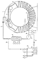
- a wet treatment container 1 in which textile material 2 to be treated is in circulation.
- the textile material 2 which is stacked in the interior of the wet treatment container 1, is picked up from the lower region of the wet treatment container 1 via a first reel device 3 and fed to an intensive treatment section 4.
- the textile material 2 moves through this intensive treatment section 4 to a second reel device 5 which pulls the textile material through the intensive treatment section 4 and releases it again into the lower region of the wet treatment container 1.
- a so-called overflow unit 6 is provided, via which the treatment liquor can be introduced into the interior of the wet treatment section 4 under a certain pressure, at the same time at a certain speed.
- the textile material 2 is brought into intensive contact with the wet treatment liquor within the intensive treatment section 4 or flushed through by it, on which the actual wet treatment effect is based.
- the intensive treatment section 4 is a section of a pipe section with a horizontal arrangement.
- the wet treatment liquor does not experience any particular acceleration when it passes through the intensive treatment section 4, i.e. their speed remains constant.
- the speed of the supply of the wet treatment liquor via the overflow unit 6 to the intensive treatment section 4 is now adjusted to the transport speed of the two reel devices 3 and 5, namely by regulating all speeds at essentially the same size. In this way, there is no relative speed between the textile material 2 and the wet treatment liquor within the intensive treatment section 4.
- the two reel devices 3 and 5 are driven devices, although the second reel device 5 can also operate at a slightly higher speed than the first reel device 3, in order to prevent the intensive treatment line 4 from being blocked in any way by the textile material 2.
- the overflow unit 6 is first connected via an inlet line 7 to a heat exchanger 8, which in turn is connected to a circulation pump 9. This is connected to the lower inner region 11 of the wet treatment container 1 via a suction line 10.
- a branch 1 5 leads from the inlet line 7 into the interior of the storage container 12.
- valves In the entire circulation line system as well as in the lines of the metering system, a series of valves is provided which, in the usual manner, supply and discharge treatment liquor to the wet treatment tank 1, hot water or steam to the heat exchanger 8 and chemicals or already dissolved chemicals to the storage tank 12 and also serve there for the supply of wet treatment liquor for the preparation of the chemicals.
- a nozzle unit can be provided, in which case the wet treatment liquor is then introduced into the intensive treatment section 4 under the action of a particular pump pressure.
- the feed rate of the wet treatment liquor to the intensive treatment section 4 can be controlled by corresponding regulation of the output of the circulation pump 9, this is possible with the overflow unit 6 in that the access cross section from the overflow tank to the entry of the treatment liquor into the intensive treatment section 4 is regulated in any suitable way;
- the corresponding is no longer shown, but can be easily implemented by the person skilled in the art, since supply control of overflow units from or to these have already been implemented in various ways.
Landscapes
- Engineering & Computer Science (AREA)
- Textile Engineering (AREA)
- Treatment Of Fiber Materials (AREA)
Description
Die Erfindung betrifft ein Verfahren und eine Vorrichtung, jeweils zur Naßbehandlung von Textilgut in Strangform gemäß Oberbegriff des Patentanspruchs 1 bzw. des Patentanspruchs 3.The invention relates to a method and a device, in each case for the wet treatment of textile goods in strand form according to the preamble of patent claim 1 and of patent claim 3.
Bei der bisherigen Naßbehandlungsweise von Textilgut in Strangform unter Verwendung von sogenannten Düsen- oder Overflowmaschinen wird das Textilgut nach seiner Zuführung mittels der Transporthaspel zu der Intensivbehandlungsstrecke in dieser mittels der Naßbehandlungsflotte weitertransportiert. Dabei muß zur Gewährleistung eines gesicherten Warentransports durch die Intensivbehandlungsstrecke die Naßbehandlungsflotte mit einer Geschwindigkeit in die Intensivbehandlungsstrecke eingeführt werden, die wesentlich größer ist als die Umlaufgeschwindigkeit des Textilguts. Diese Relativgeschwindigkeit zwischen Naßbehandlungsflotte und Textilgut führt dazu, daß die Oberfläche des Textilguts mehr oder weniger beschädigt wird (Pillingeffekt).In the previous wet treatment of textile goods in the form of strands using so-called nozzle or overflow machines, the textile goods are conveyed onwards by means of the transport reel to the intensive treatment line in the latter by means of the wet treatment fleet. In order to ensure a secure transport of goods through the intensive treatment line, the wet treatment fleet must be introduced into the intensive treatment line at a speed which is substantially greater than the speed of circulation of the textile goods. This relative speed between the wet treatment liquor and the textile material means that the surface of the textile material is more or less damaged (pilling effect).
Verständlicherweise sind derartige Oberflächenbeschädigungen des Textilguts, die sich auch noch auf die Weiterverarbeitung desselben nachteilig auswirken können, an sich immer zu vermeiden.Understandably, such surface damage to the textile goods, which can also have an adverse effect on the further processing of the textile goods, should always be avoided.
Der Erfindung liegt daher die Aufgabe zugrunde, zur Vermeidung dieses Nachteils, das eingangs hinsichtlich seiner Gattung bezeichnete Verfahren und die zugehörige Vorrichtung so zu verbessern, daß Oberflächenbeschädigungen bedingt durch eine Relativgeschwindigkeit zwischen Textilgut und Behandlungsflotte vermieden sind.The invention is therefore based on the object, in order to avoid this disadvantage, to improve the method initially described with regard to its type and the associated device in such a way that surface damage caused by a relative speed between the textile material and the treatment liquor is avoided.
Diese Aufgabe wird erfindungsgemäß in verfahrenstechnischer Hinsicht durch die im kennzeichnenden Teil des Patentanspruchs 1 und in vorrichtungstechnischer Hinsicht durch die im kennzeichnenden Teil des Patentanspruchs 3 angegebenen Maßnahmen gelöst.This object is achieved in procedural terms by the measures specified in the characterizing part of claim 1 and in terms of device technology by the measures specified in the characterizing part of claim 3.
Wesentlich für die erfindungsgemäße Ausbildung ist zunächst einmal die horizontale Führung des Textilguts in eine entsprechend angeordnete Intensivbehandlungsstrecke, da die Beeinflussung der Geschwindigkeit der Naßbehandlungsflotte lediglich durch Reduzierung der Zuführungsgeschwindigkeit in der Düsen- bzw. Overfloweinheit in Alleinstellung grundsätzlich keine endgültige wirkungsvolle Verbesserung bringen kann. Dies ist darauf zurückzuführen, daß bei der bisher bekannten Verfahrensweise und den zugehörigen Vorrichtungen die Intensivbehandlungsstrecke in der Regel eine irgendwie nach unten geführte Strecke ist, an deren oberen Ende das Textilgut und die Naßbehandlungsflotte zugeführt werden, die andererseits am unteren Ende der Naßbehandlungsstrecke abgeführt werden. Würde nun die Geschwindigkeit der Naßbehandlungsflotte am Einlaufende der Intensivbehandlungsstrecke so weit reduziert, daß keine Relativgeschwindigkeit zwischen Textilgut und Naßbehandlungsflotte bestünde, so würde dies nur für das Einlaufende der Naßintensivbehandlungsstrecke Geltung haben können; denn im weiteren Verlauf würde die Naßbehandlungsflotte aufgrund der Möglichkeit des praktisch freien Falls zunehmend schneller werden, so daß wiederum eine zunehmend größere Relativgeschwindigkeit in Hinblick auf das Textilgut bestünde.First of all, it is essential for the design according to the invention that the textile goods are guided horizontally into a correspondingly arranged intensive treatment line, since influencing the speed of the wet treatment liquor simply by reducing the feed speed in the nozzle or overflow unit alone cannot fundamentally bring about a final effective improvement. This is due to the fact that, in the previously known procedure and the associated devices, the intensive treatment line is generally a somehow downward line, at the upper end of which the textile goods and the wet treatment liquor are fed, which on the other hand are discharged at the lower end of the wet treatment line. If the speed of the wet treatment liquor at the inlet end of the intensive treatment line were reduced to such an extent that there was no relative speed between the textile goods and the wet treatment liquor, this would only be valid for the inlet end of the wet intensive treatment line; because in the further course, the wet treatment liquor would become increasingly faster due to the possibility of practically free fall, so that there would in turn be an increasingly greater relative speed with regard to the textile material.
Wird nun aber die Intensivbehandlungsstrecke und damit der Förderweg des Textilguts horizontal ausgerichtet und gleichzeitig die Zuführungsgeschwindigkeit der Behandlungsflotte am Einlaufende der Intensivbehandlungsstrecke auf die Transportgeschwindigkeit des Textilguts abgestimmt, so besteht eine erhebliche Gefahr der verhältnismäßig baldigen Verstopfung der Intensivbehandlungsstrecke mangels hinreichender Fördereinwirkung auf das Textilgut und demzufolge sieht die Erfindung als weitere bedingungslose Maßnahme die ziehende Einwirkung auf das Textilgut von der Auslaufsseite der Intensivbehandlungsstrecke aus vor, wozu in vorrichtungstechnischer Hinsicht die dort vorzusehende zweite Haspeleinrichtung dient. Diese sollte selbstverständlich im wesentlichen mit derselben Geschwindigkeit arbeiten wie die der Intensivbehandlungsstrecke vorgeschaltete sozusagen erste Haspeleinrichtung. Nur hierdurch wird einerseits ein gesicherter Transport des Textilguts durch die Intensivbehandlungsstrecke sichergestellt, andererseits aber auch die Vermeidung der Einwirkung besonderer, nämlich übermäßig hoher Zugkräfte auf das Textilgut.If, however, the intensive treatment line and thus the conveying path of the textile goods are aligned horizontally and at the same time the feed rate of the treatment liquor at the inlet end of the intensive treatment line is matched to the transport speed of the textile goods, there is a considerable risk of the intensive treatment line becoming blocked relatively soon due to a lack of sufficient conveying action on the textile goods and consequently the invention as a further unconditional measure, the pulling action on the textile material from the outlet side of the intensive treatment line, for which purpose the second reel device to be provided is used in terms of device technology. Of course, this should operate at essentially the same speed as the first reel device, so to speak, upstream of the intensive treatment line. This is the only way to ensure the safe transport of the textile goods through the intensive treatment line, but also to avoid the influence of special, namely excessively high tensile forces on the textile goods.
Einerseits in Hinblick auf eine möglichst gleichmäßige Verteilung der von der zweiten Haspeleinrichtung auf das Textilgut einwirkenden Zugkraft und andererseits aber auch in Hinblick auf eine möglichst gleichmäßige Einwirkung der Naßbehandlungsflotte auf das Textilgut während des gemeinsamen Hindurchlaufs durch die Intensivbehandlungsstrecke empfiehlt sich in Weiterbildung, die Intensivbehandlungsstrecke in Breitenrichtung konisch in Richtung auf das Auslaßende hin zu erweitern. Dadurch besteht die Möglichkeit zur Ausbreitung des Textilguts aus der ursprünglichen Strangform am Einlaßende der Intensivbehandlungsstrecke zu einer praktisch voll ausgebreiteten Bahn. Um dieses Ausbreiten zu erleichtern bzw. zu begünstigen, obwohl das Textilgut unter der Einwirkung einer Zugkraft aufgebracht von der zweiten Haspeleinrichtung steht, empfiehlt sich die Ausbildung der letzteren als sogenannte Breitstreckwalze, d.h. als eine solche Walze, die bei der Herüberführung des Textilguts über einen Teil ihres Umfangs dieses fortlaufend quer zur Transportrichtung, also in Breitenrichtung des Textilguts, ausbreitet.On the one hand, with regard to the distribution of the tensile force acting on the textile goods from the second reel device as evenly as possible, and on the other hand with regard to the most uniform possible influence of the wet treatment liquor on the textile goods during the joint passage through the intensive treatment line, further training is recommended, the intensive treatment line in the width direction to expand conically towards the outlet end. This enables the textile goods to be spread from the original strand shape at the inlet end of the intensive treatment line to a practically fully spread web. In order to facilitate or favor this spreading, although the textile material is applied by the second reel device under the action of a tensile force, it is advisable to design the latter as a so-called spreader roll, i.e. as such a roller which, when the textile goods are transferred over a part of their circumference, continuously spreads them across the transport direction, that is to say in the width direction of the textile goods.
Durch die erfindungsgemäße Ausbildung, insbesondere unter Einbeziehung der Weiterbildungsmaßnahmen gemäß den Unteransprüchen ist insgesamt eine Verfahrensweise und eine zugehörige Vorrichtung geschaffen, die tatsächlich eine oberflächenbeschädigungsfreie Naßbehandlung des Textilguts zulassen, jedenfalls was Oberflächenbeschädigungen bedingt durch eine Relativgeschwindigkeit zwischen Textilgut und Naßbehandlungsflotte betrifft, dies alles bei gleichzeitiger Gewährleistung eines gesicherten Transports des Textilguts durch die Intensivbehandlungsstrecke hindurch.The inventive design, in particular including the training measures according to the subclaims, creates a procedure and an associated device which actually permit wet treatment of the textile goods without surface damage, at least as far as surface damage due to a relative speed between the textile goods and wet treatment fleet is concerned, all with a simultaneous guarantee a secure transport of the textile goods through the intensive treatment line.
Nachfolgend wird die Erfindung weiter ins einzelne gehend anhand einer zweckmäßigen Ausführungsform unter gleichzeitiger Bezugnahme auf die Zeichnung beschrieben, die eine schematische Darstellung einer erfindungsgemäß ausgebildeten Naßbehandlungsvorrichtung zeigt, die nach dem Overflowprinzip arbeitet.In the following, the invention will be described in more detail with reference to an expedient embodiment with simultaneous reference to the drawing, which shows a schematic representation of a Nassbe designed according to the invention shows action device that works on the overflow principle.
In der Zeichnung ist ein Naßbehandlungsbehälter 1 zu ersehen, in dem zu behandelndes Textilgut 2 im Umlauf steht. Das im Inneren des Naßbehandlungsbehälter 1 abgetafelte Textilgut 2 wird über eine erste Haspeleinrichtung 3 vom unteren Bereich des Naßbehandlungsbehälters 1 aufgenommen und einer Intensivbehandlungsstrecke 4 zugeführt. Das Textilgut 2 bewegt sich durch diese Intensivbehandlungsstrecke 4 hindurch zu einer zweiten Haspeleinrichtung 5 hin, die das Textilgut unter Zugeinwirkung durch die Intensivbehandlungsstrecke 4 hindurchzieht und wieder in den unteren Bereich des Naßbehandlungsbehälters 1 abgibt.In the drawing, a wet treatment container 1 can be seen, in which textile material 2 to be treated is in circulation. The textile material 2, which is stacked in the interior of the wet treatment container 1, is picked up from the lower region of the wet treatment container 1 via a first reel device 3 and fed to an intensive treatment section 4. The textile material 2 moves through this intensive treatment section 4 to a
Am Eingangsbereich der Intensivbehandlungsstrecke 4 ist eine sogenannte Overflow-Einheit 6 vorgesehen, über die Behandlungsflotte in das Innere der Naßbehandlungsstrecke 4 unter gewissem Druck einführbar ist, und zwar gleichzeitig mit einer bestimmten Geschwindigkeit. Auf diese Weise wird das Textilgut 2 mit der Naßbehandlungsflotte innerhalb der Intensivbehandlungsstrecke 4 intensiv in Kontakt gebracht bzw. von dieser durchspült, worauf die eigentliche Naßbehandlungswirkung beruht.At the entrance area of the intensive treatment section 4, a so-called overflow unit 6 is provided, via which the treatment liquor can be introduced into the interior of the wet treatment section 4 under a certain pressure, at the same time at a certain speed. In this way, the textile material 2 is brought into intensive contact with the wet treatment liquor within the intensive treatment section 4 or flushed through by it, on which the actual wet treatment effect is based.
Die Intensivbehandlungsstrecke 4 ist eine als Rohrstrecke gestaltete Strecke mit horizontaler Anordnung. Demzufolge erfährt die Naßbehandlungsflotte beim Durchlauf durch die Intensivbehandlungsstrecke 4 keine besondere Beschleunigung, d.h. ihre Geschwindigkeit bleibt konstant. In erfindungsgemäßer Ausbildung ist nun die Geschwindigkeit der Zuführung der Naßbehandlungsflotte über die Overflow-Einheit 6 zur Intensivbehandlungsstrecke 4 auf die Transportgeschwindigkeit der beiden Haspeleinrichtungen 3 und 5 abgestellt, nämlich durch im wesentlichen gleich große Einregelung aller Geschwindigkeiten. Auf diese Weise besteht keine Relativgeschwindigkeit zwischen Textilgut 2 und Naßbehandlungsflotte innerhalb der Intensivbehandlungsstrecke 4.The intensive treatment section 4 is a section of a pipe section with a horizontal arrangement. As a result, the wet treatment liquor does not experience any particular acceleration when it passes through the intensive treatment section 4, i.e. their speed remains constant. In the embodiment according to the invention, the speed of the supply of the wet treatment liquor via the overflow unit 6 to the intensive treatment section 4 is now adjusted to the transport speed of the two
Die beiden Haspeleinrichtungen 3 und 5 sind angetriebene Einrichtungen, wobei allerdings die zweite Haspeleinrichtung 5 auch mit einer geringfügig höheren Geschwindigkeit arbeiten kann als die erste Haspeleinrichtung 3, um so auf jeden Fall eine irgendwie .verursachte Verstopfung der Intensivbehandlungsstrecke 4 durch das Textilgut 2 zu verhindern.The two
Die Overflow-Einheit 6 ist über eine Zulaufleitung 7 zunächst an einen Wärmetauscher 8 angeschlossen, der seinerseits an einer Umwälzpumpe 9 angeschlossen ist. Diese steht über eine Saugleitung 10 mit dem unteren inneren Bereich 11 des Naßbehandlungsbehälters 1 in Verbindung. Zur Zuführung von der Behandlungsflotte zu zusetzenden Chemikalien dient ein Speicherbehälter 12 mit nachgeschalteter Pumpe 13, deren Druckleitung 14 in die Saugleitung 10 der Umwälzpumpe 9 einmündet.The overflow unit 6 is first connected via an inlet line 7 to a heat exchanger 8, which in turn is connected to a
Von der Zulaufleitung 7 aus führt eine Abzweigung 1 5 in das Innere des Speicherbehälters 12.A branch 1 5 leads from the inlet line 7 into the interior of the
Im gesamten Umwälzleitungssystem sowie in den Leitungen des Dosiersystems ist eine Reihe von Ventilen vorgesehen, die in üblicher Weise der Zu- und Abführung von Behandlungsflotte zum Naßbehandlungsbehälter 1, von Heißwasser bzw. -dampf zum Wärmetauscher 8 und von Chemikalien bzw. bereits aufgelösten Chemikalien zum Speicherbehälter 12 und auch dort zur Zuführung von Naßbehandlungsflotte zum Ansetzen der Chemikalien dienen. Hierbei handelt es sich um übliche Einrichtungen, die nicht näher erläutert werden müssen.In the entire circulation line system as well as in the lines of the metering system, a series of valves is provided which, in the usual manner, supply and discharge treatment liquor to the wet treatment tank 1, hot water or steam to the heat exchanger 8 and chemicals or already dissolved chemicals to the
Durch die erwähnte gleichgroße Ausbildung der Umlaufgeschwindigkeit des Textilguts 2 und der Naßbehandlungsflotte in der Intensivbehandlungsstrecke 4 und die dadurch vermiedene Relativgeschwindigkeit zwischen Textilgut 2 und Naßbehandlungsflotte wird in der angestrebten Weise eine schonende Oberflächenbehandlung des Textilguts 2 erreicht.Due to the above-mentioned design of the circulation speed of the textile goods 2 and the wet treatment liquor in the intensive treatment section 4 and the relative speed thus avoided between textile goods 2 and the wet treatment liquor, a gentle surface treatment of the textile goods 2 is achieved in the desired manner.
Anstelle der Overflow-Einheit 6 kann eine Düsen-Einheit vorgesehen sein, wobei dann die Naßbehandlungsflotte unter der Einwirkung eines besonderen Pumpendrucks in die Intensivbehandlungsstrecke 4 eingeführt wird.Instead of the overflow unit 6, a nozzle unit can be provided, in which case the wet treatment liquor is then introduced into the intensive treatment section 4 under the action of a particular pump pressure.
Während bei einer Düsen-Einheit die Zuführgeschwindigkeit der Naßbehandlungsflotte zur Intensivbehandlungsstrecke 4 durch entsprechende Regelung der Leistung der Umwälzpumpe 9 gesteuert werden kann, ist dies bei der Overflow-Einheit 6 dadurch möglich, daß der Zutrittsquerschnitt von dem Überlaufbehälter zu dem Eintritt der Behandlungsflotte in die Intensivbehandlungsstrecke 4 in jeder hierzu geeigneten Weise geregelt wird; entsprechendes ist zwar nicht mehr dargestellt, jedoch für den Fachmann ohne weiteres realisierbar, da eine Zuführungsregelung von Overflow-Einheiten aus bzw. zu diesen hin bereits verschiedentlich realisiert worden sind.While in a nozzle unit the feed rate of the wet treatment liquor to the intensive treatment section 4 can be controlled by corresponding regulation of the output of the
Durch eine entsprechende Regelung der Overflow- Einheit wird also im Ergebnis dasselbe erreicht wie durch entsprechende Regelung der der Düsen-Einheit vorgeschalteten Umwälzpumpe 9, so daß im Ergebnis in beiden Fällen eine oberflächenschonende Behandlung des Textilguts 2 möglich ist.Appropriate control of the overflow unit thus achieves the same result as appropriate control of the
Claims (7)
Applications Claiming Priority (2)
| Application Number | Priority Date | Filing Date | Title |
|---|---|---|---|
| DE3528387 | 1985-08-07 | ||
| DE19853528387 DE3528387A1 (en) | 1985-08-07 | 1985-08-07 | METHOD AND DEVICE FOR WET TREATING TEXTILE GOODS IN STRAND SHAPE |
Publications (2)
| Publication Number | Publication Date |
|---|---|
| EP0211265A1 EP0211265A1 (en) | 1987-02-25 |
| EP0211265B1 true EP0211265B1 (en) | 1989-06-14 |
Family
ID=6277963
Family Applications (1)
| Application Number | Title | Priority Date | Filing Date |
|---|---|---|---|
| EP86109426A Expired EP0211265B1 (en) | 1985-08-07 | 1986-07-10 | Method and apparatus for the wet treatment of textile materials in rope form |
Country Status (6)
| Country | Link |
|---|---|
| US (1) | US4726088A (en) |
| EP (1) | EP0211265B1 (en) |
| CN (1) | CN86105725A (en) |
| DE (2) | DE3528387A1 (en) |
| DK (1) | DK332686A (en) |
| SU (1) | SU1463139A3 (en) |
Families Citing this family (7)
| Publication number | Priority date | Publication date | Assignee | Title |
|---|---|---|---|---|
| DE3724075A1 (en) * | 1987-07-21 | 1989-02-02 | Hoechst Ag | METHOD OF TREATING TEXTILE MATERIAL IN JET-FAERING MACHINES AND DEVICE FOR IMPLEMENTING THEREOF |
| JPH01118662A (en) * | 1987-10-27 | 1989-05-11 | Yoshida Kogyo Kk <Ykk> | Tape accumulating and recirculation type dyeing machine |
| IT1238971B (en) * | 1990-01-12 | 1993-09-17 | Cerit Spa | COMBUSTION EQUIPMENT ON BOARD MACHINE FOR DYING FABRICS |
| DE19825032A1 (en) * | 1998-06-05 | 1999-12-09 | Dystar Textilfarben Gmbh & Co | Device and method for finishing textile goods |
| GB2373255B (en) * | 2001-03-14 | 2004-10-06 | Falmer Investment Ltd | Jet dyeing machine for and method of dyeing a fabric rope |
| CN102747566B (en) * | 2012-07-20 | 2014-07-02 | 苏州大学 | Fabric rope shaped dyeing machine and dyeing method by using supercritical carbon dioxide fluid as medium |
| TWM575817U (en) * | 2018-08-09 | 2019-03-21 | 聖諄實業有限公司 | Low liquor ratio dyeing machine with dual belt cloth wheel |
Family Cites Families (9)
| Publication number | Priority date | Publication date | Assignee | Title |
|---|---|---|---|---|
| US2997871A (en) * | 1959-12-29 | 1961-08-29 | Lees & Sons Co James | Edge control device for fabric dye kettles and the like |
| US3493321A (en) * | 1966-09-26 | 1970-02-03 | Takeni Senka Kk | Process and apparatus for dyeing a fabric |
| DE2207679A1 (en) * | 1972-02-18 | 1973-08-30 | Brueckner Apparatebau Gmbh | Wet treatment of textiles - particulary the dyeing or washing of sensitive textile strands without forming crease marks |
| US3780544A (en) * | 1972-07-18 | 1973-12-25 | Gaston County Dyeing Mach | Jet dyeing apparatus |
| JPS5132883A (en) * | 1974-09-09 | 1976-03-19 | Nippon Dyeing Machine Mfg Co | Seniseihinnoryutaishorisochi |
| PT65247B (en) * | 1976-06-21 | 1977-12-05 | Termec Equipamentos Termicos D | Apparatus for dyeing textiles |
| FR2412637A1 (en) * | 1977-12-21 | 1979-07-20 | Barriquand | Wet treatment, e.g. dyeing or bleaching, machine - uses small quantities of treatment liquid in relation to fabric weight |
| JPS54106679A (en) * | 1978-02-10 | 1979-08-21 | Nippon Dyeing Machine Mfg Co | Method and apparatus for treating fabric to dye |
| US4538432A (en) * | 1983-12-29 | 1985-09-03 | Milliken Research Corporation | Optimum pressure control |
-
1985
- 1985-08-07 DE DE19853528387 patent/DE3528387A1/en not_active Ceased
-
1986
- 1986-07-10 EP EP86109426A patent/EP0211265B1/en not_active Expired
- 1986-07-10 DE DE8686109426T patent/DE3663962D1/en not_active Expired
- 1986-07-11 DK DK332686A patent/DK332686A/en not_active Application Discontinuation
- 1986-08-06 SU SU864027945A patent/SU1463139A3/en active
- 1986-08-07 US US06/894,202 patent/US4726088A/en not_active Expired - Fee Related
- 1986-08-07 CN CN198686105725A patent/CN86105725A/en active Pending
Also Published As
| Publication number | Publication date |
|---|---|
| DK332686D0 (en) | 1986-07-11 |
| CN86105725A (en) | 1987-04-01 |
| EP0211265A1 (en) | 1987-02-25 |
| US4726088A (en) | 1988-02-23 |
| DK332686A (en) | 1987-02-08 |
| DE3663962D1 (en) | 1989-07-20 |
| SU1463139A3 (en) | 1989-02-28 |
| DE3528387A1 (en) | 1987-02-12 |
Similar Documents
| Publication | Publication Date | Title |
|---|---|---|
| DE69424625T2 (en) | Device for wet treating fabrics | |
| EP1985738B1 (en) | Method and device for wet treating string-shaped textiles | |
| DE1961782A1 (en) | Method and device for treating textile material webs | |
| DE2358712A1 (en) | METHOD AND DEVICE FOR TREATMENT OF TEXTILE MATERIAL | |
| EP0211265B1 (en) | Method and apparatus for the wet treatment of textile materials in rope form | |
| DE1760576A1 (en) | Method and device for the wet treatment of strand or web-shaped textiles, yarn or fiber cables and the like. | |
| DE2520748A1 (en) | PROCESS AND DEVICE FOR CONTINUOUS RELAXATION OF A TEXTILE FABRIC OR KNITTED FABRIC | |
| DE3037167A1 (en) | METHOD AND DEVICE FOR PRODUCING A COMPOSITE MATERIAL MADE OF PLASTIC AND FIBERS, essentially GAS-FREE | |
| DE69003303T2 (en) | Process for continuously changing the dye bath in a dyeing nozzle device. | |
| DE3025154A1 (en) | METHOD AND DEVICE FOR MAINTAINING A MOVING TEXTILE MATERIAL | |
| EP1672111A2 (en) | Method and device for teating fabrics in roped form | |
| DE3805267C2 (en) | Device for the continuous decatation of tissues in a pressure vessel (autoclave) | |
| CH644912A5 (en) | CHAINLESS MERCERIZING SYSTEM WITH A FOULARD. | |
| DE4029464A1 (en) | METHOD AND DEVICE FOR DISCHARGING OPERATING COILS FROM A STRETCHING WRAPPED TWISTING MACHINE | |
| DE60201460T2 (en) | Apparatus and method for wet treatment of a strand-shaped web | |
| EP0274678B1 (en) | Storage device for the transportation of a shut-like textile material | |
| EP0492752A1 (en) | Apparatus for treating a textile material | |
| DD251585A5 (en) | METHOD AND DEVICE FOR WET TREATMENT OF TEXTILE GOODS IN STRAND FORM | |
| DE932546C (en) | Device for the continuous conveying of lengths of material in sliver, rope or similar form | |
| DE4121730C2 (en) | Device for treating band-shaped photographic material | |
| DE3725511C1 (en) | ||
| DE2723606A1 (en) | DEVICE FOR CONTINUOUS WASHING OF FABRIC OR DGL. | |
| EP0419825B1 (en) | Apparatus for wet treatment of textile sheet-like materials in roped form | |
| DE69504006T2 (en) | Device for the lateral shifting of the fabrics in napping machines | |
| DE3605123A1 (en) | Textile-treatment apparatus with fluid circulation |
Legal Events
| Date | Code | Title | Description |
|---|---|---|---|
| PUAI | Public reference made under article 153(3) epc to a published international application that has entered the european phase |
Free format text: ORIGINAL CODE: 0009012 |
|
| AK | Designated contracting states |
Kind code of ref document: A1 Designated state(s): CH DE FR IT LI |
|
| 17P | Request for examination filed |
Effective date: 19870331 |
|
| 17Q | First examination report despatched |
Effective date: 19880629 |
|
| GRAA | (expected) grant |
Free format text: ORIGINAL CODE: 0009210 |
|
| AK | Designated contracting states |
Kind code of ref document: B1 Designated state(s): CH DE FR IT LI |
|
| PGFP | Annual fee paid to national office [announced via postgrant information from national office to epo] |
Ref country code: CH Payment date: 19890706 Year of fee payment: 4 |
|
| REF | Corresponds to: |
Ref document number: 3663962 Country of ref document: DE Date of ref document: 19890720 |
|
| ITF | It: translation for a ep patent filed | ||
| PGFP | Annual fee paid to national office [announced via postgrant information from national office to epo] |
Ref country code: FR Payment date: 19890728 Year of fee payment: 4 |
|
| ET | Fr: translation filed | ||
| PLBE | No opposition filed within time limit |
Free format text: ORIGINAL CODE: 0009261 |
|
| STAA | Information on the status of an ep patent application or granted ep patent |
Free format text: STATUS: NO OPPOSITION FILED WITHIN TIME LIMIT |
|
| 26N | No opposition filed | ||
| ITTA | It: last paid annual fee | ||
| PG25 | Lapsed in a contracting state [announced via postgrant information from national office to epo] |
Ref country code: LI Effective date: 19900731 Ref country code: CH Effective date: 19900731 |
|
| PGFP | Annual fee paid to national office [announced via postgrant information from national office to epo] |
Ref country code: DE Payment date: 19900831 Year of fee payment: 5 |
|
| REG | Reference to a national code |
Ref country code: CH Ref legal event code: PL |
|
| PG25 | Lapsed in a contracting state [announced via postgrant information from national office to epo] |
Ref country code: FR Effective date: 19910329 |
|
| REG | Reference to a national code |
Ref country code: FR Ref legal event code: ST |
|
| PG25 | Lapsed in a contracting state [announced via postgrant information from national office to epo] |
Ref country code: DE Effective date: 19920401 |
|
| PG25 | Lapsed in a contracting state [announced via postgrant information from national office to epo] |
Ref country code: IT Free format text: LAPSE BECAUSE OF NON-PAYMENT OF DUE FEES Effective date: 20050710 |