EP0211133B1 - Verfahren zur Einbringung thermischer Energie in einen mit einem Medium gefüllten Raum und Einrichtung hierzu - Google Patents
Verfahren zur Einbringung thermischer Energie in einen mit einem Medium gefüllten Raum und Einrichtung hierzu Download PDFInfo
- Publication number
- EP0211133B1 EP0211133B1 EP86102234A EP86102234A EP0211133B1 EP 0211133 B1 EP0211133 B1 EP 0211133B1 EP 86102234 A EP86102234 A EP 86102234A EP 86102234 A EP86102234 A EP 86102234A EP 0211133 B1 EP0211133 B1 EP 0211133B1
- Authority
- EP
- European Patent Office
- Prior art keywords
- electrode
- frequency
- ignition
- plasma
- frequency generator
- Prior art date
- Legal status (The legal status is an assumption and is not a legal conclusion. Google has not performed a legal analysis and makes no representation as to the accuracy of the status listed.)
- Expired - Lifetime
Links
- 230000005540 biological transmission Effects 0.000 title claims abstract 3
- 238000000034 method Methods 0.000 title description 7
- 238000002485 combustion reaction Methods 0.000 claims description 31
- 230000001105 regulatory effect Effects 0.000 claims description 3
- 239000000203 mixture Substances 0.000 description 6
- 239000000446 fuel Substances 0.000 description 4
- 238000006243 chemical reaction Methods 0.000 description 3
- 239000007789 gas Substances 0.000 description 3
- 238000010586 diagram Methods 0.000 description 2
- 230000002349 favourable effect Effects 0.000 description 2
- 238000007792 addition Methods 0.000 description 1
- 230000000712 assembly Effects 0.000 description 1
- 238000000429 assembly Methods 0.000 description 1
- 239000003990 capacitor Substances 0.000 description 1
- 239000003054 catalyst Substances 0.000 description 1
- 150000001875 compounds Chemical class 0.000 description 1
- 230000000694 effects Effects 0.000 description 1
- 238000005516 engineering process Methods 0.000 description 1
- 238000003912 environmental pollution Methods 0.000 description 1
- 230000005284 excitation Effects 0.000 description 1
- 238000010304 firing Methods 0.000 description 1
- 230000006698 induction Effects 0.000 description 1
- 230000008092 positive effect Effects 0.000 description 1
- 239000004071 soot Substances 0.000 description 1
- 239000000126 substance Substances 0.000 description 1
- 239000013589 supplement Substances 0.000 description 1
- 230000001629 suppression Effects 0.000 description 1
Images
Classifications
-
- F—MECHANICAL ENGINEERING; LIGHTING; HEATING; WEAPONS; BLASTING
- F02—COMBUSTION ENGINES; HOT-GAS OR COMBUSTION-PRODUCT ENGINE PLANTS
- F02P—IGNITION, OTHER THAN COMPRESSION IGNITION, FOR INTERNAL-COMBUSTION ENGINES; TESTING OF IGNITION TIMING IN COMPRESSION-IGNITION ENGINES
- F02P23/00—Other ignition
- F02P23/04—Other physical ignition means, e.g. using laser rays
-
- F—MECHANICAL ENGINEERING; LIGHTING; HEATING; WEAPONS; BLASTING
- F02—COMBUSTION ENGINES; HOT-GAS OR COMBUSTION-PRODUCT ENGINE PLANTS
- F02P—IGNITION, OTHER THAN COMPRESSION IGNITION, FOR INTERNAL-COMBUSTION ENGINES; TESTING OF IGNITION TIMING IN COMPRESSION-IGNITION ENGINES
- F02P3/00—Other installations
- F02P3/01—Electric spark ignition installations without subsequent energy storage, i.e. energy supplied by an electrical oscillator
Definitions
- the invention relates to a device for introducing thermal energy into a space filled with a medium, an electrode for emitting a high-frequency field protruding into the space, said electrode being connected to a high-frequency generator switched by a circuit breaker.
- thermal energy is introduced into the cylinder space by introducing and igniting the fuel. It is also possible to generate thermal energy in a specific room using high-frequency fields. The latter effect is such. B. exploited in modern ovens.
- Ignition devices for internal combustion engines are also known with US Pat. Nos. 4,455,989 and 4,122,815, which are referred to there as "plasma ignition systems".
- plasma ignition systems which are referred to there as "plasma ignition systems”.
- these are conventional ignition devices in which the ignition spark arises between two electrodes and is generated by an induction process.
- the electrical discharge is forced by a correspondingly high voltage and there is no discharge process caused by a high-frequency field.
- the spatial position of the spark generated during the discharge process according to the prior art is directly linked to the spatial position of the corresponding electrodes.
- US-A-4138980 and EP-A1-55871 have disclosed a device of the type described in the introduction in the form of an ignition device for a reciprocating piston internal combustion engine.
- a plasma is ignited by the electrode protruding into the combustion chamber.
- the associated cylinder with piston of the reciprocating internal combustion engine is used here as a resonator. Because of the stroke movement of the piston, however, this resonator is subject to constant detuning, so that the frequency of the high-frequency field would have to be continuously adjusted accordingly. However, this required a control range from the MHz range to the GHz range. Such a scope of rules cannot be implemented technically with reasonable effort.
- the invention has for its object to propose a suitable device with which a very high temperature can be achieved very quickly in the medium of a room, at least to a limited extent locally, by introducing thermal energy.
- This object is achieved in a device of the type described in the introduction in that a coil resonator is placed directly on the electrode and the electrode is coordinated with it. It only takes a very short time to ignite a plasma because only the almost massless electrons have to be accelerated. A certain high-frequency power is required for this, which depends on the medium to be ionized. If this high-frequency power is emitted, the plasma appears as long as the necessary field strength is reached to cause the plasma to self-ignite. The temperature of the plasma depends on the power supplied and on the frequency of the wake-up field. In this way, a desired amount of heat can also be introduced into the medium of the space mentioned, and can be easily controlled, and a desired temperature can be achieved.
- the device By using a coil resonator with an antenna directly connected and tuned to it, the device becomes largely independent of the space into which the electrode protrudes and of its possible changes. A plasma can now be ignited at very low power at any moment. If higher outputs are used, a corresponding amount of heat is transported into the room with only minor losses.
- a device for introducing thermal energy into a space filled with a medium is particularly advantageously applicable, for. B. to initiate a combustion process in a fuel-powered carpeting machine or an engine.
- the fuel or the fuel mixture can be brought to a reactive temperature by means of a high-frequency field of sufficient energy, at least to initiate the combustion process.
- the plasma state ie the state in which a gas becomes electrically conductive, does not necessarily have to be reached. Insofar as the reaction temperature is reached below this temperature threshold, this can also be regulated easily via the high-frequency field. If necessary, however, the energy of the high-frequency field can of course also be increased to such an extent that the plasma is produced.
- a temperature level below the plasma temperature can also be reached and in a first stage then the limit of the plasma temperature can be exceeded by appropriate control of the high-frequency field. In this way, the time course of the temperature rise and the energy content can be controlled in any way. A high-frequency excitation ignition is therefore achieved (energy light level motion).
- the device according to the invention it is possible to ignite a plasma for the operation of a motor requiring thermal energy in a medium used in the motor by means of a high-frequency field and to regulate its energy via the energy and / or frequency of the high-frequency field as a function of the thermal to be introduced into the medium Energy.
- This makes it possible, for example, to operate an air motor in which only air under atmospheric pressure is admitted into a cylinder space, which is then heated to a very high temperature in a very short time via a plasma ignited in the air, so that this air is in Depending on the energy introduced, it expands more or less quickly, for example can drive a piston in front of it.
- the device according to the invention can also be used to ignite an internal combustion engine, in which case the plasma in the combustion chamber of the engine is then ignited at the desired ignition point with a temperature and duration necessary for the desired combustion quality.
- the plasma With the plasma, a selectable large volume of the combustion mixture can be ignited at the same time, so that a very homogeneous combustion is achieved and knocking of the engine is avoided.
- the service life of the plasma can be chosen as desired. Afterburning can even be carried out via the plasma.
- the previous difficulties with the usual spark plugs are eliminated. It is no longer necessary to pay attention to the correct electrode spacing or to the correct heat value of the spark plugs and there is no longer any spark plug wear. The risk of bad combustion that is harmful to the environment due to faulty spark plugs has also been eliminated.
- soot or combustion residues in the engine have a higher dielectric constant than the combustion mixture in which the plasma is to be ignited, and thereby absorb more high-frequency energy and thus burn.
- the plasma igniter energy can now be adjusted even after the combustion has subsided, so that all remaining stocks of the combustion mixture also burn.
- Lead additions to the fuel can be omitted because there is no longer a risk of knocking.
- Preheating can be omitted in diesel engines, since the required ignition temperature is reached after just a few milliseconds when using plasma ignition.
- exhaust gases from internal combustion engines can be converted into other substances due to the high reaction temperature of the plasma. Compounds are formed which would normally not be able to be produced since there are no suitable catalysts or the required reaction temperature cannot be reached.
- the electrode should protrude into the combustion chamber. This radiates the necessary energy where the plasma to ignite the combustion mixture is to be generated.
- an electrode with a directly attached and coordinated coil resonator is assigned to each combustion chamber, all electrodes being connected to a common high-frequency generator. This is the simplest design, but it must be accepted that a plasma is generated on each electrode each time the high-frequency generator is switched, so that the cylinders that do not work in the clock sequence are ignited.
- a switchable separating device is provided between the resonator and the electrode on the one hand and the high-frequency generator on the other hand, the respective separating device being provided by the control device for the ignition and the firing sequence as well as the circuit breaker for the high frequency generator is switched. In this way it is achieved that only the electrode radiates its energy for generating the plasma, which is assigned to the respective cylinder with a working cycle.
- an alternative according to the invention can also be that a high-frequency generator with an associated circuit breaker is provided for each resonator / electrode unit, each circuit breaker being switched by a control pulse from the control device for the ignition and ignition sequence.
- the method according to the invention it is possible to very quickly transport large amounts of thermal energy into closed rooms.
- the amount of energy can be regulated in a simple manner.
- the device required to carry out the method is relatively simple and essentially consists of known components and assemblies.
- the device according to the invention is particularly suitable as an ignition device for internal combustion engines. When used, it eliminates those that are associated with conventional spark plugs difficulties and causes an improved exhaust gas.
- a device Used as an ignition device for an internal combustion engine of a motor vehicle, for example, a voltage converter is supplied with the on-board voltage of the on-board electrical system. The voltage converter supplies the energy for a connected high-frequency generator, which in turn is switched via a circuit breaker. Connected to the high-frequency generator is an electrode which projects into the combustion chamber of the engine like a spark plug, a resonator being placed directly on the electrode. This is necessary because a cable connection at the output of the resonator is not possible, since the field strength is so high at this point that the plasma would arise there. In order to create a plasma, the high-frequency generator is switched on by the circuit breaker, the circuit breaker receiving a step pulse, for. B. from the setup of the machine, which has also given the impetus for the ignition.
- the voltage converter increases the usually lower on-board voltage to higher values. In the case shown, it is a freely oscillating push-pull converter.
- this DC voltage is only supplied to the high-frequency generator at the moment of ignition. This is done by a power transistor (circuit breaker in the illustration), which is switched by a control pulse.
- the control impulse comes from the device already contained in the motor vehicle for the conventional ignition.
- the high frequency generator works as a power oscillator. It can be constructed in such a way that it increases the power itself by increasing the feedback in the unmatched load case (shortly before the plasma ignites) and thus accelerates the plasma ignition. However, this output voltage obtained from the high-frequency generator is not sufficient to start the ionization.
- the downstream resonator therefore takes on the task of bringing this voltage to the necessary high level. For this, the resonator must have a high quality. It should be noted here that the size of a resonator becomes smaller as the frequency increases. So if a small resonator is desired, a high frequency must be used.
Landscapes
- Engineering & Computer Science (AREA)
- Physics & Mathematics (AREA)
- Optics & Photonics (AREA)
- Chemical & Material Sciences (AREA)
- Combustion & Propulsion (AREA)
- Mechanical Engineering (AREA)
- General Engineering & Computer Science (AREA)
- Ignition Installations For Internal Combustion Engines (AREA)
- Physical Or Chemical Processes And Apparatus (AREA)
- Combustion Methods Of Internal-Combustion Engines (AREA)
- General Induction Heating (AREA)
Description
- Die Erfindung betrifft eine Einrichtung zur Einbringung thermischer Energie in einen mit einem Medium gefüllten Raum, wobei in den Raum eine Elektrode zur Abstrahlung eines Hochfrequenzfeldes hineinragt, welche mit einem von einem Leistungsschalter geschalteten Hochfrequenzgenerator verbunden ist.
- Einrichtung der o.gen. Art sind in vielfältiger Form bekannt. So kann z. B. über eine Heizplatte thermische Energie in einen Kochtopf transportiert werden.
- Bei einem Verbrennungsmotor wird thermische Energie durch die Einbringung und Zündung des Treibstoffs in den Zylinderraum eingebracht. Weiter ist es möglich, thermische Energie in einem bestimmten Raum über Hochfrequenzfelder zu erzeugen. Letztgenannten Effekt wird z. B. bei modernen Backöfen ausgenützt.
- Es sind weiterhin mit der US-PS 4,455,989 und 4,122,815 Zündeinrichtungen für Verbrennungsmotoren bekannt geworden, die dort als "Plasma-Zündsystem" bezeichnet werden. Es handelt sich jedoch um herkömmliche Zündeinrichtungen, bei denen der Zündfunke zwischen zwei Elektroden entsteht und durch einen Induktionsvorgang erzeugt wird. Die elektrische Entladung wird durch eine entsprechend hohe Spannung erzwungen und es erfolgt nicht ein Entladungsvorgang, verursacht durch ein Hochfrequenzfeld. Die räumliche Lage des bei dem Entladungsvorgang nach dem Stand der Technik entstehenden Funkens ist unmittelbar an die räumliche Lage der entsprechenden Elektroden gebunden.
- Mit der US-A-4138980 und der EP-A1-55871 ist eine Einrichtung der eingangs beschriebenen Art in Form einer Zündeinrichtung für einen Hubkolbenverbrennungsmotor bekannt geworden. Bei diesen Einrichtungen wird von der in den Verbrennungsraum hineinragenden Elektrode ein Plasma gezündet. Der jeweils zugehörige Zylinder mit Kolben des Hubkolbenverbrennungsmotors wird hierbei als Resonator benutzt. Wegen der Hubbewegung des Kolbens unterliegt dieser Resonator jedoch einer ständigen Verstimmung, so daß die Frequenz des Hochfrequenzfeldes ständig entsprechend nachgeregelt werden müßte. Dies aber erforderte einen Regelbereich vom MHz-Bereich bis hinein in den GHz-Bereich. Ein solcher Regelumfang ist technisch mit vertretbarem Aufwand nicht zu realisieren. Darüberhinaus müßte eine solche Nachregelung insbesondere bei hoben Motordrehzahlen außerordentlich schnell erfolgen, wodurch eine weitere technische Komplikation hinzukommt. Es ist jedoch möglich -und hiervon wird nach den Lehren des zuletzt genannten Standes der Technik Gebrauch gemacht- die oben gen. Problematik dadurch zu umgehen, daß man die zugeführte Leistung ausreichend stark steigert. Hierdurch wird es möglich, trotz Verstimmung das gezündete Plasma über einen für eine sichere Zündung ausreichend langen Zeitraum aufrecht zu erhalten und rechtzeitig vor Erreichen des oberen Totpunktes zu zünden. Allerdings ensteht hierdurch der Nachteil eines unakzeptabel hohen Leistungsverbrauches, so daß eine in dieser Art konstruierte Zündeinrichtung, wegen des unverhältnismäßig hohen Leistungsverbrauches für einen Verbrennungsmotor unbrauchbar ist.
- Der Erfindung liegt die Aufgabe zugrunde, eine geeignete Einrichtung vorzuschlagen, mit welcher im Medium eines Raumes mindestens eng begrenzt örtlich durch Einbringung thermischer Energie sehr rasch eine sehr hohe Temperatur erzielt werden kann.
- Diese Aufgabe ist bei einer Einrichtung der eingangs beschriebenen Art dadurch gelöst, daß auf die Elektrode direkt ein Spulenresonator aufgesetzt und die Elektrode mit diesem abgestimmt ist. Um ein Plasma zu zünden, benötigt man nur sehr kurze Zeit, weil ja nur die fast masselosen Elektronen beschleunigt werden müssen. Hierzu ist eine bestimmte Hochfrequenzleistung nötig, die abhängig von dem zu ionisierenden Medium ist. Wird diese Hochfrequenzleistung abgestrahlt, entsheht das Plasma, sofern gleichzeitig die notwendige Feldstärke erreicht wird, um eine Selbstzündung des Plasmas zu bewirken. Die Temperatur des Plasmas ist hierbei abhängig von der zugeführten Leistung und von der Frequenz des Weckselfeldes. Auf diese Art und Weise kann, zudem leicht regelbar, eine gewünschte Wärmemenge in das Medium des genannten Raumes eingebracht werden und eine gewunsche Temperatur erreicht werden. Durch die Verwendung eines Spulenresonators mit unmittelbar angekoppelter und darauf abgestimmter Antenne wird die Einrichtung weitgehend unabhängig von dem Raum, in den die Elektrode hineinragt und von dessen evtl. Veränderungen. Es kann nun in jedem Augenblick ein Plasma bereits mit sehr geringen Leistungen gezündert werden. Werden höhere Leistungen aufgewendet, so wird, mit nur geringen Verlusten, eine entsprechende Wärmemenge in den Raum transportiert.
- Eine Einrichtung zur Einbringung thermischer Energie in einen mit einem Medium gefüllten Raum ist besonders vorteilhaft anwendbar z. B. zur Einleitung eines Verbrennungsvorganges in einer mit Brennstoff betriebenen Karftmaschine oder einem Triebwerk. Hierbei kann erfindungsgemäß mindestens zur Einleitung des Verbrennungsvorganges der Brennstoff oder das Brennstoffgemisch mittes eines Hochfrequenzfeldes ausreichender Energie auf reaktionsfähige Temperatur gebracht werden. Dabei ist zu beachten, daß hierzu nicht unbedingt der Plasmazustand, d. h. der Zustand, in dem ein Gas elektrischen leitfähig wird, erreicht werden muß. Soweit die Reaktionstemperatur unterhalb dieser genannten Temperaturschwelle erreicht wird, ist auch dies problemlos über das Hochfrequenzfeld einregelbar. Bei Bedarf kann jedoch natürlich die Energie des Hochfrequenzfeldes auch soweit gesteigert werden, daß das Plasma entsteht. Soweit dies verfahrenstechnisch erwünscht ist, kann auch in einer ersten Stufe ein Temperaturniveau unterhalb der Plasmatemperatur eingefahren und anschließend die Grenze zur Plasmatemperatur durch entsprechende Steuerung des Hochfrequenzfeldes überschritten werden. Hierdurch kann in beliebiger Weise der zeitliche Verlauf des Temperaturanstiegs und des Energieinhaltes gesteuert werden. Es wird also eine Hochfrequenzanregungszündung erreicht (Energie light Level Motion).
- Mit der erfindungsgemäßen Einrichtung ist es möglich zum Betrieb eines thermische Energie benötigenden Motors in einem im Motor benutzten Medium mittels eines Hochfrequenzfeldes ein Plasma zu zünden und dessen Energie über die Energie und/oder Frequenz des Hochfrequenzfeldes zu regeln in Abhängigkeit von der in das Medium einzubringenden thermischen Energie. Hierdurch ist es beispielsweise möglich, einen Druckluftmotor zu betreiben, bei dem in einen Zylinderraum lediglich Luft unter atmosphärischem Druck eingelassen wird, die dann in sehr kurzer Zeit über ein in der Luft gezündetes Plasma auf sehr hohe Temperatur erhitzt wird, so daß sich diese Luft in Abhängigkeit von der eingebrachten Energie mehr oder weniger rasch ausdehnt und dabei z.B. einen Kolben vor sich her treiben kann. Hierdurch ist einerseits die Einbringung eines Verbrennungsmediums und dessen Verbrennung mit allen Belastungen für die Umwelt nicht mehr erforderlich und es gelingt andererseits die notwendige thermische Energie nahezu beliebig schnell einzubringen.
- Es kann aber auch die erfindungsgemäße Einrichtung verwendet werden zur Zündung eines Verbrennungsmotors, wobei dann das Plasma im Verbrennungsraum des Motors zum gewünschten Zündzeitpunkt mit einer für die gewünschte Verbrennungsqualität notwendigen Temperatur und Dauer gezündet wird. Mit dem Plasma läßt sich ein wählbar großes Raumvolumen des Verbrennungsgemisches gleichzeitig entzünden, so daß eine sehr homogene Verbrennung erreicht und ein Klopfen des Motors vermieden wird, Hierbei kann die Standzeit des Plasmas beliebig gewählt werden. Es kann sogar eine Nachverbrennung über das Plasma vorgenommen werden. Bei Verwendung eines Plasmas zur Zündung des Verbrennungsgemisches sind die bisherigen Schwierigkeiten mit den üblichen Zündkerzen beseitigt. Es muß nicht mehr auf richtigen Elektrodenabstand oder auf richtigen Wärmewert der Zündkerzen geachtet werden und es tritt kein Zündkerzenverschleiß mehr ein. Auch die Gefahr einer umweltbelastenden schlechten Verbrennung durch fehlerhafte Zündkerzen ist beseitigt.
- Bei Verwendung einer Plasmazündung tritt einer weiterer positiver Effekt dadurch ein, daß Ruß oder Verbrennungsrückstände im Motor eine höhere Dielektrizitätskonstante als das Verbrennungsgemisch, in dem das Plasma gezündet werden soll, aufweisen und dadurch mehr Hochfrequenzenergie absorbieren und somit verbrennen. Es kann nun sogar nach abklingender Verbrennung die Plasmazündernergie aufgeregelt werden, damit alle Restbestände des Verbrennungsgemisches mit verbrennen. Bleizusätzte beim Treibstoff können entfallen, da Klopfgefahr nicht mehr besteht. Bei Dieselmotoren kann das Vorglühen entfallen, da bei Verwendung einer Plasmazündung schon nach einigen Millisekunden die notwendige Zündtemperatur erreicht ist. Darüber hinaus können Abgase von Verbrennungsmaschinen durcy die hohe Reaktionstemperatur des Plasmas in andere Stoffe überführt werden. Es entstehen Verbindungen, die normalerweise nicht erzeugbar wären, da es keine geeigneten Katalysatoren gibt, bzw. die nötige Reaktionstemperatur nicht erreicht werden kann.
- Sofern die erfindungsgemäße Einrichtung als Zündeinrichtung eines Verbrennungsmotor Anwendung findet, soll die Elektrode in den Verbrennungsraum hineinragen. Hierdurch wird die notwendige Energie dort abgestrahlt, wo das Plasma zur Zündung des Verbrennunsgemisches entstehen soll.
- Sofern es sich um einen Mehrzylinderverbrennungsmotor handelt, wird vorgeschlagen, daß jedem Verbrennungsraum eine Elektrode mit einem direkt aufgesetzten und abgestimmten Spulenresonator zugeordnet ist, wobei alle Elektroden mit einem für alle gemeinsamen Hochfrequenzgenerator verbunden sind. Dies ist die einfachste Bauart, bei der allerdings hingenommen werden muß, daß bei jeder Schaltung des Hochfrequenzgenerators an jeder Elektrode ein Plasma entsteht, so daß in den in der Taktfolge nicht arbeitenden Zylindern eine Blindzündung erfolgt. Ist dies nicht erwünscht oder wegen der Bauart des Motors unzulässig, so wird als Ergänzung nach der Erfindung vorgeschlagen, daß zwischen Resonator und Elektrode einerseits und Hochfrequenzgenerator andererseits eine schaltbare Trenneinrichtung vorgesehen ist, wobei von der Steuereinrichtung für die Zündung und die Zündfolge sowohl die jeweilige Trenneinrichtung als auch der Leistungsschalter für den Hochfrequenzgenerator geschaltet wird. Auf diese Art und Weise wird erreicht, daß immer nur die Elektrode ihre Energie zur Erzeugung des Plasmas abstrahlt, die dem jeweiligen Zylinder mit Arbeitstakt zugeordnet ist.
- Eine Alternative kann aber nach der Erfindung auch darin bestehen, daß für jede Resonator/ Elektrode-Einheit ein Hochfrequenzgenerator mit einer zugeordneten Leistungsschalter vorgesehen ist, wobei jeder Leistungsschalter über einen Steuerimpuls von der Steuereinrichtung für die Zündung und Zündfolge geschaltet wird.
- Mit dem erfindungsgemäßen Verfahren gelingt es, sehr rasch hohe thermische Energiemengen in geschlossene Räume hineinzutransportieren. Hierbei läßt sich die Menge der Energie auf einfache Art und Weise regeln. Die zur Durchführung des Verfahrens notwendige Einrichtung ist relativ einfach und besteht im wesentlichen aus bekannten Bauelementen und Baugruppen. Die erfindungsgemäße Einrichtung ist insbesondere als Zündeinrichtung für Verbrennungsmotoren gut geeignet. Bei ihrer Anwendung eleminiert sie die mit den herkömmlichen Zündkerzen verbundenen Schwierigkeiten und bewirkt ein verbessertes Abgas.
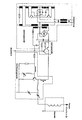
- Eine Einrichtung nach der Erfindung ist als Schaltbild dargestellt. Eingesetzt als Zündeinrichtung für einen Verbrennungsmotor eines Kraftfahrzeuges beispielsweise wird ein Spannungswandler mit der Bordspannung des Bordnetzes versorgt. Der Spannungswandler liefert die Energie für einen angeschlossenen Hochfrequenzgenerator, der seinerseits über einen Leistungsschalter geschaltet wird. Am Hochfrequenzgenerator angeschlossen ist eine Elektrode, die wie eine Zündkerze in den Verbrennungsraum des Motors hineinragt, wobei direkt auf die Elektrode ein Resonator aufgesetzt ist. Dies ist erforderlich, weil ein Kabelanschluß am Ausgang des Resonators nicht möglich ist, da an dieser Stelle so hohe Feldstärke herrscht, daß dort das Plasma entstehen würde. Um ein Plasma entstehen zu lassen, wird der Hochfrequenzgenerator vom Leistungsschalter eingeschaltet, wobei der Leistungsschalter einen Stuefimpuls erhält z. B. von der Einrichtung der Maschine, die auch bisher den Impuls für die Zündung gegeben hat.
- Es ist zur Erreichung eines günstigen Wirkungsgrades günstig, den Hochfrequenzgenerator mit hoher Spannung zu betrieben, weil hierdurch einerseits die Verlustwärme verringert wird und hierdurch andererseits eine höhere Hochfrequenz-Ausgangsspannung am Ausgang des Generators erreicht wird, die ja durch den Resonator auf noch höhere Werte transformiert werden muß. Hierbei setzt der Spannungswandler die ja meist niedrigere Bordspannung auf höhere Werte hinauf. Im dargestellten Fall handelt es sich um einen frei schwingenden Gegentacktwandler.
- Um den Lesitungsbedarf gering zu halten, wird diese Gleichspannung dem Hochfrequenzgenerator nur im Moment der Zündung zugeführt. Dies übernimmt ein Leistungstransistor (Leistungsschalter in der Darstellung), der von einem Steuerimpuls geschaltet wird. Der Steuerimpuls kommt von der bereits im Kraftfahrzeug für die herkömmliche Zündung enthaltenen Einrichtung.
- Der Hochfrequenzgenerator arbeitet als Leistungsoszylator. Er läßt sich so konstruieren, daß er selbst die Leistung durch erhöhte Mittkopplung im nicht angepaßten Lastfall (kurz bevor das Plasma zündet) erhöht und somit die Plasmazündung beschleunigt. Diese aus dem Hochfrequenzgenerator gewonnene Ausgangsspannung reicht jedoch nicht aus, um die Ionisation in Gang zu setzen. Der nachgeschaltet Resonator übernimmt daher die Aufgabe, diese Spannung auf den notwendigen hohen Pegel zu bringen. Dazu muß der Resonator eine hohe Güte aufweisen. Es ist hierbei zu beachten, daß die Größe eines Resonators mit höher werdender Frequenz kleiner wird. Wird also ein kleiner Resonator angestrebt, so muß mit hoher Frequenz gearbeitet werden.
- Zur besseren Verständlichkeit des Schaltbildes sind dort einzelne Bauelemente mit Bezugszahlen versehen, wobei in der beigefügten Bezugszahlenliste die Bennung der entsprechenden Bauteile aufgeführt ist.
-
- 1 Entstördrossel
- 2 Ansteuertrafo für Spannungswandler
- 3 Leistungstrafo vom Spannungswandler
- 4 Schalttransistoren vom Spannungswandler
- 5 Schalttransistoren vom Spannungswandler
- 6 Gleichrichter
- 7 Schalttransistoren, die den Hochfrequenz generator einschalten
- 8 Hochfrequenzleistungstransistor
- 9 Drehkondensator (dient zur Anpassung)
- 10 Hochfrequenz-Drossel
Claims (6)
Priority Applications (1)
| Application Number | Priority Date | Filing Date | Title |
|---|---|---|---|
| AT86102234T ATE53894T1 (de) | 1985-07-27 | 1986-02-20 | Verfahren zur einbringung thermischer energie in einen mit einem medium gefuellten raum und einrichtung hierzu. |
Applications Claiming Priority (2)
| Application Number | Priority Date | Filing Date | Title |
|---|---|---|---|
| DE3527041 | 1985-07-27 | ||
| DE19853527041 DE3527041A1 (de) | 1985-07-27 | 1985-07-27 | Verfahren zur einbringung thermischer energie in einen mit einem medium gefuellten raum und einrichtung hierzu |
Publications (2)
| Publication Number | Publication Date |
|---|---|
| EP0211133A1 EP0211133A1 (de) | 1987-02-25 |
| EP0211133B1 true EP0211133B1 (de) | 1990-05-02 |
Family
ID=6277024
Family Applications (1)
| Application Number | Title | Priority Date | Filing Date |
|---|---|---|---|
| EP86102234A Expired - Lifetime EP0211133B1 (de) | 1985-07-27 | 1986-02-20 | Verfahren zur Einbringung thermischer Energie in einen mit einem Medium gefüllten Raum und Einrichtung hierzu |
Country Status (3)
| Country | Link |
|---|---|
| EP (1) | EP0211133B1 (de) |
| AT (1) | ATE53894T1 (de) |
| DE (2) | DE3527041A1 (de) |
Cited By (7)
| Publication number | Priority date | Publication date | Assignee | Title |
|---|---|---|---|---|
| US5499304A (en) * | 1990-10-02 | 1996-03-12 | Delco Electronics Corporation | Light mask |
| DE19747700A1 (de) * | 1997-10-29 | 1999-05-12 | Volkswagen Ag | Zündkerze für Plasmastrahl-Zündeinrichtung |
| DE19747701A1 (de) * | 1997-10-29 | 1999-05-12 | Volkswagen Ag | Plasmastrahl-Zündung für Verbrennungskraftmaschinen |
| EP1215392A2 (de) | 2000-12-12 | 2002-06-19 | Volkswagen AG | Element und Vorrichtung zur Energieeinkopplung in einen mit einem bestimmten Medium gefüllten Raum |
| EP1588048A1 (de) | 2003-01-06 | 2005-10-26 | Paul Douglas Freen | System und verfahren zur erzeugung und aufrechterhaltung einer elektrischen koronaentladung zum zünden eines brennbaren gasgemisches |
| EP2012004A1 (de) | 2007-07-03 | 2009-01-07 | Delphi Technologies, Inc. | Hochfrequenzzündeinrichtung und Verfahren zu deren Betrieb |
| DE10143194B4 (de) * | 2001-09-04 | 2013-02-07 | Volkswagen Ag | Hochfrequenzzündung für Verbrennungskraftmaschinen |
Families Citing this family (12)
| Publication number | Priority date | Publication date | Assignee | Title |
|---|---|---|---|---|
| DD261289A3 (de) * | 1986-11-11 | 1988-10-26 | Freiberg Brennstoffinst | Einrichtung zur kombinierten zuendung und ueberwachung von brennern |
| DD261290A3 (de) * | 1986-11-11 | 1988-10-26 | Freiberg Brennstoffinst | Kombinierte zuend- und ueberwachungseinrichtung fuer brenner |
| DE19644514A1 (de) * | 1996-10-25 | 1998-04-30 | Pinkalla Reiner | Zündanlage für Brennstoffmotoren |
| DE19723784C1 (de) * | 1997-06-06 | 1998-08-20 | Daimler Benz Ag | Schaltungsanordnung für die Zündung einer Brennkraftmaschine |
| DE19852652A1 (de) * | 1998-11-16 | 2000-05-18 | Bosch Gmbh Robert | Zündvorrichtung für Hochfrequenz-Zündung |
| DE10157029A1 (de) * | 2001-11-21 | 2003-06-05 | Bosch Gmbh Robert | Hochfrequenzzündung für eine Brennkraftmaschine |
| DE10239410B4 (de) * | 2002-08-28 | 2004-12-09 | Robert Bosch Gmbh | Vorrichtung zum Zünden eines Luft-Kraftstoff-Gemischs in einem Verbrennungsmotor |
| DE10243271A1 (de) * | 2002-09-18 | 2003-12-04 | Bosch Gmbh Robert | Vorrichtung zum Zünden eines Luft-Kraftstoff-Gemischs in einem Verbrennungsmotor |
| DE102005036968A1 (de) | 2005-08-05 | 2007-02-15 | Siemens Ag | Plasma-Zündsystem und Verfahren zu dessen Betrieb |
| CN101679885B (zh) | 2008-01-28 | 2013-03-27 | 国际壳牌研究有限公司 | 启动煤气化反应器的方法 |
| DE102009013877A1 (de) * | 2009-03-16 | 2010-09-23 | Beru Ag | Verfahren und System zum Zünden eines Brennstoff-Luft-Gemisches einer Verbrennungskammer, insbesondere in einem Verbrennungsmotor durch Erzeugen einer Korona-Entladung |
| CN102777928A (zh) * | 2012-07-30 | 2012-11-14 | 咸阳西燃机电设备有限公司 | 小功率等离子点火电路及装置 |
Family Cites Families (8)
| Publication number | Priority date | Publication date | Assignee | Title |
|---|---|---|---|---|
| US2617841A (en) * | 1949-01-03 | 1952-11-11 | Rca Corp | Internal-combustion engine ignition |
| US4138980A (en) | 1974-08-12 | 1979-02-13 | Ward Michael A V | System for improving combustion in an internal combustion engine |
| DE2611596C2 (de) * | 1976-03-19 | 1985-06-20 | Robert Bosch Gmbh, 7000 Stuttgart | Verfahren und Vorrichtung zur Erzeugung von Zündfunken bei hohem Zündspannungsbedarf für Zündanlagen von Brennkraftmaschinen |
| US4122816A (en) * | 1976-04-01 | 1978-10-31 | The United States Of America As Represented By The Administrator Of The National Aeronautics And Space Administration | Plasma igniter for internal combustion engine |
| US4297983A (en) * | 1978-12-11 | 1981-11-03 | Ward Michael A V | Spherical reentrant chamber |
| JPS57113968A (en) | 1981-01-07 | 1982-07-15 | Hitachi Ltd | Microwave plasma ignition type engine |
| JPS57206776A (en) * | 1981-06-16 | 1982-12-18 | Nissan Motor Co Ltd | Plasma ignition device |
| JPS59168270A (ja) * | 1983-03-12 | 1984-09-21 | Fuji Heavy Ind Ltd | 点火時期制御装置 |
-
1985
- 1985-07-27 DE DE19853527041 patent/DE3527041A1/de not_active Withdrawn
-
1986
- 1986-02-20 AT AT86102234T patent/ATE53894T1/de not_active IP Right Cessation
- 1986-02-20 EP EP86102234A patent/EP0211133B1/de not_active Expired - Lifetime
- 1986-02-20 DE DE8686102234T patent/DE3670887D1/de not_active Expired - Lifetime
Cited By (11)
| Publication number | Priority date | Publication date | Assignee | Title |
|---|---|---|---|---|
| US5499304A (en) * | 1990-10-02 | 1996-03-12 | Delco Electronics Corporation | Light mask |
| DE19747700A1 (de) * | 1997-10-29 | 1999-05-12 | Volkswagen Ag | Zündkerze für Plasmastrahl-Zündeinrichtung |
| DE19747701A1 (de) * | 1997-10-29 | 1999-05-12 | Volkswagen Ag | Plasmastrahl-Zündung für Verbrennungskraftmaschinen |
| DE19747701C2 (de) * | 1997-10-29 | 1999-12-23 | Volkswagen Ag | Plasmastrahl-Zündung für Verbrennungskraftmaschinen |
| DE19747700C2 (de) * | 1997-10-29 | 2000-06-29 | Volkswagen Ag | Zündeinrichtung mit einer Zündelektrode |
| EP1215392A2 (de) | 2000-12-12 | 2002-06-19 | Volkswagen AG | Element und Vorrichtung zur Energieeinkopplung in einen mit einem bestimmten Medium gefüllten Raum |
| DE10143194B4 (de) * | 2001-09-04 | 2013-02-07 | Volkswagen Ag | Hochfrequenzzündung für Verbrennungskraftmaschinen |
| EP1588048A1 (de) | 2003-01-06 | 2005-10-26 | Paul Douglas Freen | System und verfahren zur erzeugung und aufrechterhaltung einer elektrischen koronaentladung zum zünden eines brennbaren gasgemisches |
| EP2067986A3 (de) * | 2003-01-06 | 2009-10-21 | BorgWarner, Inc. | System und Verfahren zur Erzeugung und Aufrechterhaltung einer elektrischen Koronaentladung zum Zünden eines brennbaren Gasgemisches |
| EP1588048B1 (de) * | 2003-01-06 | 2010-11-03 | BorgWarner, Inc. | System und verfahren zur erzeugung und aufrechterhaltung einer elektrischen koronaentladung zum zünden eines brennbaren gasgemisches |
| EP2012004A1 (de) | 2007-07-03 | 2009-01-07 | Delphi Technologies, Inc. | Hochfrequenzzündeinrichtung und Verfahren zu deren Betrieb |
Also Published As
| Publication number | Publication date |
|---|---|
| DE3527041A1 (de) | 1987-02-05 |
| DE3670887D1 (de) | 1990-06-07 |
| EP0211133A1 (de) | 1987-02-25 |
| ATE53894T1 (de) | 1990-06-15 |
Similar Documents
| Publication | Publication Date | Title |
|---|---|---|
| EP0211133B1 (de) | Verfahren zur Einbringung thermischer Energie in einen mit einem Medium gefüllten Raum und Einrichtung hierzu | |
| DE60030121T2 (de) | Zwei-mode zündsystem, das reisenden funken zünder verwendet | |
| DE2535960A1 (de) | Brennkraftmaschinen-zuendanlage | |
| EP1697634B1 (de) | Verfahren zum zünden der verbrennung eines kraftstoffes in einem verbrennungsraum eines motors, zugehörige vorrichtung und motor | |
| DE2444242A1 (de) | Zuendsystem fuer eine innenverbrennungsmaschine | |
| DE2340865B2 (de) | Zündvorrichtung für eine Brennkraftmaschine | |
| DE60026841T2 (de) | Zündkerze mit vorwärtstreibendem funken und langer lebensdauer und zugehörige zündschaltung | |
| DE102005036968A1 (de) | Plasma-Zündsystem und Verfahren zu dessen Betrieb | |
| EP3636916A1 (de) | Zündsystem mit einem durch ein hf-plasma vergrösserten zündfunken einer zündkerze mit einer vorkammer sowie ein zugehöriges verfahren | |
| DE10037536C2 (de) | Verfahren und Vorrichtung einer Plasmazündung in Verbrennungsmotoren | |
| EP1299630A1 (de) | Zündverfahren und entsprechende zündvorrichtung | |
| EP0489747B1 (de) | Schaltungsanordnung zum betrieb einer gasentladungslampe | |
| DE102010045174A1 (de) | Schaltungsanordnung für eine HF-Zündung von Verbrennungsmotoren | |
| WO2017167437A1 (de) | Zündvorrichtung zum zünden eines luft-kraftstoffgemisches in einem brennraum | |
| DE2145089C3 (de) | Kondensatorzündanlage für Brennkraftmaschinen | |
| WO1994007027A1 (de) | Methode und system zur kontrolle der zündfunkenfrequenz eines vielfachfunkenzündsystems | |
| EP3436686B1 (de) | Zündvorrichtung zum zünden eines luft-kraftstoffgemisches in einem brennraum | |
| DE2543125A1 (de) | Verfahren und vorrichtung zum zuenden von kraftstoff/luft-gemischen in ottomotoren | |
| EP1924770A1 (de) | Verfahren und vorrichtung zum entzünden eines brennbaren gasgemisches in einem verbrennungsmotor | |
| DE102012210198B4 (de) | Zündvorrichtung | |
| DE1751892C3 (de) | Elektrische Impulserzeugungseinrichtung | |
| DE2646446A1 (de) | Brennkraftmaschinen-zuendanlage | |
| DE10231511A1 (de) | Zündspulensystem mit wenigstens zwei induktiven Spulen | |
| DE102018124761B4 (de) | Vorrichtung und Verfahren zur Zündung eines Brennstoffgemisches im Brennraum einer Brennkraftmaschine | |
| DE10015613A1 (de) | Zündanlage |
Legal Events
| Date | Code | Title | Description |
|---|---|---|---|
| PUAI | Public reference made under article 153(3) epc to a published international application that has entered the european phase |
Free format text: ORIGINAL CODE: 0009012 |
|
| AK | Designated contracting states |
Kind code of ref document: A1 Designated state(s): AT BE CH DE FR GB IT LI LU NL SE |
|
| 17P | Request for examination filed |
Effective date: 19870619 |
|
| 17Q | First examination report despatched |
Effective date: 19880722 |
|
| GRAA | (expected) grant |
Free format text: ORIGINAL CODE: 0009210 |
|
| AK | Designated contracting states |
Kind code of ref document: B1 Designated state(s): AT BE CH DE FR GB IT LI LU NL SE |
|
| REF | Corresponds to: |
Ref document number: 53894 Country of ref document: AT Date of ref document: 19900615 Kind code of ref document: T |
|
| ITF | It: translation for a ep patent filed | ||
| GBT | Gb: translation of ep patent filed (gb section 77(6)(a)/1977) | ||
| REF | Corresponds to: |
Ref document number: 3670887 Country of ref document: DE Date of ref document: 19900607 |
|
| ET | Fr: translation filed | ||
| PLBE | No opposition filed within time limit |
Free format text: ORIGINAL CODE: 0009261 |
|
| STAA | Information on the status of an ep patent application or granted ep patent |
Free format text: STATUS: NO OPPOSITION FILED WITHIN TIME LIMIT |
|
| 26N | No opposition filed | ||
| EPTA | Lu: last paid annual fee | ||
| EAL | Se: european patent in force in sweden |
Ref document number: 86102234.1 |
|
| PGFP | Annual fee paid to national office [announced via postgrant information from national office to epo] |
Ref country code: GB Payment date: 20010122 Year of fee payment: 16 |
|
| PGFP | Annual fee paid to national office [announced via postgrant information from national office to epo] |
Ref country code: AT Payment date: 20010220 Year of fee payment: 16 |
|
| PGFP | Annual fee paid to national office [announced via postgrant information from national office to epo] |
Ref country code: SE Payment date: 20010221 Year of fee payment: 16 |
|
| PGFP | Annual fee paid to national office [announced via postgrant information from national office to epo] |
Ref country code: FR Payment date: 20010222 Year of fee payment: 16 Ref country code: BE Payment date: 20010222 Year of fee payment: 16 |
|
| PGFP | Annual fee paid to national office [announced via postgrant information from national office to epo] |
Ref country code: LU Payment date: 20010223 Year of fee payment: 16 |
|
| PGFP | Annual fee paid to national office [announced via postgrant information from national office to epo] |
Ref country code: NL Payment date: 20010227 Year of fee payment: 16 |
|
| REG | Reference to a national code |
Ref country code: GB Ref legal event code: IF02 |
|
| PG25 | Lapsed in a contracting state [announced via postgrant information from national office to epo] |
Ref country code: LU Free format text: LAPSE BECAUSE OF NON-PAYMENT OF DUE FEES Effective date: 20020220 Ref country code: GB Free format text: LAPSE BECAUSE OF NON-PAYMENT OF DUE FEES Effective date: 20020220 Ref country code: AT Free format text: LAPSE BECAUSE OF NON-PAYMENT OF DUE FEES Effective date: 20020220 |
|
| PG25 | Lapsed in a contracting state [announced via postgrant information from national office to epo] |
Ref country code: SE Free format text: LAPSE BECAUSE OF NON-PAYMENT OF DUE FEES Effective date: 20020221 |
|
| PG25 | Lapsed in a contracting state [announced via postgrant information from national office to epo] |
Ref country code: BE Free format text: LAPSE BECAUSE OF NON-PAYMENT OF DUE FEES Effective date: 20020228 |
|
| BERE | Be: lapsed |
Owner name: HOLZ BERND Effective date: 20020228 |
|
| PG25 | Lapsed in a contracting state [announced via postgrant information from national office to epo] |
Ref country code: NL Free format text: LAPSE BECAUSE OF NON-PAYMENT OF DUE FEES Effective date: 20020901 |
|
| EUG | Se: european patent has lapsed |
Ref document number: 86102234.1 |
|
| GBPC | Gb: european patent ceased through non-payment of renewal fee |
Effective date: 20020220 |
|
| PG25 | Lapsed in a contracting state [announced via postgrant information from national office to epo] |
Ref country code: FR Free format text: LAPSE BECAUSE OF NON-PAYMENT OF DUE FEES Effective date: 20021031 |
|
| NLV4 | Nl: lapsed or anulled due to non-payment of the annual fee |
Effective date: 20020901 |
|
| REG | Reference to a national code |
Ref country code: FR Ref legal event code: ST |
|
| PGFP | Annual fee paid to national office [announced via postgrant information from national office to epo] |
Ref country code: CH Payment date: 20030304 Year of fee payment: 18 |
|
| PGFP | Annual fee paid to national office [announced via postgrant information from national office to epo] |
Ref country code: DE Payment date: 20030327 Year of fee payment: 18 |
|
| PG25 | Lapsed in a contracting state [announced via postgrant information from national office to epo] |
Ref country code: LI Free format text: LAPSE BECAUSE OF NON-PAYMENT OF DUE FEES Effective date: 20040229 Ref country code: CH Free format text: LAPSE BECAUSE OF NON-PAYMENT OF DUE FEES Effective date: 20040229 |
|
| PG25 | Lapsed in a contracting state [announced via postgrant information from national office to epo] |
Ref country code: DE Free format text: LAPSE BECAUSE OF NON-PAYMENT OF DUE FEES Effective date: 20040901 |
|
| REG | Reference to a national code |
Ref country code: CH Ref legal event code: PL |
|
| PG25 | Lapsed in a contracting state [announced via postgrant information from national office to epo] |
Ref country code: IT Free format text: LAPSE BECAUSE OF NON-PAYMENT OF DUE FEES Effective date: 20050220 |