US2617841A - Internal-combustion engine ignition - Google Patents
Internal-combustion engine ignition Download PDFInfo
- Publication number
- US2617841A US2617841A US68798A US6879849A US2617841A US 2617841 A US2617841 A US 2617841A US 68798 A US68798 A US 68798A US 6879849 A US6879849 A US 6879849A US 2617841 A US2617841 A US 2617841A
- Authority
- US
- United States
- Prior art keywords
- spark
- cavity resonator
- chamber
- piston
- gap
- Prior art date
- Legal status (The legal status is an assumption and is not a legal conclusion. Google has not performed a legal analysis and makes no representation as to the accuracy of the status listed.)
- Expired - Lifetime
Links
- 238000002485 combustion reaction Methods 0.000 title description 42
- 238000010304 firing Methods 0.000 description 13
- 239000000523 sample Substances 0.000 description 13
- 230000005540 biological transmission Effects 0.000 description 11
- 230000033001 locomotion Effects 0.000 description 11
- 239000004020 conductor Substances 0.000 description 9
- 239000007789 gas Substances 0.000 description 6
- 230000006835 compression Effects 0.000 description 5
- 238000007906 compression Methods 0.000 description 5
- 230000008878 coupling Effects 0.000 description 5
- 238000010168 coupling process Methods 0.000 description 5
- 238000005859 coupling reaction Methods 0.000 description 5
- 230000003247 decreasing effect Effects 0.000 description 3
- 230000005284 excitation Effects 0.000 description 3
- 230000010355 oscillation Effects 0.000 description 3
- 230000004075 alteration Effects 0.000 description 2
- 238000013459 approach Methods 0.000 description 2
- 238000004891 communication Methods 0.000 description 2
- 239000003566 sealing material Substances 0.000 description 2
- 235000003197 Byrsonima crassifolia Nutrition 0.000 description 1
- 240000001546 Byrsonima crassifolia Species 0.000 description 1
- OKTJSMMVPCPJKN-UHFFFAOYSA-N Carbon Chemical compound [C] OKTJSMMVPCPJKN-UHFFFAOYSA-N 0.000 description 1
- 241000282326 Felis catus Species 0.000 description 1
- 230000002411 adverse Effects 0.000 description 1
- 229910052799 carbon Inorganic materials 0.000 description 1
- 230000015556 catabolic process Effects 0.000 description 1
- 238000010276 construction Methods 0.000 description 1
- 230000001419 dependent effect Effects 0.000 description 1
- 238000013461 design Methods 0.000 description 1
- 239000003989 dielectric material Substances 0.000 description 1
- 230000000694 effects Effects 0.000 description 1
- 230000005684 electric field Effects 0.000 description 1
- 239000000463 material Substances 0.000 description 1
- 238000000034 method Methods 0.000 description 1
- 239000000203 mixture Substances 0.000 description 1
- 238000012552 review Methods 0.000 description 1
- 238000007789 sealing Methods 0.000 description 1
Images
Classifications
-
- F—MECHANICAL ENGINEERING; LIGHTING; HEATING; WEAPONS; BLASTING
- F02—COMBUSTION ENGINES; HOT-GAS OR COMBUSTION-PRODUCT ENGINE PLANTS
- F02P—IGNITION, OTHER THAN COMPRESSION IGNITION, FOR INTERNAL-COMBUSTION ENGINES; TESTING OF IGNITION TIMING IN COMPRESSION-IGNITION ENGINES
- F02P23/00—Other ignition
- F02P23/04—Other physical ignition means, e.g. using laser rays
- F02P23/045—Other physical ignition means, e.g. using laser rays using electromagnetic microwaves
Definitions
- the resonant circuit may comprise a cavity resonator having a movable tuning element directly connected to a piston of the chamber.
- part of the combustion chamber walls are the walls of the cavity resonator, and, moreover, the chamber and resonator walls may be the same.
- a further feature of the invention recognizes that there is an optimum sparking frequency for a spark-gap through a gas mixture. Therefore, I provide tuning of the generator and tuning and timing of the resonator so that not only does the sparking occur in the proper timed relationship, but also at the optimum frequency to assure an ample firing spark.
- the exhaust valve is placed to lower appreciably the cavity resonator Q.
- the opening of a valve may so affect th tuning of the cavity resonator comprising at least a portion of the combustion chamber that no two combustion chambers can be sparked at the same time.
- Cavity resonator 26 includes a movable tuning element, the piston-like wall member 28.
- Resonator 2B is also coupled to transmission line 36 the central conductor 32 of which terminates at the wall l2 connected to the outer conductor 34 of line 30 through wall Hi of combustion chamber lEl.
- Conductor 32 passes through wall i l through an insulating seal of dielectric material 36 which closes the chamber IE! against loss of compression at the entry of conductor 32.
- Conductor 32 has, however, a gap 3% which is the spark-gap of the ignition system for combustion chamber 10.
- Pistons l8 and 28 are linked by a mechanical coupling or linkage 43 which brings both pistons to a predetermined position relative to each other on the fillllg stroke of the piston.
- the high-frequency source 20 may be actuated by a distributor arrangement which, however, in accordance with the invention, then serves an entirely different function from that of the usual distributor arrangement.
- the usual distributor arrangement may be entirely omitted to advantage as will appear more clearly hereinafter.
- high frequency source 20 is excited to supply high-frequency energy to cavity resonator 26.
- the energy thus supplied is thereby coupled to line 30 through the cavity resonator 26.
- the amount of energy thus coupled to line 38 depends on the tuning of resonator 26 and is a maximum when the cavity resonator is tuned to the frequency of the highfrequency source 28.
- source 29 may, if desired, include buffer stages or other isolating means, to prevent the cavity resonator from shifting the frequency thereof to any appreciable degree.
- the travel of piston 23 may be adjusted so that the cavity resonator is tuned substantially to the frequency of source 20 at the moment when a spark is desired at spark-gap 38.
- the amount of energy supplied the resonator 25 is then adjusted so that sparking is effected when the point of resonance is reached.
- the source 20 may be adjusted in frequency to provide an adjustment of the time of sparking in relation to the time of travel of piston [8 of chamber Iii, so that adjustment by means of adjusting the relative movements of the piston l8 and piston-like member 28 may be dispensed with.
- the Q of cavity resonators such as resonator 26 may be made exceedingly high, say of the order of 10 to 20 thousand.
- the frequency to which the resonator is tuned is thus sharply and definitely dependent on the position of tuning member 28.
- the point of travel of tuning member 28 at which the spark will jump across spark-gap 38 may be determined with great definitude and sharpness with respect to the position of piston l8.
- a further refinement of th invention may be effected by causing chamber 10 itself to become electromagnetically resonant at the desired frequency at the desired point of its travel for sparking.
- the field strength built up to break down the spark-gap 38 across the terminals of conductor 32 defining th spark-gap is thereby increased at resonance. This may be accomplished, for example, by suitably relating the sizes of cavity resonator 26 and chamber H] to be of the same size if they are excited in the same mode of oscillation.
- the modes of oscillation chosen are preferably those which minimize currents between the fixed and movable walls of the cavity resonator or resonators to avoid the lowering of the Q and the requirement of good electrical contact at high frequencies between the walls movable with respect to each other.
- the cavity resonator walls may be of high conductivity,'for example, silverplated.
- a cavity resonator 50 is coupled to the oscillator 28 through transmission line 24 sealed into the engine wall I l shown enlarged to make room for the cavity resonator.
- the cavity resonator 5B is coupled to the combustion chamber In by transmission line 30 which passes through wall M in this case.
- the central conductor 32 of line 39 may be supported by means well known which may provide free communication for gases between cavity resonator 50 and chamber I0. Thus differential pressures are avoided. However, such free communication may be prevented if access of gases to resonator 50 may adversely effect wall conductivity.
- Projection .52 may form only a loosefit withthe side wallsojlthelhollowed portion if the mode of oscillation is properly chosen, for example, to be the TEou mode 'having .circular electric lines of force and excel tionallyhigh Q'.
- the direct electrica'l contact of projection 52 with the ,-side-walls or cavity resonator 50. becomes unimportant.
- the dimensions of cavity resonator 50 maybe chosen toproviderthe desired resonance at the desired-point of travel at'a frequencyto conform to the optimum sparking frequency for thegaseouscombustionmixture in chamber Ill. That there are such. optimum frequencies is evidenced by the article by Herlin and Brown in the Physical Review, vol.
- Fig.2 has the advantage that no separate 'gearing or mechanical linkages are required, since the tuning member of cavity resonator 50, in this instance the projection 52, is directly connected mechanically to the. movable wall member of combustion chamber l'll that is, to-theypiston l8.
- Fig. 3 is a cross-sectional view of an embodiment of the invention similar insome respects to thatof'Fig. 2, the'cavity resonator 50 is not coupled through a-separate transmission line to oombustionchamber. it, but .i's-itself an auxiliary combustion chamber.
- Cavityresonator 50 is preferablyexcited in the dominant .TM' mode, in which eventa strongelectric field is created between the, central portions 56 'and 58 of the circular end walls respectivelyof the .cylindrically shaped resonator. Central' portions 56; and 58 then become the terminalsof a spark-gap which is the space between them.
- Fig. :4 is a cross-sectional view of an embodiment of .tlie inventiondnwhich cavity resonatortai and combustion chamber -l I] have-identical walls.
- onaXial transmission line"24 is coupled to thecavi'ty resonatorby a coupling loop 'lll.
- the centralcondoctor. is .passed through dielectric I sealing material "12.
- the central conductor may be omitted, the outer conductor of transmission line .24 having suitable dimensions to act as .a waveguide'transmission line andappropriate coupling means then being; substituted for coupling loop T0 and-the dis electric sealing material sealing .the aperturelin Wall 12 leading to the waveguide.
- allcombustion chambers may be resonated byadjustment of screw 16 at the-corresponding positions of piston t8, after which the timing of the sparking may beeffected by frequency contro1dial22 for theengine as a whole. This result may be reached wherever the cavity resonator may be tuned separately from the moving tuning member.
- combustion chamber] 0 is again identical with cavity resonator 68.
- the construction and operation is similar to the arrangement of 4, except that there is no screw 16.
- a capacitive projection 86 is attached to the wall l'd of chamber In.
- capacitive projection 80 which may be cylindrical as shown, there is a pointed metallic probe 82' projecting centrally thereof which tends to increase the gradient of the electric-field inthe vicinity of thepoint and across the sparkgap'84 (as seen in 'Fig. 7") of which probe'82 is one terminal.
- the other terminal of spark-gap '84 is.
- Loop 86 is arranged in such a manner that 'in' the sparking position of the ,parts as illustrated bythe partial cross sectional view of Figs;6 and 7, the probe 8'2 and loop 86. are substantially'spaced equaldistances from 'eachother throughout the time of travel of piston 1'8 durin'gwhich thecavity res onator 6E (identical with combustion chamber 1:0) approaches,:and'recedes with the travel 01' piston ['8 from "itsfcondition of resonance.
- the purpose of thecapacitive projection-.88 which'is incapaciti-ve relationship particularly with piston I8 is to cause the capacity between the "end walls OfiCSzVltY resonator 68 tochange withg-reat- -er rapidity with the motion 'of piston l8- than would be :the case were the projection 89 absent. Therefore, the frequency of resonance changes with greater rrapidity with motion of-piston l8, and consequently the position of the piston at which sparking occurs across spark-gap 84 fora definite frequency of source 20 is defined with greater accuracy.
- FIG. 8 is a cross-sectional view of an embodiment of the invention.
- Combustion chamber I and the cavity of cavity resonator 68 occupy the same space.
- a plate I00, having considerable capacity with piston I8, is adjustable by a screw H12. Screw It, with a pointed probe end, similar to screw 16 of Fig. 4 but differently placed, is also threaded through wall [4. The probe may be adjusted for a desired spark-gap spacing and serves as one terminal defining the spark-gap and being coupled to cavity resonator 68 through the. walls thereof.
- the other terminal of the spark-gap is a portion of the cavity resonator wall formed by piston l8.
- Capacitive plate 100 may be adjusted to give sparking at a desired frequency, the probe being adjusted for a desired spark-gap length.
- the probe increases the field gradient across the spark-gap.
- the position of the probe screw 16 is determined largely by the field configuration of the mode of excitation of cavity resonator (i8. As understood by those skilled in the cavity resonator art, there may well be more than one preferred position among which a choice may be made as desired.
- a different adjustment of plate N39 is required to resonate cavity resonator 68 at a desired frequency.
- Source 2i! may be adjusted in frequency to cause sparking at a desired point in the engine cycle.
- a distributor system may or may not play in the practice of the invention.
- a distributor in the ordinary sense is not required.
- a distributor may be used, if so desired, particularly in multi-cylinder four-cycle engines, to provide energy to a particular combustion chamber of such an engine only during an interval of time which starts immediately before and ends after the time at which sparking is to occur.
- sparking energy is applied at the precise time or instant that firing of the spark gap is desired.
- energy is applied by means of a permanent connection such as coaxial line 24 of Fig.
- valve head 92 will be in a closed position, if the engine is of the customary four-cycle multi-piston type.
- the combustion chamber is having valve head 92 closed, however, will have a comparatively high Q and accordingly the energy from source 29 which may be coupled simultaneously to all the cavity resonators 68 (and chamber [0) of the multicylinder engine, will cause a spark only in the spark-gap il of the high Q chamber, assuming that the spark-gaps are appropriately adjusted.
- the transmission line it in such an arrangement may be appropriately branched with a branch 94, for example, to lead to other combustion chambers, only one such branch being shown in Figure 8.
- the firing chamber is fired twice, once by a spark at the usual time a few degrees before the piston reaches the top of its travel, and again as it is making the power stroke, when it again passes the critical position of resonance. However, it does not fire on the exhaust stroke when the exhaust port is open.
- valve head 92 acts also as a capacitive projection which, at the time the port is open, tunes the resonator to a different frequency.
- the detuning may be made sufficiently great, as by an added projection on the valve head 92, that the sparking in chamber 68 across spark-gap 84 occurs at a different time from the sparking with the port 90 closed.
- the companion chamber is not fired at the same time. If, for example, a companion chamber timed to exhaust when piston l8 was making its compression stroke (and vice-versa) were sparked when chamber 68 was 11 combustion chamber and the cavity of said cavity resonator occupying the same space.
- said movable wall member being a piston and said cavity resonator having one of the cavity walls thereof defined by said piston.
- a high frequency circuit having a spark-gap in said chamber and comprising a cavity resonator having a tuning element movable in timed relation with the said engine member, means to apply high frequency energy to said circuit from a source of high frequency energy, continuously from before to the time at which the motion of said element tunes said chamber to the operating frequency of said source, whereby the precise time of firing of said spark-gap is determined by the position of said element, said chamber having a wall with a port therein closable by a closure, said wall with said port being also a Wall of said cavity resonator, said port being opened and closed by said closure in timed relation with said movable wall member and being positioned to decrease the Q of said chamber with the port open over the Q of said chamber with the port closed by said closure.
- a high frequency circuit having a spark-gap in said chamber and comprising a cavity resonator having a tuning element movable in timed relation with the said engine member, means to apply high frequency energy to said circuit from a source of high frequency energy, continuously from before to the time at which the motion of said element tunes said chamber to the operating frequency of said source, whereby the precise time of firing of said spark-gap is determined by the position of said element, said chamber having a wall with a port therein closable by a closure, said wall with said port being also a wall of said cavity resonator, said port being opened and closed by said closure in timed relation with said movable'wall member and being positioned to alter by its motion between open and closed positions the frequency of resonance of said resonator.
- a high-frequency circuit having a spark-gap in said chamber and comprising a cavity resonator the cavity of which occupies at least a portion of said chamber, said cavity resonator having a tuning element comprising s i 12 piston and the walls thereof having a projection in a position toward which and away from which said piston travels and said projection having a highly capacitive relation to said piston means to apply high frequency energy to said circuit from a source of high frequency energy, continuously from before to the time at which the motion of said element tunes said chamber to the operating frequency of said source, whereby the precise time of firing of said spark-gap is determined by the position of said element.
- a high frequency circuit having a spark-gap in said chamber defined by terminals at least one of which is a pointed probe and comprising a cavity resonator the cavity of which occupies at least part of the space of said chamber, said cavity resonator having a projection in a position from which and toward which said piston travels and said projection having a highly capacitive relation to said piston, said probe extending from said projection, said piston being a tuning element for said cavity resonator means to apply high frequency energy to said circuit from a source of high frequency energy, continuously from before to the time at which the motion of said element tunes said chamber to the operating frequency of said source, whereby the precise time of firing of said spark-gap is determined by the position of said element.
- a high-frequency circuit having a spark-gap in each of said chambers and comprising a plurality of resonators one for each chamber and each resonator having a tuning element movable in timed relation with said movable wall members, and a source of high-frequency energy coupled to each said resonator means to apply high frequency energy to said circuit from a source of high frequency energy, continuously from before to the time at which the motion of said element tunes said chamber to the operating frequency of said source, whereby the precise time of firing of said spark-gap is determined by the position of said element.
Landscapes
- Engineering & Computer Science (AREA)
- Physics & Mathematics (AREA)
- Optics & Photonics (AREA)
- Chemical & Material Sciences (AREA)
- Combustion & Propulsion (AREA)
- Mechanical Engineering (AREA)
- General Engineering & Computer Science (AREA)
- Electromagnetism (AREA)
- Combustion Methods Of Internal-Combustion Engines (AREA)
Description
w m mm F 7 I 1 M 0 MI E i W u i 4 II. n I 4 M 7% 1 m5 Mflflo. 2 2 M 1- E 1. E5 M a .,.w aw F z 1 me l'rngsl ATTORNEY E. G. LINDER Y INTERNAL-COMBUSTION ENGINE IGNITION Filed Jan. 3, 1949 nance of the resonator. In accordance witha further feature of the invention, the resonant circuit may comprise a cavity resonator having a movable tuning element directly connected to a piston of the chamber. In accordance with till another feature of the invention, part of the combustion chamber walls are the walls of the cavity resonator, and, moreover, the chamber and resonator walls may be the same. A further feature of the invention recognizes that there is an optimum sparking frequency for a spark-gap through a gas mixture. Therefore, I provide tuning of the generator and tuning and timing of the resonator so that not only does the sparking occur in the proper timed relationship, but also at the optimum frequency to assure an ample firing spark. In accordance with still a further feature of the invention, the exhaust valve is placed to lower appreciably the cavity resonator Q. Thus sparking when the exhaust valve is closed, which is the case in most engines during the compression and firing time of the cycle, is allowed, while sparking during the exhaust and intake cycles is efiectively inhibited. The sparking in one chamber, at a time when sparking is desired in another companion chamber might prevent the desired spark in that companion chamber at the proper time. Further, therefore, in accordance with another feature of the invention, the opening of a valve may so affect th tuning of the cavity resonator comprising at least a portion of the combustion chamber that no two combustion chambers can be sparked at the same time.
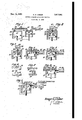
Referring now more particularly to Fig. 1, an
internal combustion engine has a cylindrical combustion chamber It with walls I2, [4, and E8, the latter wall 18 being movable and being the piston head of the engine. A showing of the ports and valves is omitted from the drawing wherever not required for a clear understanding of the invention. A high-frequency source of electrical energy 20 preferably of adjustable frequency, as by a dial 22, is coupled by a transmission line, in this instance shown as a coaxial transmission line 24, to a resonant circuit or resonator, in this instance cavity resonator 26. Cavity resonator 26 includes a movable tuning element, the piston-like wall member 28. Resonator 2B is also coupled to transmission line 36 the central conductor 32 of which terminates at the wall l2 connected to the outer conductor 34 of line 30 through wall Hi of combustion chamber lEl. Conductor 32 passes through wall i l through an insulating seal of dielectric material 36 which closes the chamber IE! against loss of compression at the entry of conductor 32. Conductor 32 has, however, a gap 3% which is the spark-gap of the ignition system for combustion chamber 10. Pistons l8 and 28 are linked by a mechanical coupling or linkage 43 which brings both pistons to a predetermined position relative to each other on the fillllg stroke of the piston. As will appear more fully hereinafter, the high-frequency source 20 may be actuated by a distributor arrangement which, however, in accordance with the invention, then serves an entirely different function from that of the usual distributor arrangement. On the other hand, the usual distributor arrangement may be entirely omitted to advantage as will appear more clearly hereinafter.
In operation, high frequency source 20 is excited to supply high-frequency energy to cavity resonator 26. The energy thus supplied is thereby coupled to line 30 through the cavity resonator 26. The amount of energy thus coupled to line 38 depends on the tuning of resonator 26 and is a maximum when the cavity resonator is tuned to the frequency of the highfrequency source 28. It will be understood that source 29 may, if desired, include buffer stages or other isolating means, to prevent the cavity resonator from shifting the frequency thereof to any appreciable degree. The travel of piston 23 may be adjusted so that the cavity resonator is tuned substantially to the frequency of source 20 at the moment when a spark is desired at spark-gap 38. The amount of energy supplied the resonator 25 is then adjusted so that sparking is effected when the point of resonance is reached. It will now be appreciated that the source 20 may be adjusted in frequency to provide an adjustment of the time of sparking in relation to the time of travel of piston [8 of chamber Iii, so that adjustment by means of adjusting the relative movements of the piston l8 and piston-like member 28 may be dispensed with. The Q of cavity resonators such as resonator 26 may be made exceedingly high, say of the order of 10 to 20 thousand. The frequency to which the resonator is tuned is thus sharply and definitely dependent on the position of tuning member 28. Hence the point of travel of tuning member 28 at which the spark will jump across spark-gap 38 may be determined with great definitude and sharpness with respect to the position of piston l8.
A further refinement of th invention may be effected by causing chamber 10 itself to become electromagnetically resonant at the desired frequency at the desired point of its travel for sparking. The field strength built up to break down the spark-gap 38 across the terminals of conductor 32 defining th spark-gap is thereby increased at resonance. This may be accomplished, for example, by suitably relating the sizes of cavity resonator 26 and chamber H] to be of the same size if they are excited in the same mode of oscillation. It will be understood by those skilled in the art that the modes of oscillation chosen are preferably those which minimize currents between the fixed and movable walls of the cavity resonator or resonators to avoid the lowering of the Q and the requirement of good electrical contact at high frequencies between the walls movable with respect to each other. The cavity resonator walls may be of high conductivity,'for example, silverplated. The arrangement of Fig. 1, just described, having a separate cavity resonator has theadvantage that carbon and other extraneous material does not deleteriously affect the high Q of this separate resonator. However, this arrangement does require a separate mechanical linkage.
Referring now more particularly to Fig. 2, a cavity resonator 50 is coupled to the oscillator 28 through transmission line 24 sealed into the engine wall I l shown enlarged to make room for the cavity resonator. The cavity resonator 5B is coupled to the combustion chamber In by transmission line 30 which passes through wall M in this case. The central conductor 32 of line 39 may be supported by means well known which may provide free communication for gases between cavity resonator 50 and chamber I0. Thus differential pressures are avoided. However, such free communication may be prevented if access of gases to resonator 50 may adversely effect wall conductivity. A central cylindrical saga;
projection llf tem piston l Bbifits. 'thefwaills" of cavity resonator 50 the cavity of whichIis hollowed Tout wan "I 4. Projection .52 may form only a loosefit withthe side wallsojlthelhollowed portion if the mode of oscillation is properly chosen, for example, to be the TEou mode 'having .circular electric lines of force and excel tionallyhigh Q'. Thus the direct electrica'l contact of projection 52 with the ,-side-walls or cavity resonator 50. becomes unimportant. The coupling of transmission line 34 to cavity resonator Ellis byaprobe 54.
Thearrangement of Fig,'2-operates in-amanner similarto that-of Fig. 1.. Source ZlImayQ-be tuned to determine the point'of travellof projection=52-at which the .sparkgap :38 fires, aswillbe clear'to those skilled inthe-art ofr-electronicsand cavity resonator-s. Further, the dimensions of cavity resonator 50 maybe chosen toproviderthe desired resonance at the desired-point of travel at'a frequencyto conform to the optimum sparking frequency for thegaseouscombustionmixture in chamber Ill. That there are such. optimum frequencies is evidenced by the article by Herlin and Brown in the Physical Review, vol. 74, page 2391' (1948), and one appropriate to a reasonably dimensioned cavity resonator 50 may readily be chosen, as a generalrule. The arrangement of Fig.2 has the advantage that no separate 'gearing or mechanical linkages are required, since the tuning member of cavity resonator 50, in this instance the projection 52, is directly connected mechanically to the. movable wall member of combustion chamber l'll that is, to-theypiston l8.
Referring now to Fig. 3, which is a cross-sectional view of an embodiment of the invention similar insome respects to thatof'Fig. 2, the'cavity resonator 50 is not coupled through a-separate transmission line to oombustionchamber. it, but .i's-itself an auxiliary combustion chamber. Cavityresonator 50 is preferablyexcited in the dominant .TM' mode, in which eventa strongelectric field is created between the, central portions 56 'and 58 of the circular end walls respectivelyof the .cylindrically shaped resonator. Central' portions 56; and 58 then become the terminalsof a spark-gap which is the space between them. These terminals andthe:spark-gapbetween them are obviously in circuit with the cavity resonator -50-,-being a part of ithewalls thereof. In thisembodiment -I prefer to add pointed metallic projections '6'4 and 6 6 which approach in .near contact witheach other at the time for sparking and which extend from central portions 56 and.58. The projections 56 and 58 :are then the terminals between which is the :spark-Igap. flhese projections 56 andfifi tend to increase the :fleldigradient 'in the spark-gap between them .and 'thereby'aid a break-down of the gas 'at resonance. Cavityres onator 50 and combustion chamber-Hircommunicate with each other freely, if not at the moment of firing, then shortly thereafter; injthe, engine cycle, depending on the design and-modeof-excitation .of cavityxresonator 50, the;compression ratios desired, and the; degree of electrical contact required between projection 52 and the side walls of cavity, resonatoriflv Thuscombustion occurs :in both chambers. Therefore, a portion of combustion chamber Ill] is identical -with cavity resonator. .58. Projection 52 may be "considered aipart-of the piston 48. Time of spa-rkingiinfrelation; to piston position again may be controlled by controlling-thefrequency of source 20. v I
Referring now more particularly to; Fig. :4, which is a cross-sectional view of an embodiment of .tlie inventiondnwhich cavity resonatortai and combustion chamber -l I] have-identical walls. onaXial transmission line"24 is coupled to thecavi'ty resonatorby a coupling loop 'lll. The centralcondoctor. is .passed through dielectric I sealing material "12. T11 .sufiic'ien'tly high frequencies are used, the central conductor may be omitted, the outer conductor of transmission line .24 having suitable dimensions to act as .a waveguide'transmission line andappropriate coupling means then being; substituted for coupling loop T0 and-the dis electric sealing material sealing .the aperturelin Wall 12 leading to the waveguide. "There is a spark gap l4;between the point of a-sc'rew 1-6 in wall! of chamber), and the central .portion of cylinder 13'. This permits adjustment of the gap with a .certain amount of tuning of the cat ity resonator. Timebf sparking may be controlled, as before, by adjustment of the frequency of source 20. Moreover, inamulti-cylinder engine, allcombustion chambers may be resonated byadjustment of screw 16 at the-corresponding positions of piston t8, after which the timing of the sparking may beeffected by frequency contro1dial22 for theengine as a whole. This result may be reached wherever the cavity resonator may be tuned separately from the moving tuning member.
Referring now more particularly to Figs. 15, 6 and '7 whichare respectively a cross-sectional view of still another embodiment of the invention and partial cross-sectional views thereof, combustion chamber] 0 is again identical with cavity resonator 68. The construction and operation is similar to the arrangement of 4, except that there is no screw 16. Instead, a capacitive projection 86 is attached to the wall l'd of chamber In. From capacitive projection 80; which may be cylindrical as shown, there is a pointed metallic probe 82' projecting centrally thereof which tends to increase the gradient of the electric-field inthe vicinity of thepoint and across the sparkgap'84 (as seen in 'Fig. 7") of which probe'82 is one terminal. The other terminal of spark-gap '84 is. a metallic "wire-like loop -86. Loop 86 is arranged in such a manner that 'in' the sparking position of the ,parts as illustrated bythe partial cross sectional view of Figs;6 and 7, the probe 8'2 and loop 86. are substantially'spaced equaldistances from 'eachother throughout the time of travel of piston 1'8 durin'gwhich thecavity res onator 6E (identical with combustion chamber 1:0) approaches,:and'recedes with the travel 01' piston ['8 from "itsfcondition of resonance. The purpose of thecapacitive projection-.88 which'is incapaciti-ve relationship particularly with piston I8 is to cause the capacity between the "end walls OfiCSzVltY resonator 68 tochange withg-reat- -er rapidity with the motion 'of piston l8- than would be :the case were the projection 89 absent. Therefore, the frequency of resonance changes with greater rrapidity with motion of-piston l8, and consequently the position of the piston at which sparking occurs across spark-gap 84 fora definite frequency of source 20 is defined with greater accuracy. The arrangement of probe 82 and wire 864s such that the spark-gapbetween these terminals is of a fixed distance throughout the rangeof motion of piston 18 within which anyafaotor which might include the spacing of the terminals across spark-gap's l.
Referring now more particularly to Fig. 8, which is a cross-sectional view of an embodiment of the invention. Combustion chamber I and the cavity of cavity resonator 68 occupy the same space. A plate I00, having considerable capacity with piston I8, is adjustable by a screw H12. Screw It, with a pointed probe end, similar to screw 16 of Fig. 4 but differently placed, is also threaded through wall [4. The probe may be adjusted for a desired spark-gap spacing and serves as one terminal defining the spark-gap and being coupled to cavity resonator 68 through the. walls thereof. The other terminal of the spark-gap is a portion of the cavity resonator wall formed by piston l8. Capacitive plate 100 may be adjusted to give sparking at a desired frequency, the probe being adjusted for a desired spark-gap length. The probe increases the field gradient across the spark-gap. The position of the probe screw 16 is determined largely by the field configuration of the mode of excitation of cavity resonator (i8. As understood by those skilled in the cavity resonator art, there may well be more than one preferred position among which a choice may be made as desired. For a different adjustment of probe 16, a different adjustment of plate N39 is required to resonate cavity resonator 68 at a desired frequency. The operation of the device and the advantage of plate I00 as a capacitive projection from wall i4 will be understood from what has been said heretofore. Source 2i! may be adjusted in frequency to cause sparking at a desired point in the engine cycle.
Thus far, no particular comment has been made upon the part which a distributor system may or may not play in the practice of the invention. As the invention relies upon the tuning of a resonator for causing a spark across the spark-gap at the desired instant of time, it is clear that a distributor in the ordinary sense is not required. However, a distributor may be used, if so desired, particularly in multi-cylinder four-cycle engines, to provide energy to a particular combustion chamber of such an engine only during an interval of time which starts immediately before and ends after the time at which sparking is to occur. In prior systems, sparking energy is applied at the precise time or instant that firing of the spark gap is desired. However, in the system of the invention, energy is applied by means of a permanent connection such as coaxial line 24 of Fig. 1 or by means of a suitable distributor continuously from before to the time at which the motion of the tuning element tunes the resonant circuit such as chamber 26 of Fig. l to the frequency of the applied energy. Such an arrangement as one of those proposed herein does not rely on the distributor for the time of sparking in relation to the firing cycle except in a secondary sense. Such a distributor system may be desirable, however, in order to prevent a nonfiring combustion chamber the piston of which reaches the same relative position at the same time as the piston of a firing chamber, from sparking and its being fired at the same time as the chamber which is at the beginning of its firing stroke. However, I can dispense even with such a distributor. For this purpose a port of the engine which is closed at the time sparking is desired and open at the corresponding piston position when sparking is not desired and suitably to affect the Q of the cavity resonator when open. Referring now more particularly to Fig. 9, which ,is a cross-sectional view of such an arrangement similar in most respects to that of Fig. 5, and bearing similar reference numerals, there is a port in wall M which may be the exhaust port of combustion chamber I0. Valve head 92 serves as a closure for exhaust port 90. The entry of exhaust port 90 into combustion chamber In (identical with cavity resonator 68) is located, having due regard to the mode of excitation of cavity resonator 68, so that when the valve 92 is open, the opening of port 90 in the cavity resonator 68 causes the Q of cavity resonator 68 to be appreciably decreased. The appropriate position in a wall of resonator 68 for particular modes of excitation will be well understood by those skilled in the cavity resonator art. The position of the port is preferably chosen to interrupt the heaviest current fiow in the resonator walls consistent with the requirements for its other function in exhausting gases. Consequently, when the valve head 92 is in the open position, the Q of cavity resonator 68 is low compared to the Q of the cavity resonator when valve head 92 is in the closed position and serving as a closure for combustion chamber H! at the end of the compression stroke of piston l8 and just at the time when sparking is to occur across gap 8 5. It will now be apparent that if an engine includes a plurality of combustion chambers such as combustion chamber Hi, all being similar, that on the termination of the exhaust stroke of one of the chambers It, the piston l8 and valve head 92 will be in somewhat the position as shown in Fig. 9, with the exhaust port 96 open and the Q of cavity resonator 68 decreased. Another piston l3 will then be in a similar position and the parts of combustion chamber is will be similarly located except that valve head 92 will be in a closed position, if the engine is of the customary four-cycle multi-piston type. The combustion chamber is having valve head 92 closed, however, will have a comparatively high Q and accordingly the energy from source 29 which may be coupled simultaneously to all the cavity resonators 68 (and chamber [0) of the multicylinder engine, will cause a spark only in the spark-gap il of the high Q chamber, assuming that the spark-gaps are appropriately adjusted. The transmission line it in such an arrangement may be appropriately branched with a branch 94, for example, to lead to other combustion chambers, only one such branch being shown in Figure 8. It is not harmful, and may be helpful, if the firing chamber is fired twice, once by a spark at the usual time a few degrees before the piston reaches the top of its travel, and again as it is making the power stroke, when it again passes the critical position of resonance. However, it does not fire on the exhaust stroke when the exhaust port is open.
It will be noted that in addition to decreasing the Q of the cavity resonator 68, valve head 92 acts also as a capacitive projection which, at the time the port is open, tunes the resonator to a different frequency. In consequence, the detuning may be made sufficiently great, as by an added projection on the valve head 92, that the sparking in chamber 68 across spark-gap 84 occurs at a different time from the sparking with the port 90 closed. Thus the companion chamber is not fired at the same time. If, for example, a companion chamber timed to exhaust when piston l8 was making its compression stroke (and vice-versa) were sparked when chamber 68 was 11 combustion chamber and the cavity of said cavity resonator occupying the same space.
18. The combination claimed in claim 9, said movable wall member and said tuning element being the same member.
19. The combination claimed in claim 18, said movable wall member being a piston and said cavity resonator having one of the cavity walls thereof defined by said piston.
20. In combination with an internal combustion engine having a combustion chamber with a movable Wall member, a high frequency circuit having a spark-gap in said chamber and comprising a cavity resonator having a tuning element movable in timed relation with the said engine member, means to apply high frequency energy to said circuit from a source of high frequency energy, continuously from before to the time at which the motion of said element tunes said chamber to the operating frequency of said source, whereby the precise time of firing of said spark-gap is determined by the position of said element, said chamber having a wall with a port therein closable by a closure, said wall with said port being also a Wall of said cavity resonator, said port being opened and closed by said closure in timed relation with said movable wall member and being positioned to decrease the Q of said chamber with the port open over the Q of said chamber with the port closed by said closure.
21. The combination claimed in claim 20, said movable wall member being a piston.
22. The combination claimed in claim 20, said port being an exhaust port for said engine.
23. The combination claimed in claim 20, said engine being a four-cycle engine, said port being an exhaust port.
24. In combination with an internal combustion engine having a combustion chamber with a, movable wall member, a high frequency circuit having a spark-gap in said chamber and comprising a cavity resonator having a tuning element movable in timed relation with the said engine member, means to apply high frequency energy to said circuit from a source of high frequency energy, continuously from before to the time at which the motion of said element tunes said chamber to the operating frequency of said source, whereby the precise time of firing of said spark-gap is determined by the position of said element, said chamber having a wall with a port therein closable by a closure, said wall with said port being also a wall of said cavity resonator, said port being opened and closed by said closure in timed relation with said movable'wall member and being positioned to alter by its motion between open and closed positions the frequency of resonance of said resonator.
25. The combination claimed in claim 24, said closure being a valve head and having a capacitive projection to increase the frequency alteration over the alteration that would be effected without said projection.
26. The combination claimed in claim 24, said closure being a. valve head, said movable wall member being a piston.
27. In combination with an internal combustion engine having a combustion chamber with a piston, a high-frequency circuit having a spark-gap in said chamber and comprising a cavity resonator the cavity of which occupies at least a portion of said chamber, said cavity resonator having a tuning element comprising s i 12 piston and the walls thereof having a projection in a position toward which and away from which said piston travels and said projection having a highly capacitive relation to said piston means to apply high frequency energy to said circuit from a source of high frequency energy, continuously from before to the time at which the motion of said element tunes said chamber to the operating frequency of said source, whereby the precise time of firing of said spark-gap is determined by the position of said element.
28. The combination claimed in claim 2'7, Said spark-gap being defined between terminals at least one of which is a pointed probe. W
29. The combination claimed in claim 27, the position of said projection being adjustable whereby resonance of said cavity resonator and sparking across said spark-gap may occur at an optimum frequency with regard to the gas in said chamber.
30. In combination with an internal combustion engine having a combustion chamber with a piston, a high frequency circuit having a spark-gap in said chamber defined by terminals at least one of which is a pointed probe and comprising a cavity resonator the cavity of which occupies at least part of the space of said chamber, said cavity resonator having a projection in a position from which and toward which said piston travels and said projection having a highly capacitive relation to said piston, said probe extending from said projection, said piston being a tuning element for said cavity resonator means to apply high frequency energy to said circuit from a source of high frequency energy, continuously from before to the time at which the motion of said element tunes said chamber to the operating frequency of said source, whereby the precise time of firing of said spark-gap is determined by the position of said element.
31. In combination with an internal combustion engine having a plurality of combustion chambers each with wall member movable in predetermined time relation to the others, a high-frequency circuit having a spark-gap in each of said chambers and comprising a plurality of resonators one for each chamber and each resonator having a tuning element movable in timed relation with said movable wall members, and a source of high-frequency energy coupled to each said resonator means to apply high frequency energy to said circuit from a source of high frequency energy, continuously from before to the time at which the motion of said element tunes said chamber to the operating frequency of said source, whereby the precise time of firing of said spark-gap is determined by the position of said element.
32. The combination claimed in claim 31, said resonators each being a cavity resonator having walls identical with the walls of said chambers.
33. The combination claimed in clam 32, the frequency of the energy of said source being adjustable.
34. The method of producing a spark in the combustion chamber of an internal combustion engine with a movable Wall member and having a resonant circuit coupled to terminals defining a spark-gap in the combustion chamber, comprising the steps generating high-frequency energy of a predetermined frequency, applying said energy to said resonant circuit, and thereafter and during application of said energy tuning the resonant circuit in timed relation with said a e mem er f om non-resonance to reson- 13 ance at said predetermined frequency, to couple said resonating energy to said terminals with, suflicient energy to produce a spark across the spark-gap at a time determined precisely by the moment of tuning said resonant circuit to said i resonance.
with respect to the movable member.
ERNEST G. LINDER.
REFERENCES CITED The following references are of record in the file of this patent:
Priority Applications (1)
| Application Number | Priority Date | Filing Date | Title |
|---|---|---|---|
| US68798A US2617841A (en) | 1949-01-03 | 1949-01-03 | Internal-combustion engine ignition |
Applications Claiming Priority (1)
| Application Number | Priority Date | Filing Date | Title |
|---|---|---|---|
| US68798A US2617841A (en) | 1949-01-03 | 1949-01-03 | Internal-combustion engine ignition |
Publications (1)
| Publication Number | Publication Date |
|---|---|
| US2617841A true US2617841A (en) | 1952-11-11 |
Family
ID=22084767
Family Applications (1)
| Application Number | Title | Priority Date | Filing Date |
|---|---|---|---|
| US68798A Expired - Lifetime US2617841A (en) | 1949-01-03 | 1949-01-03 | Internal-combustion engine ignition |
Country Status (1)
| Country | Link |
|---|---|
| US (1) | US2617841A (en) |
Cited By (21)
| Publication number | Priority date | Publication date | Assignee | Title |
|---|---|---|---|---|
| US3381675A (en) * | 1965-09-29 | 1968-05-07 | Edward L Schiavone | High-frequency ignition system |
| US3934566A (en) * | 1974-08-12 | 1976-01-27 | Ward Michael A V | Combustion in an internal combustion engine |
| JPS5274708A (en) * | 1975-10-14 | 1977-06-23 | Ward Michael A V | Combustion improvement apparatus for internal combustion engine |
| US4064852A (en) * | 1975-11-06 | 1977-12-27 | Fulenwider Jr Hal | Microwave energy apparatus and method for internal combustion engines |
| US4138980A (en) * | 1974-08-12 | 1979-02-13 | Ward Michael A V | System for improving combustion in an internal combustion engine |
| US4140090A (en) * | 1975-10-17 | 1979-02-20 | Owen, Wickersham & Erickson | Precombustion chamber, stratified charge internal combustion engine system using a highly combustible gas in the precombustion chamber |
| US4297983A (en) * | 1978-12-11 | 1981-11-03 | Ward Michael A V | Spherical reentrant chamber |
| EP0055871A1 (en) * | 1981-01-07 | 1982-07-14 | Hitachi, Ltd. | Ignition system for internal combustion engine |
| US4561406A (en) * | 1984-05-25 | 1985-12-31 | Combustion Electromagnetics, Inc. | Winged reentrant electromagnetic combustion chamber |
| EP0059189B1 (en) * | 1980-07-08 | 1986-04-30 | Jodon Engineering Associates, Inc. | Method and apparatus for measurement of engine ignition timing |
| EP0211133A1 (en) * | 1985-07-27 | 1987-02-25 | Bernd Holz | Method and device for the transmission of thermal energy to a space filled with matter |
| EP0239617A4 (en) * | 1985-09-24 | 1988-01-25 | Comb Electromagnetics Inc | An ignition system producing capacitive and inductive spark. |
| EP0890484A3 (en) * | 1997-07-12 | 2000-05-03 | TEMIC TELEFUNKEN microelectronic GmbH | Internal combustion engine with electronic components controlled from a central unit |
| US20040129241A1 (en) * | 2003-01-06 | 2004-07-08 | Freen Paul Douglas | System and method for generating and sustaining a corona electric discharge for igniting a combustible gaseous mixture |
| WO2005059356A1 (en) | 2003-12-01 | 2005-06-30 | Mwi Micro Wave Ignition Gmbh | Method for igniting combustion of fuel in a combustion chamber of an engine, associated device and engine |
| US7182076B1 (en) * | 2005-12-20 | 2007-02-27 | Minker Gary A | Spark-based igniting system for internal combustion engines |
| US20080135007A1 (en) * | 2006-12-07 | 2008-06-12 | Storm John M | Induction driven ignition system |
| US20090050122A1 (en) * | 2006-12-07 | 2009-02-26 | Storm John M | Induction driven ignition system |
| US20100326388A1 (en) * | 2006-12-07 | 2010-12-30 | Storm John M | Induction driven ignition system |
| US10030578B2 (en) * | 2015-06-23 | 2018-07-24 | Mwi Micro Wave Ignition Ag | Rotating piston internal combustion engine |
| EP2672103A4 (en) * | 2011-01-31 | 2019-04-24 | Imagineering, Inc. | Plasma generation device |
Citations (7)
| Publication number | Priority date | Publication date | Assignee | Title |
|---|---|---|---|---|
| US1401231A (en) * | 1921-07-09 | 1921-12-27 | Anderson August Eugene | Contact for spark-gaps |
| US2002114A (en) * | 1935-05-21 | Ignition system | ||
| US2401489A (en) * | 1941-11-29 | 1946-06-04 | Rca Corp | Tunable resonator |
| US2402539A (en) * | 1946-06-25 | Ignition system | ||
| US2410122A (en) * | 1944-06-09 | 1946-10-29 | Rca Corp | Balanced detector for altimeters |
| US2417542A (en) * | 1943-02-04 | 1947-03-18 | Rca Corp | Impedance matching circuit |
| US2461168A (en) * | 1944-07-11 | 1949-02-08 | Oran T Mcilvaine | Resonant spark plug |
-
1949
- 1949-01-03 US US68798A patent/US2617841A/en not_active Expired - Lifetime
Patent Citations (7)
| Publication number | Priority date | Publication date | Assignee | Title |
|---|---|---|---|---|
| US2002114A (en) * | 1935-05-21 | Ignition system | ||
| US2402539A (en) * | 1946-06-25 | Ignition system | ||
| US1401231A (en) * | 1921-07-09 | 1921-12-27 | Anderson August Eugene | Contact for spark-gaps |
| US2401489A (en) * | 1941-11-29 | 1946-06-04 | Rca Corp | Tunable resonator |
| US2417542A (en) * | 1943-02-04 | 1947-03-18 | Rca Corp | Impedance matching circuit |
| US2410122A (en) * | 1944-06-09 | 1946-10-29 | Rca Corp | Balanced detector for altimeters |
| US2461168A (en) * | 1944-07-11 | 1949-02-08 | Oran T Mcilvaine | Resonant spark plug |
Cited By (32)
| Publication number | Priority date | Publication date | Assignee | Title |
|---|---|---|---|---|
| US3381675A (en) * | 1965-09-29 | 1968-05-07 | Edward L Schiavone | High-frequency ignition system |
| US3934566A (en) * | 1974-08-12 | 1976-01-27 | Ward Michael A V | Combustion in an internal combustion engine |
| US4138980A (en) * | 1974-08-12 | 1979-02-13 | Ward Michael A V | System for improving combustion in an internal combustion engine |
| JPS5274708A (en) * | 1975-10-14 | 1977-06-23 | Ward Michael A V | Combustion improvement apparatus for internal combustion engine |
| US4140090A (en) * | 1975-10-17 | 1979-02-20 | Owen, Wickersham & Erickson | Precombustion chamber, stratified charge internal combustion engine system using a highly combustible gas in the precombustion chamber |
| US4064852A (en) * | 1975-11-06 | 1977-12-27 | Fulenwider Jr Hal | Microwave energy apparatus and method for internal combustion engines |
| US4297983A (en) * | 1978-12-11 | 1981-11-03 | Ward Michael A V | Spherical reentrant chamber |
| EP0059189B1 (en) * | 1980-07-08 | 1986-04-30 | Jodon Engineering Associates, Inc. | Method and apparatus for measurement of engine ignition timing |
| US4446826A (en) * | 1981-01-07 | 1984-05-08 | Hitachi, Ltd. | Ignition system for internal combustion engine |
| EP0055871A1 (en) * | 1981-01-07 | 1982-07-14 | Hitachi, Ltd. | Ignition system for internal combustion engine |
| US4561406A (en) * | 1984-05-25 | 1985-12-31 | Combustion Electromagnetics, Inc. | Winged reentrant electromagnetic combustion chamber |
| EP0211133A1 (en) * | 1985-07-27 | 1987-02-25 | Bernd Holz | Method and device for the transmission of thermal energy to a space filled with matter |
| EP0239617A4 (en) * | 1985-09-24 | 1988-01-25 | Comb Electromagnetics Inc | An ignition system producing capacitive and inductive spark. |
| US4774914A (en) * | 1985-09-24 | 1988-10-04 | Combustion Electromagnetics, Inc. | Electromagnetic ignition--an ignition system producing a large size and intense capacitive and inductive spark with an intense electromagnetic field feeding the spark |
| EP0890484A3 (en) * | 1997-07-12 | 2000-05-03 | TEMIC TELEFUNKEN microelectronic GmbH | Internal combustion engine with electronic components controlled from a central unit |
| US6188954B1 (en) | 1997-07-12 | 2001-02-13 | Temic Telefunken Microelectronic Gmbh | Internal combustion engine with electronic components controlled from a central unit |
| US20040129241A1 (en) * | 2003-01-06 | 2004-07-08 | Freen Paul Douglas | System and method for generating and sustaining a corona electric discharge for igniting a combustible gaseous mixture |
| US6883507B2 (en) * | 2003-01-06 | 2005-04-26 | Etatech, Inc. | System and method for generating and sustaining a corona electric discharge for igniting a combustible gaseous mixture |
| US7770551B2 (en) | 2003-12-01 | 2010-08-10 | Mwi Micro Wave Ignition Gmbh | Method for igniting combustion of fuel in a combustion chamber of an engine, associated device and engine |
| US20070240660A1 (en) * | 2003-12-01 | 2007-10-18 | Volker Gallatz | Method for Igniting Combustion of Fuel in a Combustion Chamber of an Engine, Associated Device and Engine |
| WO2005059356A1 (en) | 2003-12-01 | 2005-06-30 | Mwi Micro Wave Ignition Gmbh | Method for igniting combustion of fuel in a combustion chamber of an engine, associated device and engine |
| US7182076B1 (en) * | 2005-12-20 | 2007-02-27 | Minker Gary A | Spark-based igniting system for internal combustion engines |
| US20100116234A1 (en) * | 2006-12-07 | 2010-05-13 | Storm John M | Induction driven ignition system |
| US7533643B2 (en) * | 2006-12-07 | 2009-05-19 | Contour Hardening, Inc. | Induction driven ignition system |
| US7647907B2 (en) | 2006-12-07 | 2010-01-19 | Contour Hardening, Inc. | Induction driven ignition system |
| US20090050122A1 (en) * | 2006-12-07 | 2009-02-26 | Storm John M | Induction driven ignition system |
| US20080135007A1 (en) * | 2006-12-07 | 2008-06-12 | Storm John M | Induction driven ignition system |
| US20100326388A1 (en) * | 2006-12-07 | 2010-12-30 | Storm John M | Induction driven ignition system |
| US8181618B2 (en) | 2006-12-07 | 2012-05-22 | Contour Hardening, Inc. | Induction driven ignition system |
| US8424501B2 (en) | 2006-12-07 | 2013-04-23 | Contour Hardening, Inc. | Induction driven ignition system |
| EP2672103A4 (en) * | 2011-01-31 | 2019-04-24 | Imagineering, Inc. | Plasma generation device |
| US10030578B2 (en) * | 2015-06-23 | 2018-07-24 | Mwi Micro Wave Ignition Ag | Rotating piston internal combustion engine |
Similar Documents
| Publication | Publication Date | Title |
|---|---|---|
| US2617841A (en) | Internal-combustion engine ignition | |
| US4446826A (en) | Ignition system for internal combustion engine | |
| US3934566A (en) | Combustion in an internal combustion engine | |
| US2441277A (en) | Combined injector nozzle and spark plug | |
| JP4404770B2 (en) | Ignition device for air-fuel mixture in an internal combustion engine | |
| JPH0122473B2 (en) | ||
| US20160281674A1 (en) | Plasma generator and internal combustion engine | |
| US3215133A (en) | Engine compression operated piezoelectric ignition system | |
| DE3572078D1 (en) | Internal combustion circuit breaker | |
| US2402539A (en) | Ignition system | |
| US3866074A (en) | Magnetic spark spreader | |
| US4177782A (en) | Ignition system providing sparks for two ignition plugs in each cylinder from a single ignition coil | |
| JP2000230426A (en) | Internal combustion engine with microwave ignition device | |
| US5445122A (en) | Ignition system for internal combustion engines with dual ignition | |
| JP2002324649A (en) | Ignition device for use in internal combustion engine and ignition method to fuel injected into combustion chamber | |
| US2372429A (en) | Spark plug | |
| US3504230A (en) | Solid-state ionizing ignition system | |
| US2533512A (en) | Ultra high frequency ionic discharge switch device | |
| US3229153A (en) | Ignition control for piezoelectric ignition system | |
| EP2733348B1 (en) | Internal combustion engine | |
| US3173055A (en) | Reciprocating engine spark ignition apparatus | |
| US2968013A (en) | Hollow electrical resonators | |
| US3209285A (en) | Folded cylinder gaseous discharge device | |
| US1334095A (en) | By hazel t | |
| US2408881A (en) | Ultra high frequency ignition |