EP0210145B1 - Periodisch arbeitende pneumatische Flügelzellenpumpe - Google Patents
Periodisch arbeitende pneumatische Flügelzellenpumpe Download PDFInfo
- Publication number
- EP0210145B1 EP0210145B1 EP86830213A EP86830213A EP0210145B1 EP 0210145 B1 EP0210145 B1 EP 0210145B1 EP 86830213 A EP86830213 A EP 86830213A EP 86830213 A EP86830213 A EP 86830213A EP 0210145 B1 EP0210145 B1 EP 0210145B1
- Authority
- EP
- European Patent Office
- Prior art keywords
- pump
- container
- oil
- air
- pneumatic vane
- Prior art date
- Legal status (The legal status is an assumption and is not a legal conclusion. Google has not performed a legal analysis and makes no representation as to the accuracy of the status listed.)
- Expired - Lifetime
Links
- 230000000694 effects Effects 0.000 claims description 2
- 230000005484 gravity Effects 0.000 claims description 2
- 238000000034 method Methods 0.000 claims description 2
- 230000008569 process Effects 0.000 claims description 2
- 238000000926 separation method Methods 0.000 claims description 2
- 229920003023 plastic Polymers 0.000 claims 3
- 239000004033 plastic Substances 0.000 claims 3
- 238000007373 indentation Methods 0.000 claims 1
- 239000000463 material Substances 0.000 claims 1
- 238000003466 welding Methods 0.000 claims 1
- 238000004519 manufacturing process Methods 0.000 description 3
- 238000007789 sealing Methods 0.000 description 3
- CIWBSHSKHKDKBQ-JLAZNSOCSA-N Ascorbic acid Chemical compound OC[C@H](O)[C@H]1OC(=O)C(O)=C1O CIWBSHSKHKDKBQ-JLAZNSOCSA-N 0.000 description 2
- 238000005461 lubrication Methods 0.000 description 2
- 230000009471 action Effects 0.000 description 1
- 238000007664 blowing Methods 0.000 description 1
- 230000006835 compression Effects 0.000 description 1
- 238000007906 compression Methods 0.000 description 1
- 238000003754 machining Methods 0.000 description 1
- 230000007246 mechanism Effects 0.000 description 1
- 239000002184 metal Substances 0.000 description 1
- 239000002245 particle Substances 0.000 description 1
- 238000005086 pumping Methods 0.000 description 1
- 230000009467 reduction Effects 0.000 description 1
Images
Classifications
-
- F—MECHANICAL ENGINEERING; LIGHTING; HEATING; WEAPONS; BLASTING
- F04—POSITIVE - DISPLACEMENT MACHINES FOR LIQUIDS; PUMPS FOR LIQUIDS OR ELASTIC FLUIDS
- F04C—ROTARY-PISTON, OR OSCILLATING-PISTON, POSITIVE-DISPLACEMENT MACHINES FOR LIQUIDS; ROTARY-PISTON, OR OSCILLATING-PISTON, POSITIVE-DISPLACEMENT PUMPS
- F04C29/00—Component parts, details or accessories of pumps or pumping installations, not provided for in groups F04C18/00 - F04C28/00
- F04C29/02—Lubrication; Lubricant separation
- F04C29/026—Lubricant separation
-
- F—MECHANICAL ENGINEERING; LIGHTING; HEATING; WEAPONS; BLASTING
- F04—POSITIVE - DISPLACEMENT MACHINES FOR LIQUIDS; PUMPS FOR LIQUIDS OR ELASTIC FLUIDS
- F04C—ROTARY-PISTON, OR OSCILLATING-PISTON, POSITIVE-DISPLACEMENT MACHINES FOR LIQUIDS; ROTARY-PISTON, OR OSCILLATING-PISTON, POSITIVE-DISPLACEMENT PUMPS
- F04C29/00—Component parts, details or accessories of pumps or pumping installations, not provided for in groups F04C18/00 - F04C28/00
Definitions
- the present invention relates to an intermittently working pneumatic vane pump of the kind comprising: a rotor provided with slots in which the vanes are lodged, a cylindrical seat in which said rotor rotates, wherein on its air outlet pipeline a capacity is inserted of suitable shape and sizes.
- a vane pump of this type is known from US-A-3 040 973.
- This document shows a vane pump provided with a leaf spring spaced from the outlet port and which provides intentional leakage of oil coming from the capacity into the pump mechanism. The oil is sucked into the pump during the portion of the operating cycle when the pressure within the outlet port is at or only slightly below atmospheric pressure. During a subsequent portion of the pumping cycle, the oil which has been drawn in is forcibly expelled and the cycle is repeated.
- Intermittently working vane pump, driven by electrical engines are often used, with the purpose of increasing the vacuum in the servo-brake systems, when the vacuum in the intake manyfold of a gasoline engine is not sufficient, either because the engine is designed for high performances or because other user devices are added to the servo-brake, which absorb part of the vacuum built in the manyfold.
- Object of the present invention is to eliminate these drawbacks by realizing a pump which does not require any connection with the engine for the oil feeding and return, which absorbs a lower power than the pumps with pressurized oil and does not require expensive machinery for its production.
- This object is obtained through the invention in that all is arranged in such a way that, when the pump is stationary, a certain quantity of oil is contained inside the same pump whereas, when the pump is rotating, said oil is expelled from the pump and stopped by said capacity, the oil reentering into the pump when this latter stops.
- the lubrication provided by the oil initially contained in the pump is sufficient to ensure operation with a small friction and a good sealing between vanes and surfaces in contact.
- the pump operates dry and thus absorbs a much lower power than if it were continually fed with oil.
- the various pump components - i.e. cylindrical seat, container for the oil collection, rotor and electrical engine mounting - can be made in sintered metal, so as to avoid all precise machining operations which require expensive machineries and long working times. All this allows to reduce the costs of the system and also, last but not least, the energy absorbed from the vehicle battery.
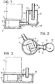
- 1 indicates the electrical engine driving the pump, 2 the mounting of said engine, closing at the top the cylindrical seat built in the body 4; 5 is the rotor of the pump in which the vanes 6 are lodged.
- Air is aspirated from duct 7 and expelled through outlet duct 8.
- the pressure difference between in and outlet air depends, as known, on the pump sizes, number of vanes, and position of inlet and outlet ports. It is also known that such a pump can be used either to compress or to depress air or any other gas.
- the container/separator 9 is inserted, consisting of cylindrical container 10 and cover 15.
- Cover 15 is provided with an inlet duct 11 and a vertical duct 12, wherein said duct 11 comes out.
- the vertical duct 12 comes up to cover 15 and provided at the top with the slot 13 wherefrom air comes out, arriving from the pump, approximately tangentially to the container wall.
- the same duct 12 is provided at the bottom with a small bore 14, wherefrom the oil collected in the container during the pump operation returns into the pump when this latter stops.
- the outlet duct 16 is disposed on the axis of the container and protrudes into its inside in such a way that the inlet air is compelled to move centerwards for entering into duct 16.
- duct 16 must be not long enough to arrive under the level of the oil collected at the bottom of the container when the pump is operating.
- the operation of the system is the following.
- a certain quantity of oil is collected inside the pump and, in some case, also in the container 10.
- Fig. 1 the oil level in the pump is indicated with line AA.
- bore 14 have a small diameter and a length of, at least, 2-3 millimiter, as indicated in Fig. 1.
- the container/separator 9 can, obviously, have different shapes, all the same operating in the same way.
- the same vertical section can be used as oil container/separator. In this case separation occurs only by gravity, when air slows down in the large vertical section.
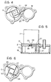
- FIGS 3, 4 show a possible embodiment of a pump/separator system which can be particularly advantageous from the standpoint of production costs.
- the cylindrical seat of pump 3 is constituted by a sintered ring 17, in a single piece with ring 18 of the container/separator.
- the upper plate 2, supporting the electric motor, and the lower plate 19 complete the assembly.
- the cylindrical seat of the pump and the container/separator are connected to each other through passage 20 formed in ring 17, the vertical channel 21 and passage 22 which opens into the container/separator in a substantially tangential direction.
- the oil returns from the separator into the pump through the little groove 23 formed in the bottom of ring 18.
- the pump In case the pump is used to create vacuum, a further power reduction can be obtained in the following way. Under these conditions the pump aspirates air from the users circuit until the absolute pressure p o in the latter reaches values of 0.2 ⁇ 0.4 bar. Obviously, the pump is designed in such a way that it can aspirate air at pressure p o , compress it up to atmospheric pressure and discharge it into atmosphere.
- the problem can be solved by adding a second outlet port, provided with a non-return valve - as shown in Fig. 5, 6 - which is opened before the normal outlet and prevents air from reaching too high pressures.
- FIGs. 5, 6 show the same pump of Figs. 3, 4 with this variation.
- Flange 2 supporting the electrical engine, is provided with the outlet bore 24 that, through duct 27, discharges air into vertical duct 21.
- the device operates as follows.
Landscapes
- Engineering & Computer Science (AREA)
- Mechanical Engineering (AREA)
- General Engineering & Computer Science (AREA)
- Rotary Pumps (AREA)
Claims (8)
- Periodisch arbeitende, pneumatische Flügelzellenpumpe der Art, die umfaßt:
einen mit Schlitzen versehenen Rotor, in denen die Flügel angeordnet sind;
einen zylindrischen Sitz, in dem der Rotor sich dreht,
wobei an ihrer Auslaßleitung ein Vorratsbehälter (9) einer geeigneten Form und Größe eingesetzt ist,
dadurch gekennzeichnet, daß alles so angeordnet ist, daß, wenn die Pumpe stationär ist, eine bestimmte Menge Öl innerhalb der Pumpe enthalten ist, wohingegen, wenn die Pumpe sich dreht, das Öl aus der Pumpe herausgedrängt und von dem Vorratsbehälter aufgefangen wird, wobei das Öl wieder in die Pumpe eintritt, wenn letztere anhält. - Periodisch arbeitende, pneumatische Flügelzellenpumpe nach Anspruch 1, dadurch gekennzeichnet, daß der Vorratsbehälter zum Trennen und Sammeln des Öls aus einem im wesentlichen vertikalen Abschnitt des Ausloßrohrs besteht.
- Periodisch arbeitende, pneumatische Flügelzellenpumpe nach Anspruch 1, dadurch gekennzeichnet, daß der Vorratsbehälter zum Sammeln des Öls, wenn sich die Pumpe dreht, aus einem Behälter (9) besteht, durch den die Luft, die aus der Pumpe kommt, strömt, wobei der Behälter so angeordnet ist, daß bei stationärer Pumpe das darin enthaltene Öl durch Schwerkraft in die Pumpe zurückkehrt.
- Periodisch arbeitende, pneumatische Flügelzellenpumpe nach Anspruch 1, dadurch gekennzeichnet, daß der Vorratsbehälter zum Sammeln des Öls aus einem Behälter/Abscheider (9) einer im wesentlichen zylindrischen Form besteht, in den Luft in einer tangentialen Richtung eintritt, um die Trennung des Öls von der Luft durch den Zentrifugaleffekt zu ermöglichen, wobei der Auslaß (16) aus dem Behälter in einer im wesentlichen zentralen Position parallel zur Zylinderachse angeordnet ist und eine Vorrichtung vorgesehen ist, um den Ausgang des Öls aus dem Behälter während des Pumpenbetriebs zu blockieren und dem Öl den Wiedereintritt in die Pumpe zu ermöglichen, wenn letztere anhält.
- Periodisch arbeitende, pneumatische Flügelzellenpumpe nach Anspruch 4, dadurch gekennzeichnet, daß der Behälter/Abscheider (9) aus zwei Plastikteilen besteht, wovon eines a) aus einem im wesentlichen zylindrischen Plastikbehälter (10) mit einem Einlaßrohr (11), das in eine vertikale Führung (12) mündet, besteht, wobei die vertikale Führung an ihrem oberen Bereich mit einer Auslaßöffnung (13) versehen ist, die die Luft tangential zur Behälterwand leitet, und an ihrem unteren Bereich mit einer engen Bohrung (14) versehen ist, durch die das von dem Behälter gesammelte Öl zur Pumpe zurückkehrt, wenn diese anhält, und wovon das andere b) aus einer Abdeckung (15) ebenfalls aus Plastik besteht, die mit einem Auslaßrohr (16) versehen ist, daß in den Behälter (10) über eine Länge hineinragt, die ausreichen muß, um das Austreten des zentrifugierten Öls zu verhindern, aber nicht unter den Pegel des in dem Behälter gesammelten Öls reichen darf, wobei die beiden Teile -der Behälter (10) und die Abdeckung (15)- durch jedes bekannte Verfahren miteinander verbunden sein können, zum Beispiel durch Ultraschallschweißen.
- Periodisch arbeitende, pneumatische Flügelzellenpumpe nach Anspruch 5, dadurch gekennzeichnet, daß die Bohrung (14) für die Ölrückführung am Boden der vertikalen Führung (12) unter dem Druck der von der Pumpe kommenden Luft steht und in einer Wand ausgeführt ist, die dicker als die derselben vertikalen Führung (12) ist, um den Rückfluß des Öls in die Pumpe zu verhindern, wenn diese arbeitet.
- Periodisch arbeitende, pneumatische Flügelzellenpumpe nach den Ansprüchen 1 und 4, dadurch gekennzeichnet, daß der zylindrische Sitz (3) und der Behälter/Abscheider (9) aus einem einzigen Stück, vorzugsweise aus gesintertem Material, bestehen, wobei das einzige Stück im wesentlichen aus einem ersten Ring (17), in dem der zylindrische Sitz angeordnet ist, und aus einem zweiten Ring (18) besteht, der den Behälter/Abscheider bildet, wobei die Ringe an ihren Enden von einem Flansch (2), der eine elektrische Antriebsmaschine (1) trägt, und einem zweiten Bodenflansch (19) verschlossen werden und miteinander über eine vertikale Führung (21) verbunden sind, die a) in ihrem untern Bereich mit dem zylindrischen Sitz über eine in der Wand desselben zylindrischen Sitzes ausgeführte Vertiefung (20) in Verbindung steht und b) in ihrem oberen Bereich mit dem Behälter/Abscheider über eine im wesentliche tangentiale Führung (22) in Verbindung steht, die in der Wand des Behälterrings (18) gearbeitet ist, wobei ein weiterer schmaler Durchlaß (23) am Boden zwischen Behälter und vertikaler Führung (21) durch eine kleine Einkerbung (23) in der Wand ausgeführt ist, durch die das Öl, das während des Pumpenbetriebs in dem Behälter gesammelt wurde, in die Pumpe zurückkehrt, wenn diese anhält.
- Periodisch arbeitende, pneumatische Flügelzellenpumpe nach Anspruch 1, dadurch gekennzeichnet, daß sie mit einer zweiten Auslaßöffnung (24) versehen ist, die mit einem Rückschlagventil (25, 26, 28) verbunden ist, wobei die zweite Öffnung vor der normalen Auslaßöffnung geöffnet wird und die Funktion hat, zu verhindern, daß Luft auf einen unnötig hohen Druck komprimiert wird, wenn der Druck in dem Benutzerkreislauf nahe dem Atmosphärendruck ist, wodurch die für die Pumpe erforderliche Leistung reduziert wird.
Applications Claiming Priority (2)
| Application Number | Priority Date | Filing Date | Title |
|---|---|---|---|
| IT67697/85A IT1182547B (it) | 1985-07-26 | 1985-07-26 | Pompa pneumatica a palette a funzionamento e con lubrificazione intermittente |
| IT6769785 | 1985-07-26 |
Publications (3)
| Publication Number | Publication Date |
|---|---|
| EP0210145A2 EP0210145A2 (de) | 1987-01-28 |
| EP0210145A3 EP0210145A3 (en) | 1989-01-04 |
| EP0210145B1 true EP0210145B1 (de) | 1992-01-02 |
Family
ID=11304587
Family Applications (1)
| Application Number | Title | Priority Date | Filing Date |
|---|---|---|---|
| EP86830213A Expired - Lifetime EP0210145B1 (de) | 1985-07-26 | 1986-07-17 | Periodisch arbeitende pneumatische Flügelzellenpumpe |
Country Status (3)
| Country | Link |
|---|---|
| EP (1) | EP0210145B1 (de) |
| DE (1) | DE3683206D1 (de) |
| IT (1) | IT1182547B (de) |
Families Citing this family (2)
| Publication number | Priority date | Publication date | Assignee | Title |
|---|---|---|---|---|
| US9103246B2 (en) | 2010-11-02 | 2015-08-11 | Ford Global Technologies, Llc | System and method for reducing vacuum degradation in a vehicle |
| JP6026380B2 (ja) * | 2013-09-30 | 2016-11-16 | 株式会社クボタ | ディーゼルエンジン |
Citations (1)
| Publication number | Priority date | Publication date | Assignee | Title |
|---|---|---|---|---|
| DE3322069A1 (de) * | 1983-06-18 | 1984-12-20 | Armatec FTS-Armaturen GmbH & Co KG, 7988 Wangen | Druckgasmaschine, insbesondere kompressor, mit umlaufschmierung |
Family Cites Families (4)
| Publication number | Priority date | Publication date | Assignee | Title |
|---|---|---|---|---|
| US1854318A (en) * | 1926-06-17 | 1932-04-19 | Westinghouse Electric & Mfg Co | Compressor |
| US3040973A (en) * | 1958-12-02 | 1962-06-26 | Prec Scient Company | Vacuum pump |
| DE1403568B2 (de) * | 1961-06-09 | 1974-08-15 | Leybold-Heraeus Gmbh & Co Kg, 5000 Koeln | Ölabscheider an einer Rotations-Vakuumpumpe |
| DE3322869A1 (de) * | 1983-06-24 | 1985-01-03 | Gebr. Philipp GmbH, 8750 Aschaffenburg | Huelsenanker |
-
1985
- 1985-07-26 IT IT67697/85A patent/IT1182547B/it active
-
1986
- 1986-07-17 EP EP86830213A patent/EP0210145B1/de not_active Expired - Lifetime
- 1986-07-17 DE DE8686830213T patent/DE3683206D1/de not_active Revoked
Patent Citations (1)
| Publication number | Priority date | Publication date | Assignee | Title |
|---|---|---|---|---|
| DE3322069A1 (de) * | 1983-06-18 | 1984-12-20 | Armatec FTS-Armaturen GmbH & Co KG, 7988 Wangen | Druckgasmaschine, insbesondere kompressor, mit umlaufschmierung |
Also Published As
| Publication number | Publication date |
|---|---|
| IT8567697A0 (it) | 1985-07-26 |
| EP0210145A2 (de) | 1987-01-28 |
| EP0210145A3 (en) | 1989-01-04 |
| DE3683206D1 (de) | 1992-02-13 |
| IT1182547B (it) | 1987-10-05 |
Similar Documents
| Publication | Publication Date | Title |
|---|---|---|
| US20200003199A1 (en) | Compressor | |
| CN113404693A (zh) | 油分离装置及压缩机 | |
| EP3486488B1 (de) | Kompressionsvorrichtung und trennverfahren für kontrollmassendurchfluss | |
| US5174740A (en) | Hermetic type scroll compressor with regulation of lubricant to the inlet | |
| EP0210145B1 (de) | Periodisch arbeitende pneumatische Flügelzellenpumpe | |
| CN101002022B (zh) | 单叶片真空泵 | |
| US5853443A (en) | Moisture separator for fluid compressor | |
| KR102510419B1 (ko) | 공기압축기용 멀티사이클론 기액 분리 장치 | |
| US5697771A (en) | Vacuum pump with oil separator | |
| WO1989012168A1 (en) | Liquid ring compressor | |
| JP4248201B2 (ja) | 気体圧縮機 | |
| CN209781208U (zh) | 一种旋片真空泵双级油气分离器 | |
| JP3073387B2 (ja) | 圧縮機用油回収装置 | |
| CN203051123U (zh) | 一种双螺杆二级增压空气压缩机 | |
| US4295806A (en) | Rotary compressor with wire gauze lubricant separator | |
| KR960038127A (ko) | 회전베인형 유체압기기 | |
| CN215486571U (zh) | 一种涡旋压缩机和空调器 | |
| KR100550490B1 (ko) | 라인내 오일 분리기 | |
| US3265009A (en) | Sewage pumping system | |
| CN223351247U (zh) | 一种油气分离装置及空气压缩系统 | |
| JPS6237978Y2 (de) | ||
| CN2688932Y (zh) | 旋转式防回油真空/压气两用泵 | |
| KR890006978A (ko) | 유냉식 유체 압축장치 | |
| KR100304573B1 (ko) | 밀폐형회전식압축기의유토출방지구조 | |
| US6394772B1 (en) | Oil transfer pump |
Legal Events
| Date | Code | Title | Description |
|---|---|---|---|
| PUAI | Public reference made under article 153(3) epc to a published international application that has entered the european phase |
Free format text: ORIGINAL CODE: 0009012 |
|
| AK | Designated contracting states |
Kind code of ref document: A2 Designated state(s): DE FR GB SE |
|
| PUAL | Search report despatched |
Free format text: ORIGINAL CODE: 0009013 |
|
| AK | Designated contracting states |
Kind code of ref document: A3 Designated state(s): DE FR GB SE |
|
| 17P | Request for examination filed |
Effective date: 19890710 |
|
| R17P | Request for examination filed (corrected) |
Effective date: 19890630 |
|
| 17Q | First examination report despatched |
Effective date: 19900418 |
|
| GRAA | (expected) grant |
Free format text: ORIGINAL CODE: 0009210 |
|
| AK | Designated contracting states |
Kind code of ref document: B1 Designated state(s): DE FR GB SE |
|
| REF | Corresponds to: |
Ref document number: 3683206 Country of ref document: DE Date of ref document: 19920213 |
|
| ET | Fr: translation filed | ||
| PGFP | Annual fee paid to national office [announced via postgrant information from national office to epo] |
Ref country code: GB Payment date: 19920617 Year of fee payment: 7 Ref country code: DE Payment date: 19920617 Year of fee payment: 7 |
|
| PGFP | Annual fee paid to national office [announced via postgrant information from national office to epo] |
Ref country code: SE Payment date: 19920624 Year of fee payment: 7 |
|
| PGFP | Annual fee paid to national office [announced via postgrant information from national office to epo] |
Ref country code: FR Payment date: 19920731 Year of fee payment: 7 |
|
| PLBI | Opposition filed |
Free format text: ORIGINAL CODE: 0009260 |
|
| 26 | Opposition filed |
Opponent name: LEYBOLD AKTIENGESELLSCHAFT Effective date: 19920930 |
|
| RDAG | Patent revoked |
Free format text: ORIGINAL CODE: 0009271 |
|
| STAA | Information on the status of an ep patent application or granted ep patent |
Free format text: STATUS: PATENT REVOKED |
|
| 27W | Patent revoked |
Effective date: 19930407 |
|
| GBPR | Gb: patent revoked under art. 102 of the ep convention designating the uk as contracting state |
Free format text: 930407 |
|
| EUG | Se: european patent has lapsed |
Ref document number: 86830213.4 Effective date: 19930825 |