EP0210095B1 - Dispositif de découpe de feuilles de matière plastique - Google Patents
Dispositif de découpe de feuilles de matière plastique Download PDFInfo
- Publication number
- EP0210095B1 EP0210095B1 EP86401375A EP86401375A EP0210095B1 EP 0210095 B1 EP0210095 B1 EP 0210095B1 EP 86401375 A EP86401375 A EP 86401375A EP 86401375 A EP86401375 A EP 86401375A EP 0210095 B1 EP0210095 B1 EP 0210095B1
- Authority
- EP
- European Patent Office
- Prior art keywords
- cutting
- blade
- cutting device
- axis
- rotation
- Prior art date
- Legal status (The legal status is an assumption and is not a legal conclusion. Google has not performed a legal analysis and makes no representation as to the accuracy of the status listed.)
- Expired
Links
- 239000002985 plastic film Substances 0.000 title description 2
- 229920003023 plastic Polymers 0.000 claims description 4
- 239000004033 plastic Substances 0.000 claims description 4
- 238000006073 displacement reaction Methods 0.000 claims description 3
- 239000000463 material Substances 0.000 claims description 3
- 230000001105 regulatory effect Effects 0.000 claims 2
- 239000011521 glass Substances 0.000 description 5
- 239000011229 interlayer Substances 0.000 description 4
- 238000009966 trimming Methods 0.000 description 4
- 238000004519 manufacturing process Methods 0.000 description 3
- 238000003490 calendering Methods 0.000 description 2
- 239000010410 layer Substances 0.000 description 2
- 230000007246 mechanism Effects 0.000 description 2
- 229920002037 poly(vinyl butyral) polymer Polymers 0.000 description 2
- 101100008044 Caenorhabditis elegans cut-1 gene Proteins 0.000 description 1
- 239000000470 constituent Substances 0.000 description 1
- 239000012530 fluid Substances 0.000 description 1
- 239000002184 metal Substances 0.000 description 1
- 238000012544 monitoring process Methods 0.000 description 1
- 229920002635 polyurethane Polymers 0.000 description 1
- 239000004814 polyurethane Substances 0.000 description 1
- 230000003313 weakening effect Effects 0.000 description 1
Images


Classifications
-
- B—PERFORMING OPERATIONS; TRANSPORTING
- B26—HAND CUTTING TOOLS; CUTTING; SEVERING
- B26D—CUTTING; DETAILS COMMON TO MACHINES FOR PERFORATING, PUNCHING, CUTTING-OUT, STAMPING-OUT OR SEVERING
- B26D3/00—Cutting work characterised by the nature of the cut made; Apparatus therefor
- B26D3/10—Making cuts of other than simple rectilinear form
-
- B—PERFORMING OPERATIONS; TRANSPORTING
- B32—LAYERED PRODUCTS
- B32B—LAYERED PRODUCTS, i.e. PRODUCTS BUILT-UP OF STRATA OF FLAT OR NON-FLAT, e.g. CELLULAR OR HONEYCOMB, FORM
- B32B17/00—Layered products essentially comprising sheet glass, or glass, slag, or like fibres
- B32B17/06—Layered products essentially comprising sheet glass, or glass, slag, or like fibres comprising glass as the main or only constituent of a layer, next to another layer of a specific material
- B32B17/10—Layered products essentially comprising sheet glass, or glass, slag, or like fibres comprising glass as the main or only constituent of a layer, next to another layer of a specific material of synthetic resin
- B32B17/10005—Layered products essentially comprising sheet glass, or glass, slag, or like fibres comprising glass as the main or only constituent of a layer, next to another layer of a specific material of synthetic resin laminated safety glass or glazing
- B32B17/10165—Functional features of the laminated safety glass or glazing
- B32B17/10293—Edge features, e.g. inserts or holes
-
- B—PERFORMING OPERATIONS; TRANSPORTING
- B23—MACHINE TOOLS; METAL-WORKING NOT OTHERWISE PROVIDED FOR
- B23D—PLANING; SLOTTING; SHEARING; BROACHING; SAWING; FILING; SCRAPING; LIKE OPERATIONS FOR WORKING METAL BY REMOVING MATERIAL, NOT OTHERWISE PROVIDED FOR
- B23D53/00—Machines or devices for sawing with strap saw-blades which are effectively endless in use, e.g. for contour cutting
- B23D53/04—Machines or devices for sawing with strap saw-blades which are effectively endless in use, e.g. for contour cutting with the wheels carrying the strap mounted shiftably or swingingly, i.e. during sawing, other than merely for adjustment
-
- B—PERFORMING OPERATIONS; TRANSPORTING
- B23—MACHINE TOOLS; METAL-WORKING NOT OTHERWISE PROVIDED FOR
- B23D—PLANING; SLOTTING; SHEARING; BROACHING; SAWING; FILING; SCRAPING; LIKE OPERATIONS FOR WORKING METAL BY REMOVING MATERIAL, NOT OTHERWISE PROVIDED FOR
- B23D55/00—Sawing machines or sawing devices working with strap saw blades, characterised only by constructional features of particular parts
- B23D55/02—Sawing machines or sawing devices working with strap saw blades, characterised only by constructional features of particular parts of frames; of tables
-
- B—PERFORMING OPERATIONS; TRANSPORTING
- B23—MACHINE TOOLS; METAL-WORKING NOT OTHERWISE PROVIDED FOR
- B23D—PLANING; SLOTTING; SHEARING; BROACHING; SAWING; FILING; SCRAPING; LIKE OPERATIONS FOR WORKING METAL BY REMOVING MATERIAL, NOT OTHERWISE PROVIDED FOR
- B23D59/00—Accessories specially designed for sawing machines or sawing devices
- B23D59/008—Accessories specially designed for sawing machines or sawing devices comprising computers
-
- B—PERFORMING OPERATIONS; TRANSPORTING
- B26—HAND CUTTING TOOLS; CUTTING; SEVERING
- B26D—CUTTING; DETAILS COMMON TO MACHINES FOR PERFORATING, PUNCHING, CUTTING-OUT, STAMPING-OUT OR SEVERING
- B26D1/00—Cutting through work characterised by the nature or movement of the cutting member or particular materials not otherwise provided for; Apparatus or machines therefor; Cutting members therefor
- B26D1/01—Cutting through work characterised by the nature or movement of the cutting member or particular materials not otherwise provided for; Apparatus or machines therefor; Cutting members therefor involving a cutting member which does not travel with the work
- B26D1/46—Cutting through work characterised by the nature or movement of the cutting member or particular materials not otherwise provided for; Apparatus or machines therefor; Cutting members therefor involving a cutting member which does not travel with the work having an endless band-knife or the like
- B26D1/465—Cutting through work characterised by the nature or movement of the cutting member or particular materials not otherwise provided for; Apparatus or machines therefor; Cutting members therefor involving a cutting member which does not travel with the work having an endless band-knife or the like for thin material, e.g. for sheets, strips or the like
-
- B—PERFORMING OPERATIONS; TRANSPORTING
- B26—HAND CUTTING TOOLS; CUTTING; SEVERING
- B26D—CUTTING; DETAILS COMMON TO MACHINES FOR PERFORATING, PUNCHING, CUTTING-OUT, STAMPING-OUT OR SEVERING
- B26D1/00—Cutting through work characterised by the nature or movement of the cutting member or particular materials not otherwise provided for; Apparatus or machines therefor; Cutting members therefor
- B26D1/01—Cutting through work characterised by the nature or movement of the cutting member or particular materials not otherwise provided for; Apparatus or machines therefor; Cutting members therefor involving a cutting member which does not travel with the work
- B26D1/46—Cutting through work characterised by the nature or movement of the cutting member or particular materials not otherwise provided for; Apparatus or machines therefor; Cutting members therefor involving a cutting member which does not travel with the work having an endless band-knife or the like
- B26D1/48—Cutting through work characterised by the nature or movement of the cutting member or particular materials not otherwise provided for; Apparatus or machines therefor; Cutting members therefor involving a cutting member which does not travel with the work having an endless band-knife or the like with tensioning means
- B26D1/485—Cutting through work characterised by the nature or movement of the cutting member or particular materials not otherwise provided for; Apparatus or machines therefor; Cutting members therefor involving a cutting member which does not travel with the work having an endless band-knife or the like with tensioning means for thin material, e.g. for sheets, strips or the like
-
- B—PERFORMING OPERATIONS; TRANSPORTING
- B32—LAYERED PRODUCTS
- B32B—LAYERED PRODUCTS, i.e. PRODUCTS BUILT-UP OF STRATA OF FLAT OR NON-FLAT, e.g. CELLULAR OR HONEYCOMB, FORM
- B32B17/00—Layered products essentially comprising sheet glass, or glass, slag, or like fibres
- B32B17/06—Layered products essentially comprising sheet glass, or glass, slag, or like fibres comprising glass as the main or only constituent of a layer, next to another layer of a specific material
- B32B17/10—Layered products essentially comprising sheet glass, or glass, slag, or like fibres comprising glass as the main or only constituent of a layer, next to another layer of a specific material of synthetic resin
- B32B17/10005—Layered products essentially comprising sheet glass, or glass, slag, or like fibres comprising glass as the main or only constituent of a layer, next to another layer of a specific material of synthetic resin laminated safety glass or glazing
- B32B17/1055—Layered products essentially comprising sheet glass, or glass, slag, or like fibres comprising glass as the main or only constituent of a layer, next to another layer of a specific material of synthetic resin laminated safety glass or glazing characterized by the resin layer, i.e. interlayer
- B32B17/10761—Layered products essentially comprising sheet glass, or glass, slag, or like fibres comprising glass as the main or only constituent of a layer, next to another layer of a specific material of synthetic resin laminated safety glass or glazing characterized by the resin layer, i.e. interlayer containing vinyl acetal
-
- B—PERFORMING OPERATIONS; TRANSPORTING
- B32—LAYERED PRODUCTS
- B32B—LAYERED PRODUCTS, i.e. PRODUCTS BUILT-UP OF STRATA OF FLAT OR NON-FLAT, e.g. CELLULAR OR HONEYCOMB, FORM
- B32B17/00—Layered products essentially comprising sheet glass, or glass, slag, or like fibres
- B32B17/06—Layered products essentially comprising sheet glass, or glass, slag, or like fibres comprising glass as the main or only constituent of a layer, next to another layer of a specific material
- B32B17/10—Layered products essentially comprising sheet glass, or glass, slag, or like fibres comprising glass as the main or only constituent of a layer, next to another layer of a specific material of synthetic resin
- B32B17/10005—Layered products essentially comprising sheet glass, or glass, slag, or like fibres comprising glass as the main or only constituent of a layer, next to another layer of a specific material of synthetic resin laminated safety glass or glazing
- B32B17/10807—Making laminated safety glass or glazing; Apparatus therefor
- B32B17/1099—After-treatment of the layered product, e.g. cooling
-
- Y—GENERAL TAGGING OF NEW TECHNOLOGICAL DEVELOPMENTS; GENERAL TAGGING OF CROSS-SECTIONAL TECHNOLOGIES SPANNING OVER SEVERAL SECTIONS OF THE IPC; TECHNICAL SUBJECTS COVERED BY FORMER USPC CROSS-REFERENCE ART COLLECTIONS [XRACs] AND DIGESTS
- Y10—TECHNICAL SUBJECTS COVERED BY FORMER USPC
- Y10T—TECHNICAL SUBJECTS COVERED BY FORMER US CLASSIFICATION
- Y10T83/00—Cutting
- Y10T83/162—With control means responsive to replaceable or selectable information program
- Y10T83/173—Arithmetically determined program
-
- Y—GENERAL TAGGING OF NEW TECHNOLOGICAL DEVELOPMENTS; GENERAL TAGGING OF CROSS-SECTIONAL TECHNOLOGIES SPANNING OVER SEVERAL SECTIONS OF THE IPC; TECHNICAL SUBJECTS COVERED BY FORMER USPC CROSS-REFERENCE ART COLLECTIONS [XRACs] AND DIGESTS
- Y10—TECHNICAL SUBJECTS COVERED BY FORMER USPC
- Y10T—TECHNICAL SUBJECTS COVERED BY FORMER US CLASSIFICATION
- Y10T83/00—Cutting
- Y10T83/303—With tool sharpener or smoother
-
- Y—GENERAL TAGGING OF NEW TECHNOLOGICAL DEVELOPMENTS; GENERAL TAGGING OF CROSS-SECTIONAL TECHNOLOGIES SPANNING OVER SEVERAL SECTIONS OF THE IPC; TECHNICAL SUBJECTS COVERED BY FORMER USPC CROSS-REFERENCE ART COLLECTIONS [XRACs] AND DIGESTS
- Y10—TECHNICAL SUBJECTS COVERED BY FORMER USPC
- Y10T—TECHNICAL SUBJECTS COVERED BY FORMER US CLASSIFICATION
- Y10T83/00—Cutting
- Y10T83/707—By endless band or chain knife
- Y10T83/7076—With programming means
-
- Y—GENERAL TAGGING OF NEW TECHNOLOGICAL DEVELOPMENTS; GENERAL TAGGING OF CROSS-SECTIONAL TECHNOLOGIES SPANNING OVER SEVERAL SECTIONS OF THE IPC; TECHNICAL SUBJECTS COVERED BY FORMER USPC CROSS-REFERENCE ART COLLECTIONS [XRACs] AND DIGESTS
- Y10—TECHNICAL SUBJECTS COVERED BY FORMER USPC
- Y10T—TECHNICAL SUBJECTS COVERED BY FORMER US CLASSIFICATION
- Y10T83/00—Cutting
- Y10T83/707—By endless band or chain knife
- Y10T83/7226—With means to guard the tension
- Y10T83/7239—With means to vary distance between pulley or sprocket axes
- Y10T83/7251—Including means to yieldably bias pulley
- Y10T83/7258—By fluid means
Definitions
- the present invention relates to the cutting of sheets or films formed from one or more layers of plastic material, in particular to the cutting of transparent or translucent sheets, capable of being used in the manufacture of laminated glazing. More particularly, the invention relates to a device for cutting these sheets, temporarily or permanently assembled with the other elements of the glazing, by trimming.
- laminated glazing in particular safety glazing formed from two sheets of glass and an interlayer sheet or layer of plastic material, for example polyvinyl butyral or polyurethane
- the constituent elements of the glazing are assembled by stacking the elements followed by calendering by passing the stack between pressure rollers, and an autoclave cycle.
- the interlayer plastic sheet is in the form of a generally _ trapezoidal primitive whose format is slightly larger than that of the glazing.
- the parts of the interlayer sheet which project beyond the glazing are cut manually by trimming with a metal blade, the worker who performs this cutting keeping the blade pressed against the edge of the glazing. It is a long and costly labor operation. In addition, it is sometimes not very precise and it is then necessary to deburr, generally after the autoclave cycle, the parts of the interlayer which still extend beyond the glazing. Another drawback of this manual cutting is that the tool risks attacking the edges of the glass sheets in places and thus weakening the glazing. Finally, the blades used wear very quickly, and it is essential to change them often.
- Document GB-A-2 144 363 also discloses a cutting head for trimming laminated glazing, provided with a cutting edge ribbon in the shape of a band saw blade, the cutting head being mounted at the end of an arm connected to drive means.
- the invention provides an improved cutting device, fully automatic, perfectly reliable, which can easily be integrated into the production lines of laminated glazing.
- the device according to the invention comprises a cutting head provided with a cutting edge ribbon in the form of a band saw blade, characterized in that the cutting head is mounted on a horizontal axis of rotation, itself mounted at end of a vertical column mounted rotating around a vertical axis z, on a main column which can move along the three orthogonal Cartesian axes x, y, z, while being slidably mounted vertically along the axis -z on a structure capable of move along the two axes x and y, and in that the entire device is commanded and controlled by electronic and digital means.
- the cutting head according to the invention can therefore move along three orthogonal Cartesian axes, and further along two orthogonal axes of rotation.
- means are provided which automatically and periodically control the change of the cutting blade.
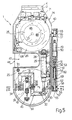
- the cutting head 1 has an upper plate 2, connected to an axis of rotation 3, allowing rotation of this plate 2 around the y axis (in Figures 1 and 2, we represents the orthogonal Cartesian ternary axes x, y and z, for the reference of the movements which will be described later).
- the plate 2 is connected to a U-shaped fork 4, mounted on an axis at the lower end of an internal column 5 of a main vertical column 6, arranged along the axis z.
- Column 5 can rotate around the z axis, relative to column 6, by means of command and position monitoring mechanisms of the type already mentioned.
- the column 6 can move vertically, relative to a horizontal beam 7, arranged along the y axis, thanks to a motor 8, secured to a structure 12 supported on the beam 7, which has an output pinion 9 meshing with a rack 10 fixed to the column 6.
- the structure 12 fixed to the beam 7, and housing the vertical slide column 6, also has a mechanism, not shown, for counterbalancing the weight of the column 6.
- the structure 12, as shown in FIG. 1, is also connected to a motor 13 for driving ment of the structure 12, along the y axis.
- such a motor 13 has an output pinion 14, which meshes with a rack 15 fixed below the beam 7.
- a motor 17 which controls the movement of the beam 7 d 'after the x axis, and which has an output pinion 18 which meshes with a rack 19 fixed towards the upper zone of a beam 20 placed along the x axis and supported at the ends of 2 vertical columns 21.
- Des carriages 22 rotate the horizontal beam 7 on the perpendicular beams 20.
- the cutting head 1 has a main part 24, with a part 40 in the form of a box open partially laterally, fixed to the upper plate 2.
- This part 40 on one of its internal walls 24 carries a motor 25, fixed above, which controls the rotation, via a pin 27, of a pulley 26 which comes out of this part 24.
- a motor 25 fixed above, which controls the rotation, via a pin 27, of a pulley 26 which comes out of this part 24.
- a motor 25 fixed above, which controls the rotation, via a pin 27, of a pulley 26 which comes out of this part 24.
- In the central zone of the part 40 is mounted on an axis, one end 28 of an actuating cylinder 29, which has a rod 30 having an end 31 mounted on an axis at one end 32 of a profiled tubular body 33, which, at the other end, is fixed on a pivot 34 carried by 2 end pads, is fixed on a pivot 34 carried by 2 end pads 35, by the beam 40 (fig. 6).
- a pin 41 to which is hooked one end of a tension spring 42, which, at the other end, is linked to a support 43 fixed to the part 40.
- a cutting blade 44 metallic, in the form of a ribbon, with sharp edges, which is tensioned by means of the operating cylinder control system 29, and this in a manner which will be described in more detail later.
- This cutting blade 44 is enclosed in the head 1, by a cover 45, which has an opening 47, U-shaped, which uncovers a portion of the cutting blade 44 with which the element to be cut comes into contact.
- a jack 49 which is housed, as shown in FIG. 5, in a cylindrical portion 50 fixed laterally to the part 40.
- a such a jack 49 has a movable rod 51 with a head 52 which, by linear displacement, can act on one end 53 of a pusher 54, having a lower part 55 provided with a helical groove 56, with which a pin 57 carried cooperates by a part 58 which, as shown in FIG. 6, is connected to a lateral end of the cover 45, in the lower zone.
- a pin 59 which is housed in a vertical groove 60 of the upper part of the pusher 54, to prevent the rotation of the latter around its axis.
- a cylindrical spring 61 supported by its lower end on a ring 62, fixed between the part 50 and arranged coaxially with the pusher 54, while the upper part of the spring 61 s' presses against a washer 63 fixed to the end 53 of the pusher 54.
- a part 65 is fixed, coaxial with the lower part 58, and disposed on a pivot 66 which is guided by a part 67 laterally fixed to the part 40.
- a magnetic plate 68 Above the opening 47, in the part 40, is fixed a magnetic plate 68, ensuring the closing of the cover 45.
- On the part 40 is also a proximity detector 70 which detects the position for closing and opening this cover 45.
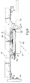
- an equipment 73 is illustrated for the automatic change of the cutting blade 44, which comprises two parallel crosspieces 74, carrying a plate 75, on which are fixed semi-circular bars of dimensions slightly larger than those that the cutting blade 44 is made to take when it is between the two pulleys 26 and 39, in the cutting head 1.
- On these bars 76 are arranged magnets 77 on which there is a spare cutting blade 44 .
- a proximity detector 78 is arranged in the upper part of the plate 75 in correspondence with the zone in which the shaft 27 of the pulley 26 of the cutting head 1 is present, for the change of the cutting blade which will be described later and as shown by hatched lines in FIGS. 7 and 8, a proximity detector 78 is arranged.
- Another proximity detector 79 serving to detect the presence of a spare blade 44, is fixed to the lower cross member 74.
- the two cross members 74 are fixed, at their respective ends, to brackets 81 with a possibility of adjustment for the longitudinal position; these brackets are in turn fixed to the support columns 82 partially shown, themselves fixed to the columns 21, in an area accessible to the cutting head 1.
- Sharpening equipment 83 for the cutting blade 44 is shown in FIG. 1. It comprises a sharpening wheel and is supported by a support 84 which is placed in an area between the columns 21, accessible to the head of cutting 1. Between the columns 21, parallel to the direction of the horizontal cross member 7 is placed a transport device 85 for the glazing 86, which must be cut.
- this transport equipment 85 may comprise transporting carriages with several rows of pins 87 parallel to the transport line which support these glazings 86 consisting of two sheets of glass 89, between which is placed a sheet 88 of larger dimension, made of plastic, in particular polyvinyl butyral, which, in this way, overflows from the sheets of glass 89 and which must be cut using the head of cut 1 object of the present invention, by a clipping of the glazing.
- FIG 2 are indicated, in hatched lines, the rows of pins 87 of the transport equipment 85 for the glazing 86. Between the columns 21 is provided an equipment 91 for removing the glazing 86 from the transport equipment 85 This equipment 91 has a base frame 92 and a central part 93 which can be lifted by means of an operating jack 94 and which has an upper plane 95 with suction cups 96 bearing under the glazing 86.
- the various movements of movement or rotation for the cutting head 1 are dictated by a microprocessor 98 which controls and controls the operations linked to the operation of the device.
- the glazing 86 provided with the sheet 88 to be cut by trimming is transported from the transport equipment 85 to the equipment 91 which, controlled by the control center 98, places it in the raised position relative to the transport equipment 85 as illustrated in FIG. 2 for cutting.
- the center 98 controls the movement of the cutting head 1 with a movement control on 5 axes (3 of displacement and 2 of rotation), so as to follow the edge of the glazing 86 with the zone of the blade.
- cutting 44 which passes through the opening 47.
- This cutting blade 44 is driven by the pulley 26 which is actuated by the motor 25.
- the blade is kept in tension between the pulley 26 and the pulley 39 by the action of the spring 42 which rotates, in a clockwise direction, the profiled tubular body 33 which supports the pivot 34.
- the equipment 91 by means of the lowering of the jack 94 replaces the glazing 86 on the conveyor 85 which sends it to the phases following work.
- the path of the cutting head 1 with the cutting blade 44 around the edge of the glazing 86 to be cut can be controlled by the control center 98 after it has made a first course to establish its program.
- control center 98 can automatically control the approach of the cutting head 1 and therefore of the cutting blade 44 to the equipment 83 for sharpening the cutting edge of the cutting blade 44.
- the cutting head 1 After a prefixed number of cutting cycles, the cutting head 1 automatically comes to the equipment 73 to perform, automatically, the operation of changing the blade 44.
- the cover 45 of the part 40 opens by means of the jack 54 which, thanks to the helical groove 56 of the lower part 55 determines the rotation of the pin 57 inserted in this groove 56 and therefore the rotation of the part 58 to which the pin 57 is attached; the part 58 connected to the cover 45 therefore turns the cover 45 which is placed in the hatched and open configuration, which is illustrated in FIG. 8.
- the worn cutting blade 44 can be removed by the operation of the jack 29 which, by removing the rod 30 exerts an anterior rotation on the profiled tubular body 33 around the pivot 34 and in opposition to the elastic force of the spring 42 for thus bringing the axis 38 of the pulley 39 closer to the axis of the upper pulley 26 thus making the cutting blade 44 free.
- the cutting head 1 via the control center is facing the equipment 73 as illustrated in FIG. 8. This position is signaled by the detector 78.
- the new cutting blade 44 placed in the equipment 73 by means of the magnets 77 is therefore taken up by the cutting head 1 thanks to the switching on in the opposite direction, from the jack 29 which, moving the axis of the pulley 39 away from the axis of the upper pulley 26, exerts a tension on this cutting blade 44 detaching it from the magnets 77.
- the control center 98 controls the distance from the open cutting head 1 of the equipment t 73 and the closing of the cover 45 on the internal wall 23 of the part 40 thanks to the operating jack 49 which operates in the opposite direction to that described. In this way, the pusher 54 is offset upwards thanks to the operation of the spring 61.
Landscapes
- Engineering & Computer Science (AREA)
- Mechanical Engineering (AREA)
- Life Sciences & Earth Sciences (AREA)
- Forests & Forestry (AREA)
- Re-Forming, After-Treatment, Cutting And Transporting Of Glass Products (AREA)
- Control Of Cutting Processes (AREA)
- Sawing (AREA)
- Processing Of Stones Or Stones Resemblance Materials (AREA)
Applications Claiming Priority (2)
| Application Number | Priority Date | Filing Date | Title |
|---|---|---|---|
| FR8509627A FR2583673B1 (fr) | 1985-06-25 | 1985-06-25 | Dispositif de decoupe de feuilles de matiere plastique |
| FR8509627 | 1985-06-25 |
Publications (2)
| Publication Number | Publication Date |
|---|---|
| EP0210095A1 EP0210095A1 (fr) | 1987-01-28 |
| EP0210095B1 true EP0210095B1 (fr) | 1989-08-30 |
Family
ID=9320635
Family Applications (1)
| Application Number | Title | Priority Date | Filing Date |
|---|---|---|---|
| EP86401375A Expired EP0210095B1 (fr) | 1985-06-25 | 1986-06-23 | Dispositif de découpe de feuilles de matière plastique |
Country Status (8)
| Country | Link |
|---|---|
| US (1) | US4713994A (fi) |
| EP (1) | EP0210095B1 (fi) |
| JP (1) | JPH0741578B2 (fi) |
| KR (1) | KR950000209B1 (fi) |
| BR (1) | BR8602882A (fi) |
| DE (1) | DE3665278D1 (fi) |
| FI (1) | FI87056C (fi) |
| FR (1) | FR2583673B1 (fi) |
Families Citing this family (13)
| Publication number | Priority date | Publication date | Assignee | Title |
|---|---|---|---|---|
| FR2607444B1 (fr) * | 1986-12-02 | 1989-02-10 | Saint Gobain Vitrage | Dispositif de decoupe de feuilles de matiere plastique |
| JPS63300889A (ja) * | 1987-05-29 | 1988-12-08 | 旭硝子株式会社 | 曲板の周縁処理用メカニカルハンド |
| DE4005143A1 (de) * | 1990-02-17 | 1991-08-22 | Keuro Maschinenbau Gmbh | Vertikalbandsaege |
| DE4008775A1 (de) * | 1990-03-19 | 1991-09-26 | Elastogran Polyurethane Gmbh | Vorrichtung zum abtrennen von sandwichelementen von einem kontinuierlich zugefuehrten profilstrang |
| GB9101762D0 (en) * | 1991-01-26 | 1991-03-13 | Pilkington Glass Ltd | Manufacture of laminated windows |
| US5407415A (en) * | 1993-01-21 | 1995-04-18 | The Boeing Company | Automated composite trim workstation |
| FR2757093B1 (fr) * | 1996-12-12 | 1999-01-08 | Saint Gobain Vitrage | Procede de rectification du chant d'un intercalaire assemblant deux substrats |
| JP4711236B2 (ja) * | 2006-09-22 | 2011-06-29 | 株式会社日立プラントテクノロジー | バンドソー型切断装置及びバンドソー型切断装置による切断方法 |
| IT1391183B1 (it) * | 2008-07-21 | 2011-11-18 | Bottero Spa | Dispositivo per la rifilatura di una lastra di vetro stratificata |
| CN103722238B (zh) * | 2013-11-22 | 2016-04-20 | 太仓威格玛机械设备有限公司 | 双头切割中心 |
| KR101661926B1 (ko) | 2014-07-04 | 2016-10-05 | 삼성중공업 주식회사 | 재단 장치 |
| JP6404138B2 (ja) * | 2015-02-12 | 2018-10-10 | 株式会社マキタ | 帯鋸切断機 |
| CN111267164B (zh) * | 2020-03-06 | 2024-06-14 | 佛山市顺德区宇顺新材料科技有限公司 | 全自动泡沫薄切装置 |
Family Cites Families (10)
| Publication number | Priority date | Publication date | Assignee | Title |
|---|---|---|---|---|
| DE1147374B (de) * | 1956-02-13 | 1963-04-18 | Magna Power Tool Corp | Bandsaege |
| FR1520023A (fr) * | 1966-10-03 | 1968-04-05 | Intercontinental Machinery Cor | Machine automatique à découper |
| US3548697A (en) * | 1969-05-05 | 1970-12-22 | Gerber Garment Technology Inc | Apparatus for cutting sheet material |
| AT317694B (de) * | 1970-12-17 | 1974-09-10 | Bode & Co Vorm Wegmann & Co | Verriegelungsvorrichtung für den mit Hilfe einer Drehsäule verschwenkbaren Türflügel einer Schwingtüre |
| US4111085A (en) * | 1977-05-10 | 1978-09-05 | Lockheed Corporation | Compound curvature cutting machine |
| US4393450A (en) * | 1980-08-11 | 1983-07-12 | Trustees Of Dartmouth College | Three-dimensional model-making system |
| FR2510029A1 (fr) * | 1981-07-24 | 1983-01-28 | Saint Gobain Vitrage | Dispositif de decoupe de feuilles de matiere plastique |
| US4491047A (en) * | 1982-05-28 | 1985-01-01 | Emerson Electric Co. | Direct drive band saw |
| DE3319623C2 (de) * | 1983-05-30 | 1985-09-05 | Schmid & Wezel, 7133 Maulbronn | Bandsäge zum Teilen von Tierkörpern |
| JPS6034298A (ja) * | 1983-08-02 | 1985-02-21 | セントラル硝子株式会社 | 板ガラス間に挾持された中間膜端部の切断装置 |
-
1985
- 1985-06-25 FR FR8509627A patent/FR2583673B1/fr not_active Expired
-
1986
- 1986-06-20 BR BR8602882A patent/BR8602882A/pt not_active IP Right Cessation
- 1986-06-23 DE DE8686401375T patent/DE3665278D1/de not_active Expired
- 1986-06-23 EP EP86401375A patent/EP0210095B1/fr not_active Expired
- 1986-06-24 JP JP61146285A patent/JPH0741578B2/ja not_active Expired - Fee Related
- 1986-06-24 FI FI862678A patent/FI87056C/fi not_active IP Right Cessation
- 1986-06-25 US US06/878,440 patent/US4713994A/en not_active Expired - Lifetime
- 1986-06-25 KR KR1019860005087A patent/KR950000209B1/ko not_active IP Right Cessation
Also Published As
| Publication number | Publication date |
|---|---|
| FI87056B (fi) | 1992-08-14 |
| FI862678A (fi) | 1986-12-26 |
| FR2583673B1 (fr) | 1989-03-10 |
| KR950000209B1 (ko) | 1995-01-12 |
| EP0210095A1 (fr) | 1987-01-28 |
| KR870000142A (ko) | 1987-02-16 |
| JPH0741578B2 (ja) | 1995-05-10 |
| FI87056C (fi) | 1992-11-25 |
| US4713994A (en) | 1987-12-22 |
| DE3665278D1 (en) | 1989-10-05 |
| BR8602882A (pt) | 1987-02-17 |
| FI862678A0 (fi) | 1986-06-24 |
| FR2583673A1 (fr) | 1986-12-26 |
| JPS61297009A (ja) | 1986-12-27 |
Similar Documents
| Publication | Publication Date | Title |
|---|---|---|
| EP0210095B1 (fr) | Dispositif de découpe de feuilles de matière plastique | |
| CA1263299A (fr) | Procede de fabrication de vitrages feuilletes et dispositif pour la mise en oeuvre du procede | |
| EP0270452B1 (fr) | Dispositif de découpe de feuilles de matière plastique | |
| EP0210923B1 (fr) | Procédé et dispositif pour la préhension, le transfert et la dépose d'une feuille de matière plastique souple | |
| FR2535355A1 (fr) | Procede et dispositif de chargement de feuilles et etiqueteuse pour machine a decouper automatique | |
| EP0115353B1 (fr) | Dispositif destiné à déplacer, devant des moyens d'usinage et dans le sens de sa longueur un profilé à usiner | |
| FR2631878A1 (fr) | Dispositif pour decouper un stratifie | |
| FR2652532A1 (fr) | Dispositif pour decouper un feuillete. | |
| EP0028988B1 (en) | Process and device for separating the edges from a glass sheet bearing a closed-contour cutting line | |
| FR2674787A1 (fr) | Machine de coupe et table de reception combinees. | |
| FR2532298A1 (fr) | Appareil et procede pour la decoupe des bords d'une feuille de verre | |
| FR2680360A1 (fr) | Dispositif de transfert lineraire a plateaux libres. | |
| EP0239430B1 (fr) | Procédé et dispositif pour l'assemblage automatique de vitrages feuilletés | |
| EP0087342A1 (fr) | Dispositif d'alignement pour l'accostage et le soudage bord à bord de tôles | |
| EP0274295B1 (fr) | Procédé et dispositif d'assemblage automatique de vitrages feuilletés | |
| FR2629448A1 (fr) | Appareillage pour decouper une piece en un materiau du type verre ou ceramique le long d'une ligne incisee | |
| EP0334277B1 (fr) | Machine à relier des liasses de feuilles par brochage | |
| FR2621010A1 (fr) | Machine pour operculer les barquettes de conditionnement de plats cuisines ou autres similaires | |
| FR2518928A1 (fr) | Dispositif de fabrication de sachets en matiere plastique | |
| EP0642461B1 (fr) | Dispositif de redressement d'une nappe de matiere, par exemple de carton, defilant en continu | |
| FR2693702A1 (fr) | Procédé de mise en place d'un tronçon de bande de thermoscellage au-dessus de récipients et dispositif de mise en Óoeuvre. | |
| EP0052057B1 (fr) | Procédé et machine pour recouvrir une charge d'une gaine tubulaire | |
| WO2001074511A1 (fr) | Centre de poinçonnage, destine notamment au poinçonnage de toles | |
| EP0963282B1 (fr) | Dispositif de coupe precise d'un materiau en feuille mince | |
| FR2625946A1 (fr) | Installation de fabrication et d'empilage de sacs, sachets, etc. en matiere thermoplastique |
Legal Events
| Date | Code | Title | Description |
|---|---|---|---|
| PUAI | Public reference made under article 153(3) epc to a published international application that has entered the european phase |
Free format text: ORIGINAL CODE: 0009012 |
|
| AK | Designated contracting states |
Kind code of ref document: A1 Designated state(s): BE DE FR GB IT SE |
|
| 17P | Request for examination filed |
Effective date: 19870718 |
|
| 17Q | First examination report despatched |
Effective date: 19880608 |
|
| GRAA | (expected) grant |
Free format text: ORIGINAL CODE: 0009210 |
|
| AK | Designated contracting states |
Kind code of ref document: B1 Designated state(s): BE DE FR GB IT SE |
|
| REF | Corresponds to: |
Ref document number: 3665278 Country of ref document: DE Date of ref document: 19891005 |
|
| ITF | It: translation for a ep patent filed | ||
| GBT | Gb: translation of ep patent filed (gb section 77(6)(a)/1977) | ||
| RAP4 | Party data changed (patent owner data changed or rights of a patent transferred) |
Owner name: SAINT GOBAIN VITRAGE INTERNATIONAL |
|
| PLBE | No opposition filed within time limit |
Free format text: ORIGINAL CODE: 0009261 |
|
| STAA | Information on the status of an ep patent application or granted ep patent |
Free format text: STATUS: NO OPPOSITION FILED WITHIN TIME LIMIT |
|
| 26N | No opposition filed | ||
| ITTA | It: last paid annual fee | ||
| EAL | Se: european patent in force in sweden |
Ref document number: 86401375.0 |
|
| REG | Reference to a national code |
Ref country code: GB Ref legal event code: IF02 |
|
| PGFP | Annual fee paid to national office [announced via postgrant information from national office to epo] |
Ref country code: SE Payment date: 20040604 Year of fee payment: 19 |
|
| PGFP | Annual fee paid to national office [announced via postgrant information from national office to epo] |
Ref country code: FR Payment date: 20040616 Year of fee payment: 19 |
|
| PGFP | Annual fee paid to national office [announced via postgrant information from national office to epo] |
Ref country code: BE Payment date: 20040617 Year of fee payment: 19 |
|
| PGFP | Annual fee paid to national office [announced via postgrant information from national office to epo] |
Ref country code: GB Payment date: 20040623 Year of fee payment: 19 |
|
| PGFP | Annual fee paid to national office [announced via postgrant information from national office to epo] |
Ref country code: DE Payment date: 20040701 Year of fee payment: 19 |
|
| PG25 | Lapsed in a contracting state [announced via postgrant information from national office to epo] |
Ref country code: IT Free format text: LAPSE BECAUSE OF NON-PAYMENT OF DUE FEES;WARNING: LAPSES OF ITALIAN PATENTS WITH EFFECTIVE DATE BEFORE 2007 MAY HAVE OCCURRED AT ANY TIME BEFORE 2007. THE CORRECT EFFECTIVE DATE MAY BE DIFFERENT FROM THE ONE RECORDED. Effective date: 20050623 Ref country code: GB Free format text: LAPSE BECAUSE OF NON-PAYMENT OF DUE FEES Effective date: 20050623 |
|
| PG25 | Lapsed in a contracting state [announced via postgrant information from national office to epo] |
Ref country code: SE Free format text: LAPSE BECAUSE OF NON-PAYMENT OF DUE FEES Effective date: 20050624 |
|
| PG25 | Lapsed in a contracting state [announced via postgrant information from national office to epo] |
Ref country code: BE Free format text: LAPSE BECAUSE OF NON-PAYMENT OF DUE FEES Effective date: 20050630 |
|
| PG25 | Lapsed in a contracting state [announced via postgrant information from national office to epo] |
Ref country code: DE Free format text: LAPSE BECAUSE OF NON-PAYMENT OF DUE FEES Effective date: 20060103 |
|
| EUG | Se: european patent has lapsed | ||
| PG25 | Lapsed in a contracting state [announced via postgrant information from national office to epo] |
Ref country code: FR Free format text: LAPSE BECAUSE OF NON-PAYMENT OF DUE FEES Effective date: 20060228 |
|
| GBPC | Gb: european patent ceased through non-payment of renewal fee |
Effective date: 20050623 |
|
| REG | Reference to a national code |
Ref country code: FR Ref legal event code: ST Effective date: 20060228 |
|
| BERE | Be: lapsed |
Owner name: *SAINT-GOBAIN VITRAGE Effective date: 20050630 |