EP0210010B1 - Transportierbares Konstruktionssystem - Google Patents
Transportierbares Konstruktionssystem Download PDFInfo
- Publication number
- EP0210010B1 EP0210010B1 EP86305209A EP86305209A EP0210010B1 EP 0210010 B1 EP0210010 B1 EP 0210010B1 EP 86305209 A EP86305209 A EP 86305209A EP 86305209 A EP86305209 A EP 86305209A EP 0210010 B1 EP0210010 B1 EP 0210010B1
- Authority
- EP
- European Patent Office
- Prior art keywords
- components
- lock
- assembly
- male
- pin member
- Prior art date
- Legal status (The legal status is an assumption and is not a legal conclusion. Google has not performed a legal analysis and makes no representation as to the accuracy of the status listed.)
- Expired - Lifetime
Links
- 238000010276 construction Methods 0.000 title claims description 104
- 230000000712 assembly Effects 0.000 claims description 159
- 238000000429 assembly Methods 0.000 claims description 159
- 230000015572 biosynthetic process Effects 0.000 claims description 17
- 238000005755 formation reaction Methods 0.000 claims description 17
- 230000033001 locomotion Effects 0.000 claims description 15
- 125000006850 spacer group Chemical group 0.000 claims description 10
- 238000000034 method Methods 0.000 claims description 5
- 238000012546 transfer Methods 0.000 claims description 4
- 238000003780 insertion Methods 0.000 claims description 2
- 230000037431 insertion Effects 0.000 claims description 2
- XLYOFNOQVPJJNP-UHFFFAOYSA-N water Substances O XLYOFNOQVPJJNP-UHFFFAOYSA-N 0.000 description 6
- 230000013011 mating Effects 0.000 description 5
- 210000002105 tongue Anatomy 0.000 description 5
- 230000005484 gravity Effects 0.000 description 4
- 238000004513 sizing Methods 0.000 description 4
- 230000006835 compression Effects 0.000 description 3
- 238000007906 compression Methods 0.000 description 3
- 230000000694 effects Effects 0.000 description 3
- 238000000926 separation method Methods 0.000 description 3
- 230000000295 complement effect Effects 0.000 description 2
- 238000011161 development Methods 0.000 description 2
- 230000018109 developmental process Effects 0.000 description 2
- 238000005553 drilling Methods 0.000 description 2
- 210000003414 extremity Anatomy 0.000 description 2
- 238000009434 installation Methods 0.000 description 2
- 238000012986 modification Methods 0.000 description 2
- 230000004048 modification Effects 0.000 description 2
- 239000011435 rock Substances 0.000 description 2
- 238000003860 storage Methods 0.000 description 2
- 210000001364 upper extremity Anatomy 0.000 description 2
- 238000003466 welding Methods 0.000 description 2
- 238000013461 design Methods 0.000 description 1
- 238000009826 distribution Methods 0.000 description 1
- 230000009977 dual effect Effects 0.000 description 1
- 230000008030 elimination Effects 0.000 description 1
- 238000003379 elimination reaction Methods 0.000 description 1
- 230000002452 interceptive effect Effects 0.000 description 1
- 239000000463 material Substances 0.000 description 1
- 239000002184 metal Substances 0.000 description 1
- 238000003032 molecular docking Methods 0.000 description 1
- 230000002093 peripheral effect Effects 0.000 description 1
- 230000000717 retained effect Effects 0.000 description 1
- 239000013589 supplement Substances 0.000 description 1
- 230000000153 supplemental effect Effects 0.000 description 1
Images


Classifications
-
- B—PERFORMING OPERATIONS; TRANSPORTING
- B63—SHIPS OR OTHER WATERBORNE VESSELS; RELATED EQUIPMENT
- B63B—SHIPS OR OTHER WATERBORNE VESSELS; EQUIPMENT FOR SHIPPING
- B63B35/00—Vessels or similar floating structures specially adapted for specific purposes and not otherwise provided for
- B63B35/44—Floating buildings, stores, drilling platforms, or workshops, e.g. carrying water-oil separating devices
-
- E—FIXED CONSTRUCTIONS
- E02—HYDRAULIC ENGINEERING; FOUNDATIONS; SOIL SHIFTING
- E02B—HYDRAULIC ENGINEERING
- E02B3/00—Engineering works in connection with control or use of streams, rivers, coasts, or other marine sites; Sealings or joints for engineering works in general
- E02B3/04—Structures or apparatus for, or methods of, protecting banks, coasts, or harbours
- E02B3/06—Moles; Piers; Quays; Quay walls; Groynes; Breakwaters ; Wave dissipating walls; Quay equipment
- E02B3/068—Landing stages for vessels
-
- B—PERFORMING OPERATIONS; TRANSPORTING
- B63—SHIPS OR OTHER WATERBORNE VESSELS; RELATED EQUIPMENT
- B63B—SHIPS OR OTHER WATERBORNE VESSELS; EQUIPMENT FOR SHIPPING
- B63B35/00—Vessels or similar floating structures specially adapted for specific purposes and not otherwise provided for
- B63B35/34—Pontoons
- B63B35/38—Rigidly-interconnected pontoons
-
- B—PERFORMING OPERATIONS; TRANSPORTING
- B65—CONVEYING; PACKING; STORING; HANDLING THIN OR FILAMENTARY MATERIAL
- B65D—CONTAINERS FOR STORAGE OR TRANSPORT OF ARTICLES OR MATERIALS, e.g. BAGS, BARRELS, BOTTLES, BOXES, CANS, CARTONS, CRATES, DRUMS, JARS, TANKS, HOPPERS, FORWARDING CONTAINERS; ACCESSORIES, CLOSURES, OR FITTINGS THEREFOR; PACKAGING ELEMENTS; PACKAGES
- B65D90/00—Component parts, details or accessories for large containers
- B65D90/0026—Corner fittings characterised by shape, configuration or number of openings
-
- B—PERFORMING OPERATIONS; TRANSPORTING
- B65—CONVEYING; PACKING; STORING; HANDLING THIN OR FILAMENTARY MATERIAL
- B65D—CONTAINERS FOR STORAGE OR TRANSPORT OF ARTICLES OR MATERIALS, e.g. BAGS, BARRELS, BOTTLES, BOXES, CANS, CARTONS, CRATES, DRUMS, JARS, TANKS, HOPPERS, FORWARDING CONTAINERS; ACCESSORIES, CLOSURES, OR FITTINGS THEREFOR; PACKAGING ELEMENTS; PACKAGES
- B65D90/00—Component parts, details or accessories for large containers
- B65D90/12—Supports
-
- E—FIXED CONSTRUCTIONS
- E01—CONSTRUCTION OF ROADS, RAILWAYS, OR BRIDGES
- E01D—CONSTRUCTION OF BRIDGES, ELEVATED ROADWAYS OR VIADUCTS; ASSEMBLY OF BRIDGES
- E01D15/00—Movable or portable bridges; Floating bridges
- E01D15/12—Portable or sectional bridges
- E01D15/133—Portable or sectional bridges built-up from readily separable standardised sections or elements, e.g. Bailey bridges
-
- E—FIXED CONSTRUCTIONS
- E01—CONSTRUCTION OF ROADS, RAILWAYS, OR BRIDGES
- E01D—CONSTRUCTION OF BRIDGES, ELEVATED ROADWAYS OR VIADUCTS; ASSEMBLY OF BRIDGES
- E01D21/00—Methods or apparatus specially adapted for erecting or assembling bridges
-
- E—FIXED CONSTRUCTIONS
- E01—CONSTRUCTION OF ROADS, RAILWAYS, OR BRIDGES
- E01D—CONSTRUCTION OF BRIDGES, ELEVATED ROADWAYS OR VIADUCTS; ASSEMBLY OF BRIDGES
- E01D2101/00—Material constitution of bridges
- E01D2101/30—Metal
Definitions
- the present invention pertains to construction components which may be locked together in various configurations for transportation and/or to form structures such as bridges, platforms, and the like.
- Prior U.S. Patents No. 2,876,726, No. 3,057,315, and No. 3,805,721 describe a series of successive developments in such construction components and special locks therefor.
- the present invention provides further improvements in such construction components.
- the inventions of said prior patents are described in the context of buoyant construction components, such as are used to form barges, floating platforms, floating bridges, and the like, it is contemplated that the present invention may be applied not only to such buoyant components but also to components for forming non-floating structures such as earth supported bridges, earth supported platforms, etc.
- Standard freight containers In modern international commerce, there is widespread use of what are termed "standard freight containers". Such a container is generally in the form of a rectangular parallelepiped. It not only has standardized external dimensions, but in addition, usually includes a standard form of fitting which may be engaged by standardized tools and the like for both lifting and moving the container, and for lashing it in place in various locations. Freight handling facilities, e.g. at seaports, throughout the world, have been equipped with such standardized lifting and moving equipment, whereas freight vehicles, such as ships, have been equipped with standard sized racks used in aligning and retaining such containers. Such standardization, on an international scale, has vastly facilitated the shipping and handling of many types of freight which can be packed in the containers.
- German Patent Publications No. 2725060 and No. 2651247 are exemplary.
- the lock structures illustrated therein do not employ horizontally extending pin members carried by the components to be connected. Rather, the components must be brought together so that recesses in the two components are properly aligned, and then a separate pin member is inserted into the aligned recesses in a vertical directional mode, the pin member and recesses being configured so as to effect connection of the two components.
- Still another problem with this type of prior art scheme is that, due to the elimination of any part which extends a substantial distance horizontally from the side walls of the construction component, there is no effective structural guidance for bringing two such components into proper alignment, and maintaining them so aligned, so that the pin member can be inserted into the aligned recesses in order to complete the lock. This can be a particular problem when it is necessary to connect such components while they are floating on a body of water.
- Still another scheme for connecting pontoons is disclosed, in various embodiments, in the following U.S. patents: No. 3,799,100; No. 3,818,854; No. 3,822,667; No. 3,938,461; and No. 4,290,382.
- the last-mentioned patent generally corresponds to at least one known commercial embodiment of such scheme.
- One of the main features of this scheme is that it is specifically designed to provide a hinging-type action or articulation between the connected pontoons about a horizontal axis. All of the connectors on a given side of the pontoon are horizontally aligned on the same level.
- the pin members of the locks have flexible elastomeric sections bridging gaps between adjacent pontoons to allow for such articulation.
- U.S. Patent No. 4,290,382 further discloses the provision of separate shear bearing formations. These formations define generally cylindrical shear bearing surfaces, with the axes of the cylinders disposed horizontally and aligned with the pin-type connectors so as to form large hinges.
- connection scheme and the hinging action specifically provided thereby, are unacceptable in construction components for forming such structures as bridges, drilling platforms, etc.
- the connectors are so large and unwieldy that they cannot be manually moved, even with hand tools, but rather, require the use of large, heavy duty power tools such as motorized winches.
- the extremely large connector elements e.g. the shear bearing formations which protrude substantially from the sides of the pontoons, effectively eliminate the possibility of sizing and handling the pontoons as standard freight containers.
- EP-A-0128976 discloses floating pontoons which are formed by connecting together a plurality of rectangular construction components whose overall dimensions are each those of an ISO standard freight container, whereby the components may be more economically conveyed to the construction site for assembly of the pontoon.
- EP-A-0128976 have the advantage that they permit pontoons of simple, regular structure to be constructed from standard components or "building blocks" which can be readily transported from place-to-place, this prior art fails to address the transportation problems which arise from the fact, already alluded to above, that structures such as pontoons very often require specialized components in addition to the basic building blocks, and that such specialized components often have dimensions which are smaller than those of ISO standard freight containers.
- the present invention seeks to facilitate the transportation of construction components which cannot be provided in the dimensions of ISO standard freight containers.
- the present invention provides a construction transportation system comprising at least one transport assembly, said assembly comprising at least two construction components, each of said components having: a first generally lateral gross dimension having a maximum value generally equal to C1/x, where C1 is the width of an ISO standard freight container, and x is greater than or equal to 1; a second generally lateral gross dimension perpendicular to said first dimension and having a maximum value generally equal to C2/y, where C2 is the length of an ISO standard freight container, and y is greater than 1; at least one of said first and second dimensions differing from all ISO standard freight container lengths and widths by an amount sufficient to prevent the component alone from being handled as an ISO standard freight container; a third generally vertical gross dimension perpendicular to said first and second dimensions; a generally rectangular upper wall at which said first and second dimensions have said maximum values; at least a first side depending downwardly from said upper wall and extending in the directions of said first and third dimensions; ISO standard lift-lash fittings at each of the four corners of said upper wall; and rele
- An advantage of the present invention is that it can utilize many of the general principles of the lock systems disclosed in prior U.S. Patent Nos. 2,876,726, 3,057,315 and 3,805,721, with their proven advantages and success in connecting construction components, buoyant or otherwise, as will become apparent from the description hereafter of the illustrated embodiments of the invention.
- construction components are within the scope of the present invention, at least three basic types are specifically disclosed herein. These are: (1) the general construction component, a fairly simple component of generally rectangular parallelepiped form, which forms one of the basic building blocks of the construction system; (2) rake components, whose undersides are graduated or tapered, e.g. for use at the ends of a bridge which rest on the opposite shores being bridged or on the ends of docks or piers; and (3) spud well components, which are adapted to receive elongate spuds of either the load bearing or locating type, and which can be connected to the other components to adapt them for appropriate association with load bearing or locating spuds.
- the general construction component a fairly simple component of generally rectangular parallelepiped form, which forms one of the basic building blocks of the construction system
- rake components whose undersides are graduated or tapered, e.g. for use at the ends of a bridge which rest on the opposite shores being bridged or on the ends of docks or
- a general construction component for use in the present invention preferably has thereon a plurality of male and female lock assemblies, generally similar to the lock assemblies disclosed in the aforementioned prior U.S. patents, adapted for engagement with respective female and male lock assemblies of a similar construction component for locking the two components together.
- One of the main differences between the preferred locking system disclosed herein and those of the aforementioned prior U.S. patents is that, in each of the male lock assemblies, the generally horizontally disposed pin member is reciprocable with respect to the construction component between an advanced position in which it protrudes significantly from a lateral wall of that component and a retracted position in which it lies generally within the gross dimensions of the component (i.e. in which it does not protrude from the component by a distance sufficient to interfere with its handling in the manner of a standard freight container). Accordingly, the gross dimensions of the component may be chosen to generally correspond to those of a standard freight container.
- the pin members may be disposed in their retracted positions, and the component on which they are carried may further be provided with standard container fittings whereby the container may be lifted, lashed, and otherwise handled in generally the same manner as such freight containers.
- the pin members may be placed in their advanced positions, extending substantially outwardly from the side walls of the component, whereby tapered surfaces on the pin members and/or the sockets of the mating female assemblies of another component to be connected may gradually guide the components into a properly aligned position and aid in temporarily maintaining such position, as explained more fully in the aforementioned U.S. patents.
- the male lock assemblies of each construction component are arranged in tandem pairs, the two male lock assemblies of each such pair being vertically spaced from each other along a lateral wall of the construction component.
- the female lock assemblies are similarly arranged in tandem vertical pairs.
- the pin members of the male lock assemblies are rigid.
- the present invention is designed to specifically prevent any substantial hinging action between adjacent connected construction components. Nevertheless, the pin members and other movable parts may be made sufficiently small so as to be manually movable with simple hand tools.
- Each of the female lock assemblies includes a female body comprising a female socket means defining a female socket opening adapted for receipt of such a pin member. Further, the female lock assembly includes lock means movable generally transverse to the socket opening between a release position and a locking position for selectively locking the pin member in the female socket means.
- the male lock assembly in turn, likewise comprises a lock means similar to that of the female lock assembly which is movable generally transverse to the pin member between a release position and a locking position for selectively locking the pin member in at least one of, but preferably either of, its two positions.
- the pin member has a head end, a tail end, and two lock engagement regions located between the ends and also spaced from each other along the length of the pin member.
- the male lock assembly further includes a male body comprising male socket means having front and rear faces and defining a male socket opening extending therethrough in the front-rear directional mode. The pin member is received in this male socket opening for reciprocation relative to the male socket means between its advanced and retracted positions.
- one of its lock engagement regions is disposed forward of the front face of the male socket means by a distance such that, if the pin member is inserted into the socket opening of a female lock assembly of another construction component, this first lock engagement region will be properly positioned for engagement by the lock means of the female lock assembly.
- the second of the lock engagement regions is located behind the rear face of the male socket means so that it is in proper position for engagement by the male lock means for locking the pin member in its advanced position and also transferring rear-to-front loads imposed on the pin member to the male body on which it is carried.
- the first lock engagement region thereof When the pin member is in its retracted position, the first lock engagement region thereof is disposed behind the rear face of the male socket means in a position analogous to that of the second lock engagement region when the pin member is in its advanced position. Thus, in the retracted position, the first lock engagement region may be engaged by the male lock means to retain the pin member in the retracted position.
- the preferred locking system used in the present invention provides a scheme which allows the profile of the lock assemblies to be reduced so as not to interfere with shipping and handling of the construction component on which they are carried in the manner of a standard freight container. Nevertheless, after such shipping and handling, substantially horizontally extending pin members may be advanced to provide all of the advantages of the types of lock assemblies generally disclosed in prior U.S. Patents No. 2,876,726, No. 3,057,315, and No. 3,805,721.
- the bodies of the male and female lock assemblies which include their respective socket means, may also include integral shear bearing formations, projecting and receiving in a generally horizontal directional mode for interengagement when the male and female lock assemblies are mated and locked, so as to transfer shear loads between the connected assemblies independently of the respective pin member.
- the extent of horizontal projection of any such shear bearing formation need not be so great as to interfere with the aforementioned handling of the construction component in the manner of a standard freight container.
- the shear bearing formations are preferably configured to further positively resist any such hinging action about a horizontal axis.
- the present invention still makes use of a horizontally extending pin in the male lock assembly and a corresponding socket in the female lock assembly. Therefore, when the pin member is inserted into the female socket, these structures may temporarily bear the vertical shear loads while the lock means are being moved to their locking positions. Again, this represents a tremendous advantage in terms of the ease of assembling the components in actual practice, particularly when the components must be assembled while floating on water.
- the lock means of each tandem pair of lock assemblies are preferably connected for joint vertical movement. This permits the lower of the two lock assemblies to be operated along with the upper assembly by workers standing on the upper decks of the construction components.
- the female lock means of a tandem pair of female lock assemblies are designed so that the lower of the two lock means will engage a pin member inserted in the respective female socket before the upper lock means will engage a like related pin when the two lock means are driven downwardly in unison.
- the male lock means are similarly designed, but for a different purpose.
- the lower pin member can be forced inwardly to its retracted position, the tandem lock means can be jointly lowered until said lower pin is engaged, the upper pin can then be forced to its retracted position, and the lock means can be further lowered to completely engage and lock both pins in their retracted positions. This eliminates the need to manually hold both pins in their retracted positions while the lock means are being lowered.
- the specialized construction components used in the present invention are somewhat smaller than standard freight containers. Nevertheless, it is not practical to place these specialized components within standard freight containers for transportation. Accordingly, the present invention includes a system whereby two or more of these smaller components can be connected together, in some cases along with other auxiliary elements of the transportation system, to form an assembly which, in turn, can be handled and shipped as a standard freight container. Then, when the assembly has reached the construction site, the components can be disconnected from the transportation configuration and reconnected with one another and/or with additional components, of either the general or specialized type, in different configurations so as to form the structure being constructed.
- each transport assembly of the overall system has gross dimensions generally corresponding to those of a standard freight container and includes at least two of the smaller specialized construction components.
- Each of these two specialized components has a first gross dimension with a maximum value generally equal to C1/x, where C1 is the width of a standard freight container, and x is greater than or equal to 1.
- x is an integer, and even more preferably, x is equal to 1.
- the first dimension of the component is preferably equal to the width of a standard freight container.
- Each of the specialized components further has a second gross dimension, perpendicular to the first dimension, whose maximum value is generally equal to C2/y, where C2 is the length of a standard freight container, and y is greater than 1.
- the second dimension is less than the length of a standard freight container.
- y is greater than 2, whereby the second dimension of the component is less than or equal to half the length of a standard freight container.
- each such component can be aligned lengthwise, with appropriate spacers therebetween if necessary, to form an assembly having the length of a standard freight container.
- the width of each such component is preferably equal to the width of a standard freight container.
- the components can be connected in such configuration, either directly, or via the aforementioned spacers, to form an assembly which can be handled and transported in the same manner as a standard freight container.
- the third gross dimension, of the individual components as well as the overall assembly, can vary as desired, from one assembly to the next, and even within a given component, because the dimensions of standard freight containers which must be standardized include only the length and width, but not the depth.
- connection means which are used to connect the small specialized components to one another in their transport assemblies be the same connection means which are used to connect various construction components together to form the structure being constructed. More particularly, it is preferred that these connection means include the improved, retractable pin, lock assemblies described hereinabove. As is the case with the general, container sized, construction components, the retractability of the pins prevents them from interfering with handling of the transport assembly as a standard freight container.
- the specialized components being combined to form a transport assembly are spud well components, or other components which are generally in the form of rectangular parallelepipeds, they may be provided with such lock assemblies on two opposite sides. It is then unnecessary to arrange these components in any special order or the like as they are being assembled for transport, because those male lock assemblies which ultimately lie on an outer peripheral side of the assembly as a whole, and are not being used to connect the components to one another in the assembly itself, can have their pins retracted.
- the rigidity of the pins utilized in these preferred lock assemblies provides a sufficiently rigid assembly for transportation and handling without the need for the assembly to be enclosed within a container. This is largely due to the aforementioned features of the tandem lock assemblies, with their rigid pins, which tend to prevent relative pivotal movement of components connected thereby, and this effect is further enhanced by the aforementioned shear bearing formations.
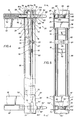
- Fig. 1 represents a general construction component 10 which incorporates improvements in the apparatus described and illustrated in prior U.S. Patents No. 2,876,726, No. 3,057,315, and No. 3,805,721. Such improvements will be described in detail hereinafter. Otherwise, the component 10 and the lock assemblies carried thereby may be assumed to incorporate the various features disclosed in said prior U.S. patents.
- the construction component 10, as shown, is a buoyant type, so that it may be used in constructing floating bridges, barges, floating piers or docks, floating platforms, and the like. It will be appreciated, however, that the component 10, along with similar components, could likewise be used in the construction of various non-floating structures, such as land supported bridges, platforms, etc. Construction components specifically intended for the latter type usage may or may not be made buoyant, as desired.
- component 10 is in the form of a rectangular parallelepiped.
- Component 10 includes an internal force bearing framework, to be described hereinafter, which is generally encased within an outer covering including an upper wall 12, a lower wall 13, and four lateral walls. The lateral walls in turn are subdivided into end walls 14 and side walls 16.
- each corner of the component 10 there is mounted a standard container fitting 18.
- Such fittings are well known, and in particular, are of the same type which are used in the corners of standard freight containers.
- Each of the fittings 18 has three intersecting bores 19 into which lifting tools, lash lines and the like can be inserted for lifting and handling the component 10, lashing it in place in racks on a freighter, and otherwise handling the component 10 in the same manner as standard freight containers are handled.
- the gross dimensions of component 10 measured between the outer surfaces of its various pairs of opposite walls, generally correspond to those of a standard freight container.
- the gross dimensions of component 10 may correspond to those of any of the ISO standard size containers
- the present components could be adapted to other container sizes which may become standard in the future.
- component 10 generally corresponds to those of a standard freight container, it is meant that any projections formed by the container fittings 18 or the various parts of the lock assemblies to be described hereinafter, when those lock assemblies are placed in suitable positions for transport, do not project beyond the outer surfaces of the walls of component 10 by distances such as to interfere with the shipping and handling of component 10 in generally the same manner as a standard freight container.
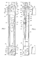
- a plurality of upper and lower male lock assemblies 20 and 20', respectively, and upper and lower female lock assemblies 22 and 22', respectively, are carried adjacent the upper and lower edges of the lateral walls, i.e. end walls 14 and side walls 16.
- the lock assemblies are arranged in tandem pairs, the assemblies of each pair being vertically spaced so that they are disposed respectively adjacent the upper and lower edges of the particular lateral wall on which they are located.
- Terms such as “vertical,” “horizontal,” “top,” “upper,” and “lower” are used herein for convenience; they refer to the apparatus as shown and as normally used, and should not be construed as further limiting the scope.
- each pair are of the same gender, and the male and female assemblies are alternated along the length of each lateral wall, and are of an even number.
- each end wall 14 there are two pairs of assemblies, one pair of male assemblies 20 and 20' and one pair of female assemblies 22 and 22'.
- the male assemblies 20 and 20' on one of the end walls 14 are disposed across from and aligned with the female assemblies 22 and 22' of the other of the end walls 14.
- one end of a component 10 can be aligned with either end of another similar component 10, and the male assemblies of each of said ends will automatically be aligned with the female assemblies of the other of said ends so that the two can be connected.
- a given side of a component 10 can be connected to either side of another similar component 10.
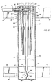
- the construction component 10 includes an internal structural framework which, as more fully described in the aforementioned prior U.S. patents, may include a plurality of interconnected trusses.
- each tandem pair of male assemblies on one side of the construction component is located across from a tandem pair of female assemblies on the other side of the component.
- Such complementary pairs of male and female lock assemblies are mounted at opposite ends of a given transverse truss.
- the truss shown in Fig. 3 includes parallel upper and lower cords 24 and 26, interconnected by struts 28.
- struts 28 are arranged so as to abut cords 24 and 26 at spaced apart locations, so as to enhance the flexibility of the truss.
- rails 30, which space upper wall 12 from the upper extremity of cord 24 and similar cords in other trusses throughout the construction component abut cord 24 at positions spaced longitudinally from those at which the trusses 28 abut cord 24.
- rails 32 which are disposed between the bottom of lower cord 26 and the bottom wall 13 of the construction component are longitudinally spaced from the locations of abutment of struts 28 with cord 26.
- each of the male lock assemblies 20 and 20' of the tandem pair shown includes a body in the form of a housing 34 or 34', respectively.
- Housing 34 will be described in greater detail hereinafter. Housings 34 and 34' are identical, but reversed in orientation so that they are mirror images across a horizontal plane.
- any part of lower male lock assembly 20' which is identical to a part of upper male lock assembly 20 will be designated by the same reference numeral with the character "'" appended thereto.
- the upper and lower male lock assemblies are identical, the lower assembly will not be described in great detail. The same scheme will be utilized in describing upper and lower female lock assemblies 22 and 22'.
- Housing 34 has a front wall 36 located near the outer end of the truss in position for general alignment with the respective side wall 16, and a rear wall 38 spaced therefrom inwardly with respect to the truss.
- Cord 24 is channel-shaped and is welded to one side of the housing 34 of the upper male lock assembly 20 of the tandem pair. Cord 24 is oriented so that its channel faces laterally outwardly with respect to the connected male housing 34.
- the weld lines 40 extend along housing 34 for a substantial distance in the front-rear directional mode. In addition, there is a weld 41 across the end of cord 24.
- cord 42 is welded to the opposite side of the housing 34 from cord 24.
- Cord 42 forms a part of another truss, which is a mirror image of the truss shown in Fig. 3, and which further includes lower cord 44 and interconnecting struts (not shown).
- the housing 34 of the upper male lock assembly 20 is sandwiched between the upper cords 24 and 42 of two adjacent trusses.
- housing 34' of lower male lock assembly 20' is welded between the ends of the lower cords 26 and 44 of the two adjacent trusses.
- a pair of tandem female lock assemblies 22 and 22' each of which includes a female body in the form of a female housing 46 or 46', respectively.
- parts of the male and female lock assemblies which are more or less similar or analogous will be designated “male” or “female” to distinguish between the parts of the two genders of assemblies, and this is not intended to imply that these parts are necessarily of a projecting or receiving type configuration.
- Female housing 46 has a front wall 48 and a rear wall 50 spaced therefrom.
- the weld lines 52 may extend a substantial distance in the front-rear directional mode.
- the female housing 46' of the lower female lock assembly is likewise welded between the ends of cords 26 and 44 opposite those which mount the lower male lock assembly 20'.
- the front wall 36 of male housing 34 has a thickened portion 54 which serves as the male socket means and has rear and front walls 54a and 54b, respectively.
- Male socket means defines a rectangular male socket opening 56 extending therethrough in the front-rear directional mode.
- front-rear directional mode will generally refer to a position or direction of orientation parallel to front-to-rear and rear-to-front directions.
- transverse horizontal dimension of male socket opening 56 is substantially greater than its transverse vertical dimension.
- the male lock assembly 20 further includes a monolithic cast metallic pin member 58 which is slidably received in opening 56 for reciprocation, in the front-rear directional mode, between an advanced position, as shown in Fig. 4, and a retracted position, as shown in Fig. 10.
- the portion of pin member 58 which is received in opening 56 is generally of a complementary rectangular cross-sectional configuration, of greater horizontal dimension than vertical dimension.
- the outermost or head end of pin member 58 is tapered, as shown at 60, to a somewhat smaller rectangular cross section.
- Head end 60 has a notch 61 in its upper surface.
- first lock engagement region or necked down area including a pair of grooves 62 extending vertically along opposite sides of pin member 58 and opening laterally outwardly. Rearward of grooves 62 is the relatively large rectangular portion 64 of pin member 58, forward or rear portions of which are disposed in opening 56, depending upon whether pin member 58 is in its retracted or advanced position.
- Portion 64 of pin member 58 has recesses 66 in its upper and lower surfaces, for a purpose to be described hereinafter. Recesses 66 are not sufficiently large to unduly detract from the load bearing capabilities of portion 64 of pin member 58.
- a second lock engagement region or necked down area including vertical grooves 68 substantially identical to grooves 62.
- Rearward of grooves 68 is a small tapered section 70, which in turn adjoins the cylindrical tail end 72 of the pin member 58. It should be noted that the diameter of tail end 72 does not exceed the vertical dimension of rectangular portion 64 of pin member 58.
- Male lock assembly 20 further comprises lock means in the form of a plate-like lock member 74.
- the male lock member 74 is substantially identical to the female lock member 116 of female lock assembly 22, to be described more fully hereinbelow.
- Figs. 4 and 5 which show male lock member 74 in its lower or locking position
- Figs. 6 and 7, which show the identical female lock member 116 in its upper or release position
- lock member 74 is generally in the form of an inverted U, having downwardly extending tines or rails 76 sized to slidably fit in respective locking grooves 68, or alternatively, in respective locking grooves 62.
- Rails 76 are joined at their upper ends by a bridge section 78.
- a tab 80 extends rearwardly from the upper end of bridge section 78.
- Lock member 74 is disposed just rearwardly of male socket means 54 in sliding abutment with the rear face 54a thereof.
- An opening 84 in the upper wall 35 of male housing 34 allows lock member 74 to be raised from the locking position shown in Fig. 4, wherein rails 76 are disposed in one or the other of the two pair of locking grooves 62 or 68, to a raised release position, wherein the locking member 74 clears the pin member 58.
- a suitable tool such as a crowbar, can be inserted in a notch 84a in opening 84 and engaged under tab 80.
- the lower male lock assembly 20' of the tandem pair has a male housing 34' which is a mirror image of housing 34 across a horizontal plane.
- Assembly 20' further includes a pin member 58' which is identical to the pin member 58 of the upper male lock assembly 20 and oriented in the same manner. Because the pin members 58 and 58' are identical, and because their locking grooves, e.g. 62 and 68, extend completely therethrough in the vertical direction, it is possible for the lock member 75 of lower male lock assembly 20' to be oriented in the same manner as the lock member 74 of upper male lock assembly 20, i.e. with its bridge section uppermost and its rails or tines extending downwardly therefrom. Lock member 75 is identical to lock member 74, except that it lacks the tab 80 and its rails 77 are longer.
- the two lock members 74 and 75 are connected for joint reciprocation between their locking positions and release positions by lock extension means in the form of rods 82 welded to the laterally outer sides of the two male lock members.
- lock extension means in the form of rods 82 welded to the laterally outer sides of the two male lock members.
- the lower end of the housing 34 of the upper male lock assembly, and the identical upper end of the housing 34' of the lower male lock assembly are open to permit the necessary movements of rods 82.
- These open ends of housings 34 and 34' are further rigidly interconnected by body extension means in the form of a channel member 86, as by welding.
- Guides 73 are welded to housing 34' for cooperation with the rear surface of lower male lock member 75.
- a male lock retainer which is substantially identical to the device 61, 62, 63, 64 shown in prior U.S. Patent No. 3,805,721, is provided.
- the device includes a base plate 87 which is welded between the sides of channel 86 in a position to slidably engage the front surfaces of rod 82.
- a nut and bolt assembly 89 connects plate 87 to a spring 88 which is thereby clamped against the rear surfaces of rods 82 to frictionally engage the rods, and thereby, indirectly frictionally engage the lock members 74 and 75.
- the force with which the device 87, 88, 89 frictionally engages rods 82 is generally sufficient to prevent separation of the lock members 74 and 75 from their respective lock assemblies.
- positive stop bars 91 are welded between rods 82, for abutment with blocks 93 carried on plate 87, to positively limit vertical movement and prevent such separation.
- the friction device 87, 88, 89 urges the lock members 74 and 75 forwardly against their respective sockets 54 and 54'.
- friction device 87, 88, 89 will temporarily maintain the tandem lock member 74 and 75 in any position in which they are placed, and in particular, if they are raised, will temporarily maintain them in a raised position against the force of gravity. Nevertheless, the force with which the friction device engages rods 82 is not so great as to interfere with selective manual raising or lowering of the lock members, with simple tools such as crowbars and hammers, when desired.
- an inverted-U-shaped latch spring 90 is mounted on rods 82.
- Spring 90 is substantially identical in structure and function to that of prior U.S. Patent No. 3,805,721, and thus, will not be described in great detail herein. Briefly, spring 90 is biased rearwardly so that, when the locking members 74 and 75 are in their locking positions, as shown in Fig. 4, the upper end of spring 90 is disposed beneath the upper wall 35 of housing 34 just adjacent opening 84. When it is desired to raise the lock members 74 and 75, a tool can be inserted in notch 84a to pry spring 90 forward so that the lock members can be raised. Then, whenever the lock members are again lowered to their locking positions, spring 90 will automatically snap back into a latching position under the upper wall of housing 34.
- the rear wall 38 of housing 34 has a pocket 92 extending rearwardly therefrom for sliding receipt of the tail end 72 of pin member 58.
- a helical compression spring 94 is interposed between the bottom of pocket 92 and a shoulder 96 on the tail end 72 of pin member 58 to bias pin member 58 forward.
- a pin retainer in the form of spring 98 is carried on the underside of pin member 58.
- Spring 98 extends generally longitudinally along pin member 58. Its rear end is anchored on pin member 58, while its forward end is free and biased outwardly away from pin member 58. However, spring 98 can be biased inwardly so that it fits into a groove 100 (see Fig. 9) in the underside of pin member 58.
- spring 94 can be inserted through socket opening 56 and into pocket 92. Pin member 58 is then inserted through socket opening 56, such insertion being permitted by the fact that the vertical dimension of pin member 58 nowhere exceed that which might pass through socket opening 56. As the pin member 58 is being inserted into housing 34 through socket opening 56, spring 98 is cammed inwardly by the lower surface of opening 56 into groove 100. Once groove 100 passes completely through socket opening 56, the forward end of spring 98 will spring outwardly and abut the rear face 54a of socket means 54, thereby preventing pin member 58 from falling back out of opening 56.
- Abutment of spring 98 with rear face 54a of socket means 54 also limits forward movement of pin member 58 under influence of spring 94 to a proper advanced position wherein grooves 68 are positioned for engagement by rails 76 of locking member 74. If it is necessary to disassemble the lock assembly, a suitable tool can be inserted through opening 84 to force spring 98 upwardly into groove 100 until pin member 58 has been advanced sufficiently for spring 98 to be held in its groove 100 by the lower surface of socket opening 56.
- the rear wall 38' of housing 34' of lower male lock assembly 20' has a pocket 92' identical to pocket 92.
- the pin members 58 and 58' of the upper and lower male lock assemblies are identical, and the pin member 58' of the lower male lock assembly 20' has associated therewith springs identical, both in form and in interrelation with other parts of the lock assembly, to springs 94 and 98.
- springs in the lower male lock assembly 20' will not be shown or further described in detail.
- the front wall 36 of housing 34 has a pair of shear bearing lugs 102 formed thereon. Lugs 102 are disposed on opposite sides of socket opening 56. Lugs 102 project forwardly from the remainder of front face 54b of socket means 54, but by a distance sufficiently small that they will not interfere with the handling of the construction component 10 on which the lock assembly is carried in the manner of a standard freight container.
- the upper and lower surfaces 101 of each lug 102 are planar surfaces extending generally horizontally but slightly vertically inclined toward each other for a purpose to be described more fully hereinbelow. Housing 34' of lower male lock assembly 20' has identical lugs 102' thereon.
- upper female lock assembly 22 will be described in greater detail.
- the housing 46 of upper female lock assembly 22 is similar to the housing 34 of upper male lock assembly 20 in many respects.
- Its front wall 48 includes a female socket means 104 having rear face 104a and front face 104b.
- a female socket opening 106 substantially identical in size and shape to opening 56 of male lock assembly 20, extends through socket means 104 in the front-rear directional mode.
- Front wall 48 of housing 46 differs from front wall 36 of housing 34 in that, rather than the lugs 102, wall 48 has a pair of lugs 108 formed thereon and disposed immediately above and below socket opening 106.
- lugs 108 extend completely laterally across the socket means 104.
- each lug 108 could be replaced by a pair of lugs spaced apart by a distance corresponding to socket opening 106.
- Lugs 108 define therebetween a space 110 for receipt of lugs 102.
- the planar surfaces of lugs 108 which define space 110 are slightly vertically inclined to correspond to the taper 101 of lugs 102.
- the rear wall 50 of housing 46 is similar to the rear wall 38 of housing 34 of upper male lock assembly 20 except that it lacks the integral pocket 92.
- the upper wall of housing 46 is similar to that of the male housing 34, and in particular, includes an opening 112 identical to opening 84 and including a notch 112a identical to notch 84a.
- the bottom of housing 46 is identical to that of housing 34, and in particular, is open and is connected by a channel member 114 to the upper end of housing 46' of the lower female lock assembly 22'.
- a female lock member 116 identical to male lock member 74, is mounted for reciprocation with respect to socket means 104 and its socket opening 106 between a raised release position as shown and a locking position in which the rails 118 of locking member 116 are disposed generally on opposite sides of opening 106 and overlapping therewith.
- locking member 116 includes a bridge section 120 connecting the upper ends of rails 118, and a tab 122 extending rearwardly therefrom.
- the structure of member 116 is identical to that of male lock member 74, and the relationships between the member 116 in its locking and release positions, with respect to opening 106, are precisely the same as the analogous positions of members 74 with respect to opening 56.
- Locking member 116 is likewise connected to a similar locking member 117 of the lower female lock assembly 22' by rods 124, by welding, for joint reciprocation between locking and release positions.
- the assembly 116, 124, 117 is identical to the assembly 74, 82, 75 of the tandem male lock assemblies 20 and 20'.
- a frictional retaining device 125, 126, 127 identical to device 87, 88, 89 is provided for assembly 116, 124, 117, as are stops 129, 131 and a latch spring 128, identical to stops 91, 93 and spring 90, both in structure and function.
- the tandem female lock assemblies shown in Figs. 6 and 7 differ in that their housings 46 and 46' are reversed or arranged as mirror images of each other, while their respective locking members 116 and 117 are oriented in the same direction, i.e. with their tines extending downwardly.
- locking member 117 of the lower female lock assembly has longer tines 119 but lacks a tab analogous to tab 122 of member 116.
- the female lock assemblies are identical, and in particular, it is noted that shear bearing lugs 108', identical to lugs 108, are formed on front wall 46', and guides 109 are provided for lower female lock member 117.
- Fig. 10 shows the pin member 58 of upper lock assembly 20 in its retracted position, and the retracted position of the pin member 58' of the lower male lock assembly would be analogous.
- pin member 58 has been forced rearwardly, compressing spring 94, until the grooves 62 of its first lock engagement region are disposed behind the rear face 54a of socket 54 where they are engaged by respective rails 76 of locking member 74, which has been lowered to its locking position.
- rails 76 are sized to project laterally outwardly from grooves 62 beyond the sides of opening 56 so that they may abut the rear face 54a of socket 54.
- the rear-to-front force exerted on pin member 58 by compressed spring 94, or any other rear-to-front force which might be exerted on pin member 58 is transmitted through locking member 74 to socket 54, whereby pin member 58 is prevented from advancing from the position shown in Fig. 10.
- further retraction of pin 58 rearwardly from the position of Fig. 10 is not a particular problem, it might be noted that such movement will be limited by abutment of tab 80 of lock member 74 with the edge of opening 84 in housing 34 and abutment of lock member 75 with guides 73.
- the locking member 74 is latched into its lowered or locking position, as shown, by virtue of the fact that spring 90 underlies the top wall 35 of housing 34 adjacent opening 84. It should be noted that, when the lock member 74 is in its locking position, it lies generally flush with the upper extremity of housing 34, which in turn is generally flush with the top wall 12 of the construction component 10 (shown in Fig. 10 but broken away in other Figs. for clarity).
- the head end of pin member 58 projects forwardly from the front face 54b of socket 54 only by a very small distance, generally comparable to that by which the lugs 102 project. As previously mentioned, this distance is not great enough to interfere with transport and other handling of the construction component 10 in the manner of a standard freight container.
- a crowbar or other suitable tool is inserted into notch 84a in opening 84 in the top wall 35 of housing 34 of the upper male lock assembly 20.
- the tool is used to force the upper end of spring 90 forward, until it clears the underside of the top housing wall and is forced under tab 80.
- tab 80 can be pryed upwardly, thereby raising locking member 74 and the connected locking member 75 of the lower male lock assembly 20'.
- Continued upward movement may be effected, either with the same or another tool, or by hand, once the upward movement has been started in the aforementioned manner.
- pin member 58 When the locking members 74 and 75 have been raised a sufficient distance to clear their respective pin members 58 and 58', i.e. to their release positions (which are analogous to those shown in Figs. 6 and 7 for the female lock assemblies) pin member 58 will be urged outwardly by spring 94, and pin member 58' will likewise be urged outwardly by a similar compression spring (not shown) in pocket 92'. If, for any reason, e.g.
- housing 34' is identical to housing 34, and in particular, has an opening (not shown) in its lower wall identical to opening 84 in the upper wall of housing 34, a similar technique may be used to force pin 58' outwardly or forwardly.
- pin member 58 As the portion of pin 58 which, in its retracted position, is disposed in pocket 92, moves forwardly, spring 98 will automatically emerge from its groove 100 in the underside of pin member 58. Spring will engage rear face 54a of socket 54 when the pin member 58 is in its advanced position, i.e. with grooves 62 located well beyond front face 54b of socket 54 and with grooves 68 located just behind rear face 54a, under influence of spring 94. Although spring 98 would not be sufficient to take high tensile loading, it will stop the movement of pin member 58 in the forward direction under the relatively low force exerted by spring 94, and temporarily hold the pin member 58 in that position until lock member 74 can be lowered to its locking position, as shown in Fig. 4. Pin member 58' has an identical spring (not shown) which similarly stops the forward movement of pin member 58' at its advanced position.
- locking member 74 When locking member 74 is lowered, as by striking it with a hammer, the connected locking member 75 will automatically be lowered therewith. Rails 76 of locking member 74 will enter grooves 68, and rails 77 of locking member 75 will enter analogous grooves in lower pin member 58'. Since locking member 74 is sandwiched between rear face 54a of socket 54 and the edge of upper housing wall 35 adjacent opening 84, and lock member 75 is sandwiched between socket 54' and guides 73, this position locks the pin members in their advanced positions.
- the locking rails 76 or 77 of each pair have their inner sides flared outwardly and downwardly, as explained in the aforementioned prior U.S. patents (see also 118a and 119a in Fig.
- each rail 76 has its front and rear surfaces tapered inwardly and downwardly to guide the rails into the locking grooves.
- the locking members 116 and 117 of the tandem female lock assemblies 22 and 22' will be raised to their release positions, as shown in Figs. 6 and 7, in the same manner as was done with the male lock assemblies. Then, with the male lock assemblies in the positions shown in Figs. 4 and 5, and the female lock assemblies in the positions shown in Figs. 6 and 7, the construction components on which these assemblies are carried are drawn toward each other, as by ropes or the like, so that pin members 58 and 58' enter socket openings 106 and 106', respectively.
- the tapered areas 60 on the head end of pin member 58 help to gradually guide the pin member into the female socket opening 106.
- tapered areas 110 likewise help to gradually guide pin member 58 into socket opening 106. The same type action occurs in the lower lock assemblies 20' and 22'.
- pin member 58 If a rear-to-front tensile force is exerted on pin member 58, e.g. if the construction component on which the female lock assembly 22 is carried tends to pull away from the construction component on which the male assembly 20 is carried, such force will be transmitted from the rear face 104a of socket 104 through locking member 118 to pin member 58, and from pin member 58 through male locking member 74, to male socket 54.
- the shear bearing lugs 102 and 108 of the male and female lock assemblies are meshed. Because the shear bearing formations 102 and 108 project and receive in a generally front-rear directional mode with respect to pin member 58, they are capable of transmitting shear forces transverse to pin member 58 independently of that pin member.
- shear bearing formations which would transmit horizontal shear forces independently of the pin member.
- shear bearing formations be arranged so as to transmit shear loads transverse to the pin member in a direction generally parallel to the path of reciprocation of the locking means, thus they should face generally in such direction.
- the transverse vertical dimension of pin member 58 can be substantially smaller than its transverse horizontal dimension, since pin member 58 is relied upon to transmit only horizontal shear loads (which are usually relatively low in the types of construction in question).
- a given locking system comprising a male and female lock assembly, is capable of handling generally greater loads than were previously possible, without a corresponding increase in the overall size and weight of the pin members.
- by minimizing the vertical thickness of pins 58 and 58' it is possible to maximize the distance between their centers of gravity, and thereby better resist hinging action of the connected components on a horizontal axis.
- the locking system is defined to positively prevent any substantial hinging, about a horizontal axis, as between adjacent connection components. This enables such components to be assembled into many types of structures which could not be properly formed with the articulated types of connections exemplified by certain prior art systems described hereinabove.
- each of the housings 34 and 46 is integral -- preferably monolithic -- and has a substantial front-to-rear dimension, i.e. includes a front wall which defines the respective socket means and a rear wall spaced from that front wall.
- the weld lines 40 and 52 extend along a substantial front-rear extent of the respective housings 34 and 46.
- the new arrangement provides a better force distribution, and in particular, provides a welded attachment at a position spaced from the socket means, where substantial forces are felt, thereby lessening the chance of failure of one type or another.
- the upper female lock member 116 is raised to its release position, carrying the lower female lock member 117 with it via rods 124.
- the construction components can then be separated.
- the female lock members can then be relowered into their locking positions, but without any pin members disposed in their respective sockets.
- the upper male lock member 74 is first raised to its release position, carrying the lower member 75 therewith.
- Lower pin member 58' of the tandem pair of male lock assemblies is pushed rearwardly or inwardly to its retracted position and temporarily held there manually or by any suitable means.
- the interconnected lock members 74 and 75 are partially lowered, by striking the upper member 74. Because the rails 77 of lower male lock member 75 are longer than the rails 76 of upper male lock member 74, rails 77 will engage partially within grooves 62' of their respective pin member 58' while rails 76 of upper lock member 74 are still clear of their respective pin member 58.
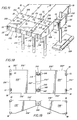
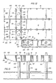
- Figs. 11-13 illustrate one end of a pier or dock which has been constructed using general components 10 together with two types of smaller specialized components, i.e. rake components 200 and spud well components 202 and 204.
- Components 202 have bearing type spud wells, while components 204 have holding type spud wells.
- the difference in this regard is a difference in the function of the particular spud well component in the pier or dock, while the spud well components 202 and 204 are otherwise equivalent in terms of the manner in which they are connected to other components either in a construction project or in a transport assembly such as is described more fully below.
- Figs. 11-13 The structure of Figs. 11-13 is only one example of the many uses which can be made of a construction assembly according to the present invention.
- a pier or dock has been constructed with the major portion of its length being formed by general components 10 arranged in spans three abreast. Only the outermost span is shown. It will be understood that there will be as many spans of general components 10 as necessary to construct the dock or pier to the desired length.
- the bearing spud well components 202 are each in the form of a rectangular parallelepiped having a rectangular top 206, a bottom 208 and four lateral sides including two relatively long sides 210 lying opposite each other, and two shorter sides 212, likewise lying opposite each other.
- Each of the components 202 also has a well or throughway 214 extending vertically therethrough, i.e. through its top 206 and its bottom 208.
- the longer sides 210 of components 202 each carry two pair of lock assemblies of the type described in detail hereinabove, more specifically, a vertically spaced pair of male lock assemblies, upper ones of which are shown at 20, and a pair of vertically spaced female lock assemblies, upper ones of which are shown at 22.
- Each of the male lock assemblies 20 lies directly across from a female lock assembly 22, and the spacing between the male and female lock assemblies on a given side 210 of the component is the same as the lateral spacing between pairs of lock assemblies on the general component 10.
- each of the bearing spud well components 202 has one of its longer sides 210 connected to the end wall of a respective one of the general components 10 in the outermost span of the pier.
- Elongate spuds in the form of pilings 216 extend through the wells 214 of respective components 202 and into load bearing relation with the bottom of the body of water over which the pier lies.
- An interlocking means 218, is installed in each well 214 to interlock the respective component 202 to the respective spud 216, so that the weight of components 202 and adjacent components to which they are attached is borne by the spuds 216.
- Suitable interlocking devices are well known in the art.
- spuds 216 might simply be pinned or welded to components 202. Therefore, members 218 have been shown only diagrammatically, and will not be described in detail herein.
- Figs. 11-13 show only one span of bearing spud well components 202. It should be understood that, throughout the length of the pier or dock whose outer end is shown in the figures, spans of bearing spud well components 202 could be interconnected between spans of general components 10 to provide load bearing capacity at as many points as necessary along the length of the pier. As alternatives to, or in conjunction with such spans of bearing spud well components, and depending on the parameters of the pier or other structure, bearing spud well components 202 could be used at the outboard sides of the spans of general components 10.
- Holding spud well component 204 is virtually identical to the bearing spud well components 202, except that its well 220 need not be adapted to cooperate with an interlocking member to allow the vertical load of the component to be placed on the spud 222 which extends through well 220. Rather, the well 220 need only laterally retain or hold spud 222.
- Spud 222 in turn extends through a hole 224 of a floating bumper member 226 and into the floor of the body of water therebelow.
- spuds 222 laterally position bumper member 226 with respect to the pier and also laterally position the pier with respect to the floor of the body of water. Bumper 226 provides an appropriate abutment for vessels docking at the pier.
- component 204 is identical to component 202, and in particular, includes the same number and arrangement of male and female lock assemblies 20, 20', 22 and 22', whereby it is connected to the outermost side of one of the general components 10.
- a respective rake component 200 is connected to the outermost side 210 of each of the load bearing spud well components 202.
- Each rake component 200 has a rectangular top 228 and four lateral sides lying perpendicular to top 228, more specifically, a pair of opposite longer sides 230 and a pair of shorter sides 232 and 234.
- the bottom 236 of each of the rake components 200 is tapered or graduated, so that the rake component has a deep end adjacent side 234, of the same depth as the other components 10, 202 and 204, and a shallow end adjacent side 232, which forms the outermost extremity of the pier or dock.
- the term "rake component” will generally refer to the types of components illustrated at 200 as well as to ramp-like components which are tapered even more to form a more nearly pointed shallow end.
- each rake component 200 has a pair of vertically spaced male lock assemblies 20 and 20', and a pair of vertically spaced female lock assemblies 22 and 22'.
- the vertical spacing of the lock assemblies in each such pair is the same as that between the components of the various tandem pairs described thus far, and the lateral spacing between the male and female components on side 234 is likewise similar to the lateral spacing between adjacent pairs of lock assemblies in the components described hereinabove.
- each rake component 200 can be locked to a respective bearing spud well component 202 as illustrated.
- the side 232 of the rake component 200 adjacent the shallow end thereof likewise carries a tandem pair of male lock assemblies 20 and 20' and a tandem pair of female lock assemblies 22 and 22'. Because of the shallow depth of the adjacent end of the rake component, the lock assemblies in each of the two pair carried on side 232, while still vertically spaced apart, are not spaced by as great a distance as the lock assemblies in the other pairs described thus far. This is not disadvantageous in the dock or pier structure, since rake components 200 usually either define a free end of such a structure, as shown, or are connected, shallow end to shallow end, with similar rake components.
- a major use of the lock assemblies on side 232 of the rake component 200 is in connecting two such rake components together to form a transport assembly.
- a preferred form of such a transport assembly is shown in Figs. 14 and 15. It can be seen that two rake components 200 have been connected together, with their sides 232 facing each other, utilizing the lock assemblies 20, 20', 22 and 22' on those sides.
- each rake component 200 which is measured horizontally parallel to sides 232 and 234, e.g. adjacent top 228, is generally equal to the width of a standard freight container.
- Figs. 16 and 17 show another transport assembly of two rake components which might be used, for example, if the rake components in question have their shallow ends equipped with some type of fitting or accoutrement, diagrammatically illustrated at 242, which protrudes horizontally from the shallow end, and thereby prevents the shallow ends of the two components from being directly connected together by their lock assemblies.
- the scheme of Figs. 16 and 17 could also be used where it is desired to handle, in the manner of a standard freight container, an assembly of two rake components, where the length of each such component is somewhat less than half the length of a standard freight container.
- the transport assembly of Figs. 16 and 17 comprises two rake components 200', which are identical to components 200 except in size and except for the provision of fittings 242.
- the two components 200' are placed with those sides 232' which lie adjacent their respective shallow ends, facing each other, but not abutting.
- Sides 232' are connected by means of the male and female lock assemblies carried thereon, but rather than being directly connected, they are connected by spacers in the form of struts 244.
- Each strut 244 has a pair of male lock assemblies 20 and 20' at one end thereof, and a pair of female lock assemblies 22 and 22' at the opposite end.
- each strut 244 has one end connected to a pair of lock assemblies on one of the rake components 200', and the other end connected to a pair of lock assemblies on the other of the two rake components 200'.
- each of the components 200' i.e. that dimension which is measured horizontally and parallel to sides 230', is less than half the length of a standard freight container, but greater than one-third the length of a standard freight container.
- the length of the spacers or struts 244 is chosen so that the length of the complete transport assembly is generally equal to that of a standard freight container.
- the first dimension, measured horizontally parallel to sides 232' and 234' has a maximum value (and in this case a constant value) approximately equal to the width of a standard freight container.
- the transport assembly includes two rake components 200'' which, except for length and manner of connection in the assembly, are identical to components 200.
- the sides 232'' of these modified components adjacent their shallow ends carry, toward one lateral edge, a clevis 246, and toward the other lateral edge, a tongue 248.
- each tongue 248 can be received in the clevis 246 of the opposite component. Then, the tongues and clevises can be pinned together by pins 250, held in place in any suitable manner, as well known in the art.
- pins 250 and the mating holes in tongues 248 and clevises 246 are square in transverse cross section. Suitable bracing members may be used to supplement the anti-pivoting effect of pins 250.
- each component 200'' measured horizontally and parallel to sides 232'' and 234'', has a maximum value approximately equal to the width of a standard freight container.
- the dimensions of the tongue and clevis connections 246, 248, when mated, and measured in the same direction as said second dimension, is such as to make the overall length of the transport assembly approximately equal to that of a standard freight container.
- a transport assembly comprised of spud well components.
- the assembly illustrated is comprised of bearing spud well components 202.
- similar assemblies could be formed utilizing holding spud well components 204, or combinations of the two types of spud well components.
- each component 202 which is measured horizontally and parallel to its longer sides 210, is equal to the width of a standard freight container.
- Said sides 210 of the components are also the sides which carry the lock assemblies 20, 20', 22 and 22'.
- an assembly can be built up to have gross dimensions generally corresponding to those of a standard freight container. It is particularly convenient to simply connect adjacent components together utilizing the same lock assemblies 20, 20', 22 and 22', which are used to connect the components to other components in construction jobs.
- any male lock assemblies which are facing outwardly and unused in the transport assembly should have their pins placed in the retracted or low profile positions.
- each of the components 202 is already generally in the form of a rectangular parallelepiped, such sizing permits the assembly to be formed without the need for spacers or the like.
- each component could be made approximately one-fourth the length of a standard freight container, with four components being connected together to form each transport assembly.
- the requirements for sizing can be generalized as follows:
- Each such component must have a first horizontal dimension with a maximum value generally equal to C1/x, where C1 is the width of a standard freight container, and x is greater than or equal to 1.
- the first dimension of each component must be less than or equal to the width of the standard freight container.
- x be a whole number, and in most cases, that x be equal to 1.
- each of the general components 10 can be shipped and handled as a single freight container, while the rake components 200 can be formed into transport assemblies by twos, and the spud well components 202 and 204 can be formed into transport assemblies by fives. Each such transport assembly is likewise shipped and handled in the manner of a standard freight container, but without the need for trying to place these components within actual freight containers.
Landscapes
- Engineering & Computer Science (AREA)
- Mechanical Engineering (AREA)
- Civil Engineering (AREA)
- Structural Engineering (AREA)
- General Engineering & Computer Science (AREA)
- Ocean & Marine Engineering (AREA)
- Architecture (AREA)
- Chemical & Material Sciences (AREA)
- Combustion & Propulsion (AREA)
- Environmental & Geological Engineering (AREA)
- Connection Of Plates (AREA)
- Bridges Or Land Bridges (AREA)
- Packaging Of Annular Or Rod-Shaped Articles, Wearing Apparel, Cassettes, Or The Like (AREA)
- Package Frames And Binding Bands (AREA)
- Revetment (AREA)
Claims (53)
- Ein Transportsystem für das Bauwesen, das aus mindestens einer Transporteinheit besteht, wobei die genannte Einheit mindestens zwei Bauteile (200, 200', 202) enthält,
von denen jedes:
ein erstes allgemein seitliches Gesamtmaß mit einem maximalen Wert aufweist, der im allgemeinen C₁/x entspricht, wobei C₁ die Breite eines mit ISO-Normen übereinstimmenden Frachtcontainers darstellt und x größer als oder gleich 1 ist;
ein zweites allgemein seitliches Gesamtmaß aufweist, das senkrecht zu dem genannten ersten Gesamtmaß steht, und einen maximalen Wert besitzt, der im allgemeinen C₂/y entspricht, wobei C₂ die Länge eines mit ISO-Normen übereinstimmenden Frachtcontainers darstellt und y größer als 1 ist;
sich mindestens eines der genannten ersten und zweiten Maße von den Längen und Breiten aller ISO-Normen entsprechenden Frachtcontainer durch eine Größe unterscheidet, die ausreichend ist, um zu verhindern, daß das Teil alleine als ein ISO-Normen entsprechender Frachtcontainer behandelt wird;
ein drittes allgemein vertikales Gesamtmaß aufweist, das senkrecht zu den genannten ersten und zweiten Maßen steht;
eine allgemein rechtwinklige obere Wand (228, 228', 206) aufweist, an der die genannten ersten und zweiten Maße die genannten maximalen Werte besitzen;
mindestens eine erste Seite (232, 232', 210) aufweist, die nach unten von genannter oberer Wand (228, 228', 206) abhängt und in Richtung auf die genannten ersten und dritten Maße verläuft;
ISO-Normen entsprechende Vorrichtungen (18) zum Heben/Festzurren an jeder der vier Ecken der genannten oberen Wand (228, 228', 206) aufweist;
und entriegelbare Verbindungsvorrichtungen (20, 22) auf den genannten zwei Teilen (200, 200', 202) aufweist, die von den genannten Vorrichtungen (18) zum Heben/Festzurren getrennt und funktional unabhängig von diesen sind, wobei die genannten Verbindungsvorrichtungen (20, 22) zwar selbständig sind, jedoch allgemein innerhalb der Gesamtabmessungen der genannten Teile (200, 200', 202) liegen;
die genannten zwei Teile (200, 200', 202) mittels der genannten Verbindungsvorrichtungen (20, 22) in der genannten Einheit verbunden sind, wobei die genannten ersten Seiten (232, 232', 210) entgegengesetzt ausgelegt und die genannten oberen Wände (228, 228', 206) ausgerichtet sind;
und wobei die genannte Einheit Gesamtabmessungen aufweist, die im allgemeinen jenen eines mit ISO-Normen übereinstimmenden Frachtcontainers entsprechen. - System nach Anspruch 1, worin jedes der genannten zwei Teile (200, 200', 202) vier Seiten (230, 232, 234, 230', 232', 234', 234'', 210, 212) aufweist, einschließlich genannter erster Seite (232, 232', 210), welche senkrecht zu genannter oberer Wand (228, 228', 206) steht.
- System nach Anspruch 2, worin jedes der genannten zwei Teile (200, 200', 202) solche Verbindungsvorrichtungen (20, 22) auf der genannten ersten Seite (232, 232', 210) und auf einer zweiten der genannten Seitenwände (234, 234', 210) gegenüber der genannten ersten Seite (232, 232', 210) besitzt.
- System nach Anspruch 2, worin die genannten Verbindungsvorrichtungen (20, 22) von mindestens einem der genannten zwei Teile (200, 200', 202) ein gekeiltes Verriegelungsteil (20) enthalten, einschließlich eines unbiegsamen Stiftelements (58, 58'), das sich von genannter erster Seite (232, 232', 210) aus erstreckt; und worin die genannten Verbindungsvorrichtungen (20, 22) des anderen der genannten zwei Teile (200, 200', 202) ein genutetes Verriegelungsteil (22) enthalten, einschließlich eines Hohlkörpers (46, 46') mit einer Aufnahmevorrichtung (104), die eine Aufnahmeöffnung (106, 106') begrenzt, welche für die Aufnahme eines solchen Stiftelements (58, 58') bestimmt ist, sowie eine hohle Verriegelung (116), die zwischen einer Entriegelungsstellung und einer Verriegelungsstellung zum selektiven Verriegeln eines solchen Stiftelements (58, 58') in der genannten Aufnahmevorrichtung (104) bezüglich der Aufnahmevorrichtung (104) beweglich ist.
- System nach Anspruch 4, worin jedes der genannten zwei Teile (200, 200', 202) eine Vielzahl von genannten gekeilten Verriegelungsteilen (20) und eine Vielzahl von genannten genuteten Verriegelungsteilen (22) umfaßt.
- System nach Anspruch 5, worin die genannten gekeilten Verriegelungsteile (20) paarweise angeordnet und die beiden gekeilten Verriegelungsteile (20) jedes der genannten Paare über die entsprechende Seite des entsprechenden Teils (200, 200', 202) vertikal voneinander entfernt sind, und wobei die genannten genuteten Verriegelungsteile (22) paarweise angeordnet und die zwei genuteten Verriegelungsteile (22) jedes der genannten Paare über die entsprechende Seite des entsprechenden Teils (200, 200', 202) gleich weit vertikal voneinander entfernt sind wie ein Paar der genannten gekeilten Verriegelungsteile (20).
- System nach Anspruch 6, worin das Stiftelement (58, 58') jedes der genannten gekeilten Verriegelungsteile (20) zwischen einer vorgeschobenen Position, in der das genannte Stiftelement (58, 58') von der entsprechenden Seite des genannten Teils (200, 200', 202) vorragt, und einer zurückgezogenen Position, in der das genannte Stiftelement (58, 58') im allgemeinen innerhalb der Gesamtmaße des genannten Teils (200, 200', 202) liegt, in bezug auf das entsprechende Teil (200, 200', 202) hin- und herbewegt wird.
- System nach Anspruch 7, worin die genannten Stiftelemente (58, 58') und die genannten Verriegelungsteile (116) zwischen ihren entsprechenden Positionen von Hand zu bewegen sind.
- System nach Anspruch 7, worin jedes der genannten gekeilten Verriegelungsteile (20) folgendes umfaßt:
einen Einsteckkörper (34, 34'), einschließlich einer Einsteckvorrichtung (54, 54') mit einer Vorder- (54b) und einer Rückseite (54a) und einer Einstecköffnung (56, 56'), die von vorne nach hinten durch diese hindurch verläuft und das genannte Stiftelement (58, 58') für die genannte Hin- und Herbewegung aufnimmt;
und die Einsteck-Verriegelung (74, 75) wird von dem genannten Einsteckkörper (34, 34') für die Hin- und Herbewegung in bezug auf die genannte Einsteckvorrichtung (54, 54') und quer zu der genannten Einstecköffnung (56, 56') zwischen einer Verriegelungsposition, in welcher es zum Eingriff zwischen genanntem Einsteckkörper (34, 34') und genanntem Stiftelement (58, 58') kommt, um von hinten nach vorne wirkende Kräfte von dem genannten Stiftelement (58, 58') auf den genannten Körper (34, 34') zu übertragen, und einer Entriegelungsposition getragen;
und worin genanntes Stiftelement (58, 58') einen ersten (62) und einen zweiten (68) Verriegelungsbereich aufweist, die über die Länge des genannten Stiftelements (58, 58') räumlich voneinander getrennt sind, so daß, wenn sich genanntes Stiftelement (58, 58') in seiner vorgeschobenen Position befindet, sich genannter erster Verriegelungsbereich (62) vor der genannten Vorderseite (54b) der genannten Einsteck-Vorrichtung (54, 54') befindet, um in eine Aufnahmeöffnung (106, 106') eingesetzt zu werden und mit einer hohlen Verriegelung (116) eines anderen solchen Bauteils (200, 200', 202) in Eingriff zu kommen, und sich genannter zweiter Verriegelungsbereich (68) in einer solchen Position befindet, daß die genannte Einsteck-Verriegelung (74, 75) eingreifen kann, wobei genannte Einsteck-Verriegelung (74, 75) in ihrer Verriegelungsposition mit dem genannten Stiftelement (58, 58') und dem genannten Einsteckkörper (34, 34') zusammenwirkt, um so von hinten nach vorne wirkende Kräfte zu übertragen und eine Vorwärtsbewegung des genannten Stiftelements (58, 58') bezüglich genannter Einsteckvorrichtung (54, 54') über seine vorgeschobene Position hinaus zu verhindern. - System nach Anspruch 9, worin - wenn sich genanntes Stiftelement (58, 58') in seiner vorgeschobenen Position und sich genannte Einsteck-Verriegelung (74, 75) in ihrer Verriegelungsposition befindet - genannte Einsteck-Verriegelung (74, 75) weiter mit genanntem Stiftelement (58, 58') und genanntem Einsteckkörper (34, 34') zusammenwirkt, um eine Bewegung des genannten Stiftelements (58, 58') in Richtung auf seine zurückgezogene Position zu verhindern.
- System nach Anspruch 10, worin - wenn sich genanntes Stiftelement (58, 58') in seiner zurückgezogenen Position befindet - sich der genannte erste Verriegelungsbereich (62) in einer solchen Position befindet, daß die genannte Einsteck-Verriegelung (74, 75) eingreifen kann, wobei genannte Einsteck-Verriegelung (74, 75) in ihrer Verriegelungsposition mit dem genannten Stiftelement (58, 58') und dem genannten Einsteckkörper (34, 34') zusammenwirkt, um eine Bewegung des genannten Stiftelements (58, 58') in Richtung auf seine vorgeschobene Position zu verhindern.
- System nach Anspruch 9, worin sich genannte Einsteck- (74, 75) und hohle (116) Verriegelungen ähnlich sind.
- System nach Anspruch 12, worin jedes der genannten Stiftelemente (58, 58') in jedem seiner Verriegelungsbereiche (62, 68) ein Paar paralleler Verriegelungsrillen (62, 68) aufweist, die allgemein vertikal entlang den gegenüberliegenden Seiten des genannten Stiftelements (58, 58') verlaufen; und worin jede der genannten Einsteck- (74, 75) und hohlen (116) Verriegelungen ein Paar allgemein vertikal ausgerichteter Verriegelungsschienen (76, 77, 118) umfaßt, die hinter der Rückseite (54a, 104a) der entsprechenden Einsteck- oder Aufnahmevorrichtung (54, 54', 104) angeordnet sind, wobei jede der genannten Verriegelungsschienen (76, 77, 118) gleitend in einer entsprechenden Verriegelungsrille (62, 68) eines solchen Rillenpaars aufgenommen werden kann und sich seitlich nach außen von der genannten Rille (62, 68) über die entsprechende Einsteckvorrichtung (56, 56', 106, 106') hinaus erstreckt, wodurch die genannten Verriegelungsschienen (76, 77, 118) an die Rückseite (54a, 104a) der entsprechenden Einsteckvorrichtung (54, 54', 104) neben der entsprechenden Einstecköffnung (56, 56', 106, 106') stoßen kann, um auf das genannte Stiftelement (58, 58') wirkende Längskräfte auf die genannte Einsteckvorrichtung (54, 54', 104) zu übertragen.
- System nach Anspruch 12, worin jede der genannten Einsteck-Verriegelungen (74, 75, 116) in ihrer Verriegelungsposition allgemein innerhalb der Gesamtabmessungen des entsprechenden Teils (200, 200', 202) liegt.
- System nach Anspruch 13, worin die Einsteck-Vorrichtungen (54, 54', 104) jedes Paars von Verriegelungsteilen (20, 22) strukturell miteinander verbunden sind und die Einsteck-Verriegelungen (74, 75, 116) jedes Paars von Verriegelungsteilen (20, 22) zum Zwecke der gemeinsamen Hin- und Herbewegung verbunden sind.
- System nach Anspruch 9, worin die genannten gekeilten (20) und genuteten (22) Verriegelungsteile entsprechende Scherlagenformationen (102, 102', 108, 108') aufweisen, die einstückig mit ihren entsprechenden Einsteckvorrichtungen (54, 54', 104) verbunden sind, wobei die genannten Scherlagerformationen (102, 102', 108, 108') zum Ineinandergreifen horizontal vorstehen und aufnehmen, wenn das entsprechende Verriegelungsteil (20, 22) mit einem passenden Verriegelungsteil (22, 20) eines anderen solchen Bauteils zusammengesteckt wird, und entsprechende gegenüberliegende Scherlagerflächen definieren, um die quer auf das genannte Stiftelement (58, 58') einwirkenden Scherkräfte unabhängig von dem genannten Stiftelement (58, 58') zu übertragen.
- System nach Anspruch 16, worin die genannten Scherlagerformationen (102, 102', 108, 108') auf diese Weise vertikale Scherbelastungen übertragen und in der Lage sind, einer Schwenkbewegung von Teilen (200, 200', 202), die mit solchen zusammengesteckten Verriegelungsteilen verbunden sind, um eine horizontale Achse zu widerstehen.
- System nach Anspruch 16, worin jedes der genannten Verriegelungsteile (20, 22) ein Gehäuse (34, 34', 46, 46') mit einer Vorderwand (36, 36', 48) umfaßt, welche die entsprechenden Einsteck- und Aufnahmevorrichtungen (54, 54', 104) aufweist und auf der die entsprechenden Scherlagerformationen (102, 102', 108, 108') gebildet sind, und eine Rückwand (38, 38', 50), die von der genannten Vorderwand beabstandet ist.
- Einrichtung nach Anspruch 18, worin jedes der genannten Gehäuse (34, 34', 46, 46') monolithisch ist.
- System nach Anspruch 2, worin das genannte Bauteil (200, 200', 202) schwimmfähig ist.
- System nach Anspruch 2, worin die genannten zwei Bauteile Rechenteile (200, 200') sind, von denen jedes eine Unterseite (236, 236') gegenüberliegend der genannten Oberseite (228, 228'), welche stufenartig verläuft, aufweist, so daß sich die genannte dritte Abmessung von den genannten ersten oder zweiten Abmessungen unterscheidet, wobei das genannte Rechenteil (200, 200') ein tiefes und ein flaches Ende besitzt.
- System nach Anspruch 21, worin sich die genannte dritte Abmessung von der genannten zweiten Abmessung unterscheidet, und die genannte erste Seite (232, 232') an dem genannten flachen Ende gelegen ist, wobei die flachen Enden der zwei Teile so mittels Verbindungsvorrichtungen (20, 22) in der genannten Transporteinheit verbunden sind und einander gegenüberliegen.
- System nach Anspruch 22, worin die genannten Verbindungsvorrichtungen (20, 22) direkt an den flachen Enden der genannten zwei Rechenteile (200, 200') verbunden sind, und worin y eine ganze Zahl ist.
- System nach Anspruch 23, worin y gleich 2 ist.
- System nach Anspruch 24, worin x gleich 1 ist.
- System nach Anspruch 22, worin die genannte Transporteinheit ebenso Distanzvorrichtungen (244) umfaßt, die Verbindungsvorrichtungen (20', 22') tragen, welche kompatibel mit den Verbindungsvorrichtungen (20, 22) der genannten zwei Rechenteile (200, 200') sind, und die genannten flachen Enden der genannten zwei Rechenteile (200, 200') indirekt mittels der genannten Distanzvorrichtungen (20, 22) innerhalb der genannten Einheit verbunden sind.
- System nach Anspruch 26, worin y kleiner als 2 ist.
- System nach Anspruch 27, worin x gleich 1 ist.
- System nach Anspruch 2, worin die genannten zwei Teile Spudding-Teile (202) sind, von denen jedes einen Durchgang (214, 220) aufweist, durch welchen sie in Richtung auf die genannte dritte Abmessung zur Aufnahme eines länglichen Spudelements (216, 222) verlaufen.
- System nach Anspruch 29, worin mehr als die zwei genannten Spudding-Teile (202) in der genannten Einheit vorhanden sind.
- System nach Anspruch 29, worin die genannten ersten Seiten (210) der genannten zwei Spudding-Teile (202) direkt mittels der genannten Verbindungsvorrichtungen (20, 22) in der genannten Einheit verbunden sind.
- System nach Anspruch 31, worin x gleich 1 und y eine ganze Zahl kleiner als 1 ist.
- System nach Anspruch 29 umfaßt mindestens ein allgemeines Bauteil (10) in Form eines allgemein rechtwinkligen Quaders, das Gesamtmaße, die im allgemeinen denen eines mit ISO-Normen übereinstimmenden Frachtcontainers entsprechen, und Verbindungsvorrichtungen (20, 22) aufweist, die kompatibel mit jenen der genannten Spudding-Teile (202) sind.
- System nach Anspruch 33, worin das genannte allgemeine Teil (10) solche Verbindungsvorrichtungen (20, 22) auf allen vier seiner Seitenwände (14, 16) aufweist.
- System nach Anspruch 2, worin x eine ganze Zahl ist.
- System nach Anspruch 35, worin x gleich 1 ist.
- System nach Anspruch 36, worin y kleiner als oder gleich 2 ist.
- System nach Anspruch 37, worin y eine ganze Zahl ist.
- System nach Anspruch 2, worin die genannten zwei Teile der genannten Einheit Spezialteile (200, 200', 202) sind, wobei das genannte System ebenso mindestens ein allgemeines Bauteil (10) in Form eines allgemein rechtwinkligen Quaders, das Gesamtmaße, die im allgemeinen denen eines mit ISO-Normen übereinstimmenden Frachtcontainers entsprechen, und Verbindungsvorrichtungen (20, 22) aufweist, die kompatibel mit jenen der genannten Spezialteile (200, 200', 202) sind.
- System nach Anspruch 1, worin die genannten Teile (200, 200', 202) auseinandergenommen werden können, um die genannte Einheit zu zerlegen, wobei sie mit anderen Bauteilen (10, 200, 200', 202, 204) in einer verschiedenen Konfiguration zur Konstruktion einer Lastträgerstruktur verbunden werden können.
- System nach Anspruch 40, worin mindestens einige solcher Verbindungsvorrichtungen (20, 22) auf den genannten ersten Seiten (232, 232', 210) der genannten Teile gelegen sind, und die genannten ersten Seiten (232, 232', 210) mittels Verbindungsvorrichtungen (20, 22) in der genannten Einheit verbunden sind.
- System nach Anspruch 41, worin die genannten ersten Seiten (232, 232', 210) in der genannten Eineit direkt verbunden sind.
- System nach Anspruch 41, worin die genannten ersten Seiten (232') in der genannten Transporteinheit indirekt über Distanzvorrichtungen (244) verbunden sind.
- System nach Anspruch 41, worin die genannten Verbindungsvorrichtungen (20, 22) die genannten Teile (10, 200, 200', 202, 204) in der genannten verschiedenen Konfiguration so verbinden können.
- System nach Anspruch 44, worin jedes der genannten Teile (10, 200, 200', 202, 204) ein schwimmfähiger Ponton ist.
- Ein Transportsystem für das Bauwesen, das aus mindestens einer Transporteinheit besteht, wobei die genannte Einheit mindestens zwei Bauteile (200, 200', 200'', 202) enthält,
von denen jedes (200, 200', 200'', 202):
ein erstes Gesamtmaß mit einem maximalen Wert aufweist, der im allgemeinen C₁/x entspricht, wobei C₁ die Breite eines mit ISO-Normen übereinstimmenden Frachtcontainers darstellt und x größer als oder gleich 1 ist;
ein zweites Gesamtmaß aufweist, das senkrecht zu genanntem ersten Gesamtmaß steht, und einen maximalen Wert besitzt, der im allgemeinen C₂/y entspricht, wobei C₂ die Länge eines mit ISO-Normen übereinstimmenden Frachtcontainers darstellt und y größer als 1 ist;
sich mindestens eines der genannten ersten und zweiten Maße von den Längen und Breiten aller ISO-Normen entsprechenden Frachtcontainer durch eine Größe unterscheidet, die ausreichend ist, um zu verhindern, daß das Teil alleine als ein ISO-Normen entsprechender Frachtcontainer behandelt wird;
ein drittes Gesamtmaß aufweist, das senkrecht zu genannten ersten und zweiten Maßen steht;
mindestens eine erste Seite (232, 232', 232'', 210) aufweist, die in Richtung auf die genannten ersten und dritten Maße verläuft;
und entriegelbare Verbindungsvorrichtungen (20, 22) auf den genannten zwei Teilen (200, 200', 200'', 202) aufweist;
genannte zwei Teile (200, 200', 200'', 202) mittels genannter Verbindungsvorrichtungen (20, 22) in der genannten Einheit verbunden sind, wobei die genannten ersten Seiten (232, 232', 232'', 210) entgegengesetzt ausgelegt sind;
und wobei die genannte Einheit Gesamtabmessungen aufweist, die im allgemeinen jenen eines mit ISO-Normen übereinstimmenden Frachtcontainers entsprechen;
und die genannten Teile (200', 200'', 202) können auseinandergenommen werden, um die genannte Einheit zu zerlegen, wobei sie mit anderen Bauteilen in einer verschiedenen Konfiguration zur Konstruktion einer Lastträgerstruktur verbunden werden können. - Ein Transportsystem für das Bauwesen, das aus mindestens einer Transporteinheit besteht, wobei die genannte Einheit mindestens zwei Bauteile (200, 200', 200'', 202) in Form eines schwimmfähigen Pontons enthält,
von denen jedes:
ein erstes Gesamtmaß mit einem maximalen Wert aufweist, der im allgemeinen C₁/x entspricht, wobei C₁ die Breite eines mit ISO-Normen übereinstimmenden Frachtcontainers darstellt und x größer als oder gleich 1 ist;
ein zweites Gesamtmaß aufweist, das senkrecht zu dem genannten ersten Gesamtmaß steht, und einen maximalen Wert besitzt, der im allgemeinen C₂/y entspricht, wobei C₂ die Länge eines mit ISO-Normen übereinstimmenden Frachtcontainers darstellt und y größer als 1 ist;
sich mindestens eines der genannten ersten und zweiten Maße von den Längen und Breiten aller ISO-Normen entsprechenden Frachtcontainer durch eine Größe unterscheidet, die ausreichend ist, um zu verhindern, daß das Teil alleine als ein ISO-Normen entsprechender Frachtcontainer behandelt wird;
ein drittes Gesamtmaß aufweist, das senkrecht zu den genannten ersten und zweiten Maßen steht;
mindestens eine erste Seite (232, 232', 232'', 210) aufweist, die in Richtung auf die genannten ersten und dritten Maße verläuft;
und entriegelbare Verbindungsvorrichtungen (20, 22) auf den genannten zwei Teilen aufweist;
genannte zwei Teile (200, 200', 200'', 202) mittels genannter Verbindungsvorrichtungen (20, 22) in der genannten Einheit verbunden sind, wobei die genannten ersten Seiten (232, 232', 232'', 210) entgegengesetzt ausgelegt sind;
und wobei die genannte Einheit Gesamtabmessungen aufweist, die im allgemeinen jenen eines mit ISO-Normen übereinstimmenden Frachtcontainers entsprechen. - Ein Transportsystem für das Bauwesen, das aus mindestens einer Transporteinheit besteht, wobei die genannte Einheit mindestens zwei Spudding-Bauteile (102, 104) enthält und jedes der genannten Teile im allgemeinen die Form eines rechtwinkligen Quaders aufweist und;
einen Durchgang (214, 220) besitzt, der zur Aufnahme eines länglichen Spudelements (216, 222) vertikal durch das genannte Teil verläuft;
eine Breite besitzt, die im allgemeinen C₂/y entspricht, wobei C₂ die Länge eines mit ISO-Normen übereinstimmenden Frachtcontainers darstellt und y eine ganze Zahl ist;
eine Länge besitzt, die im allgemeinen der Breite eines mit ISO-Normen übereinstimmenden Frachtcontainers entspricht;
entriegelbare Verbindungsvorrichtungen (20, 22) auf mindestens einigen der länglichen Seiten (210) der genannten Teile (202) aufweisen;
die Anzahl y solcher Teile (202), die nebeneinander durch die genannten Verbindungsvorrichtungen (20, 22) in der genannten Einheit verbunden sind. - Eine Transport- und Baumethode, die aus folgenden Schritten besteht:
Verbindung von mindestens zwei Bauteilen (200, 200', 200'', 202), um eine Transporteinheit mit Gesamtabmessungen zu bilden, die im allgemeinen jenen eines mit ISO-Normen übereinstimmenden Frachtcontainers entsprechen;
Transport der Einheit zu einer Baustelle mittels eines ISO-Normen entsprechenden Frachtcontainers;
Zerlegung der Teile (200, 200', 200'', 202) der Einheit; und
Wiedervereinigung der genannten Teile (200, 200', 200'', 202) mit anderen Teilen (200, 200', 200'', 202) in einer sich von der Transporteinheit unterscheidenden Konfiguration zur Bildung einer Struktur. - Methode nach Anspruch 49, worin:
die genannten zwei Teile Rechenteile (200, 200', 200'') sind, von denen jedes eine Unterseite (236, 236', 236''), welche stufenartig verläuft, aufweist, wobei das Rechenteil (200, 200', 200'') ein tiefes und ein flaches Ende besitzt; und
die zwei Rechenteile (200, 200', 200'') in der genannten Transporteinheit so verbunden sind, daß ihre flachen Enden nebeneinander und einander gegenüberliegen, wobei ihre tiefen Enden die entsprechenden äußeren Enden der Einheit bilden. - Methode nach Anspruch 50, worin die Rechenteile (200, 200', 200'') mit der übrigen genannten Struktur verbunden sind, wobei sich ihre tiefen Enden neben der übrigen genannten Struktur und ihre flachen Enden ganz außen befinden.
- Methode nach Anspruch 50, worin die genannten zwei Teile Spudding-Teile (202) sind, von denen jedes eine allgemein rechtwinklige Quaderkonfiguration mit entgegengesetzten Seiten, deren Länge der Breite eines mit ISO-Normen übereinstimmenden Frachtcontainers entspricht, und ebenso einen von oben nach unten verlaufenden Durchgang (214, 200) zur Aufnahme eines länglichen Spuds (216, 222) aufweist; und
die Spudding-Teile (202) in der genannten Transporteinheit verbunden sind, wobei die entsprechenden Seiten (210) nebeneinander und einander gegenüberliegen. - Methode nach Anspruch 52, worin jedes Spudding-Teil (202) entgegengesetzte Enden (212) aufweist, die kürzer als seine Seiten (210) sind; und
mehr als zwei solcher Spudding-Teile (202) in der genannten Transporteinheit nebeneinandergelagert und verbunden sind.
Applications Claiming Priority (2)
| Application Number | Priority Date | Filing Date | Title |
|---|---|---|---|
| US75763185A | 1985-07-22 | 1985-07-22 | |
| US757631 | 2001-01-11 |
Publications (3)
| Publication Number | Publication Date |
|---|---|
| EP0210010A2 EP0210010A2 (de) | 1987-01-28 |
| EP0210010A3 EP0210010A3 (en) | 1988-01-20 |
| EP0210010B1 true EP0210010B1 (de) | 1991-10-16 |
Family
ID=25048601
Family Applications (1)
| Application Number | Title | Priority Date | Filing Date |
|---|---|---|---|
| EP86305209A Expired - Lifetime EP0210010B1 (de) | 1985-07-22 | 1986-07-04 | Transportierbares Konstruktionssystem |
Country Status (6)
| Country | Link |
|---|---|
| US (2) | US4890959A (de) |
| EP (1) | EP0210010B1 (de) |
| JP (1) | JPS6237292A (de) |
| KR (1) | KR960001560B1 (de) |
| CA (1) | CA1280869C (de) |
| DE (1) | DE3681981D1 (de) |
Families Citing this family (32)
| Publication number | Priority date | Publication date | Assignee | Title |
|---|---|---|---|---|
| USD322131S (en) | 1989-12-06 | 1991-12-03 | Ronningen Research & Development Company | Platform or similar article |
| US5437084A (en) * | 1993-01-27 | 1995-08-01 | Woolery; Stephen C. | Assembly tool for modular flotation platform sections |
| DE4439844A1 (de) * | 1994-11-08 | 1996-05-30 | Krupp Foerdertechnik Gmbh | Vorrichtung zum automatischen Kuppeln von transportablen bzw. zerlegbaren Brücken |
| US5960733A (en) * | 1996-09-24 | 1999-10-05 | Thon; Ralph C. | Apparatus for releasably connecting construction components |
| US6019546A (en) * | 1998-08-31 | 2000-02-01 | Meadow-Burke Products | Support for load transfer device for concrete constructions |
| US6073572A (en) * | 1998-11-02 | 2000-06-13 | Schafer Systems Inc. | Floating dock |
| NL1013822C2 (nl) * | 1999-12-13 | 2001-06-15 | Hollandsche Betongroep Nv | Werkwijze voor het aanbrengen van een lastdragende civiele constructie. |
| DE10021806A1 (de) * | 2000-05-04 | 2001-11-15 | Altenwerder Schiffswerft Gmbh | Schwimmponton |
| CN1240582C (zh) | 2000-05-12 | 2006-02-08 | Abb拉默斯环球公司 | 暂时浮动稳定装置和方法 |
| US6715964B2 (en) | 2000-07-28 | 2004-04-06 | Peratrovich, Nottingham & Drage, Inc. | Earth retaining system such as a sheet pile wall with integral soil anchors |
| US6655875B1 (en) * | 2002-08-29 | 2003-12-02 | Glenn Pignato | Pier adjusting mechanism and method for facilitating the adjusting and leveling of a pier platform |
| ES2222087B1 (es) * | 2003-05-15 | 2005-12-16 | Universidad Politecnica De Valencia | Dique modular para la proteccion de costas. |
| SG120186A1 (en) * | 2004-09-07 | 2006-03-28 | Offshore Technology Dev Pte Lt | Improved jackup oil rig and similar platforms |
| US20100242191A1 (en) * | 2005-11-01 | 2010-09-30 | Roger Patten | Buoyancy stabilized pier structure and method for installing same |
| US7717642B2 (en) * | 2005-11-01 | 2010-05-18 | Roger Patten | Buoyancy stabilized pier |
| US7976244B2 (en) * | 2007-03-20 | 2011-07-12 | Keating Joseph W | Method and system for constructing and installing docks |
| US7669541B2 (en) * | 2007-04-24 | 2010-03-02 | Agr Deepwater Development Systems, Inc. | Configurable multi-function vessel |
| US7806630B2 (en) * | 2007-10-30 | 2010-10-05 | Wahoo Docks | Docking system with joint supports |
| US7958886B2 (en) * | 2009-02-02 | 2011-06-14 | Sunpower Corporation | Torque arm assembly and method |
| US8444348B2 (en) * | 2009-06-30 | 2013-05-21 | Pnd Engineers, Inc. | Modular offshore platforms and associated methods of use and manufacture |
| CA2714679C (en) | 2009-09-11 | 2017-11-07 | Pnd Engineers, Inc. | Cellular sheet pile retaining systems with unconnected tail walls, and associated methods of use |
| US8348554B2 (en) * | 2010-06-04 | 2013-01-08 | Kahr Michael M | Dock structure, dock assembly and method of constructing the dock structure and assembly |
| JP5822523B2 (ja) * | 2011-04-28 | 2015-11-24 | 三国屋建設株式会社 | 組立式台船 |
| JP2014024502A (ja) * | 2012-07-30 | 2014-02-06 | Kawasaki Heavy Ind Ltd | 浮体ユニット、浮橋および浮体桟橋 |
| US9365998B2 (en) * | 2012-11-01 | 2016-06-14 | Magnum Piering, Inc. | Elevated equipment assemblies, equipment-supporting platforms, and related methods |
| US9714490B2 (en) | 2015-06-09 | 2017-07-25 | 1910623 Alberta Ltd. | Bridge |
| RU180453U1 (ru) * | 2017-03-13 | 2018-06-14 | Акционерное общество "Научно-внедренческий центр "Вагоны" (АО "НВЦ "Вагоны") | Контейнер для вагон-платформы |
| USD982499S1 (en) * | 2018-06-29 | 2023-04-04 | Richard V. Pepper | Barge assembly |
| CN108797323B (zh) * | 2018-08-24 | 2021-01-29 | 中国建筑一局(集团)有限公司 | 一种适用于硬质地层的钢栈桥 |
| US11008720B2 (en) * | 2018-10-12 | 2021-05-18 | Adam Kirby | Floating dock piling height extension assembly and method |
| US10760232B1 (en) * | 2019-12-17 | 2020-09-01 | Hewitt Machine & Mfg., Inc. | Dock leg with adjustable length and anti-rotation mechanism |
| US12145794B2 (en) * | 2021-03-04 | 2024-11-19 | The Dragon Group, LLC | Hinge system and method of manufacture |
Family Cites Families (22)
| Publication number | Priority date | Publication date | Assignee | Title |
|---|---|---|---|---|
| US2909900A (en) * | 1954-01-06 | 1959-10-27 | De Long Corp | Off-shore working assembly |
| US3001594A (en) * | 1954-05-04 | 1961-09-26 | De Long Corp | Off-shore drill rig |
| US3057315A (en) * | 1958-02-27 | 1962-10-09 | Alces P Robishaw | Float construction |
| US3061134A (en) * | 1960-11-14 | 1962-10-30 | Budd Co | Cargo containers |
| US3132883A (en) * | 1961-05-25 | 1964-05-12 | Fruehauf Corp | Shipping apparatus |
| US3162320A (en) * | 1961-06-22 | 1964-12-22 | Highway Trailer Ind Inc | Body member connecting mechanism |
| GB1137278A (en) * | 1966-09-01 | 1968-12-18 | Secr Defence | Improvements in or relating to bridges |
| US3511057A (en) * | 1968-10-14 | 1970-05-12 | Strabag Bau Ag | Erection and construction of multispan bridges and piers |
| US3691974A (en) * | 1970-03-03 | 1972-09-19 | Twin City Shipyard Inc | Portable barge |
| US3711902A (en) * | 1971-12-22 | 1973-01-23 | Budd Co | Coupling structure for joining containers |
| US3805721A (en) * | 1972-06-26 | 1974-04-23 | Robishaw Eng Inc | Float connection apparatus |
| US3980185A (en) * | 1973-08-06 | 1976-09-14 | Cain Clyde R | Cargo container interlock system |
| US3938461A (en) * | 1973-09-21 | 1976-02-17 | Marriner John E | Flexible connection for articulating vessels |
| US3983830A (en) * | 1975-06-06 | 1976-10-05 | Sun Oil Company (Delaware) | Method and apparatus for assembly of a modular barge |
| DE2651247A1 (de) * | 1976-11-10 | 1978-05-18 | Wolfgang Rzehulka | Container-ponton-system |
| DE2725060C3 (de) * | 1977-06-03 | 1983-12-15 | Wolfgang 2112 Jesteburg Rzehulka | Aus einer Mehrzahl von Schwimmkörpern gebildeter Ponton |
| US4290382A (en) * | 1978-10-16 | 1981-09-22 | Hugo Conti | Connector receiver for pontoon causeways |
| US4431368A (en) * | 1981-06-12 | 1984-02-14 | Strick Corporation | Method for coupling containers end to end |
| EP0128976A1 (de) * | 1983-06-16 | 1984-12-27 | Bargeco AG | Ponton und Zusammensetzung hiervon |
| CA1231902A (en) * | 1984-08-17 | 1988-01-26 | Alces P. Robishaw | Construction components with improved locking system |
| EP0192481B1 (de) * | 1985-02-22 | 1991-10-16 | Alces Paul Robishaw | Verfahren zum Herstellen und Transportieren |
| US4647257A (en) * | 1985-02-22 | 1987-03-03 | Robishaw Engineering, Inc. | Method and apparatus for constructing elevated structures |
-
1986
- 1986-02-06 US US06/825,416 patent/US4890959A/en not_active Expired - Lifetime
- 1986-07-04 DE DE8686305209T patent/DE3681981D1/de not_active Expired - Lifetime
- 1986-07-04 EP EP86305209A patent/EP0210010B1/de not_active Expired - Lifetime
- 1986-07-10 CA CA000513490A patent/CA1280869C/en not_active Expired - Lifetime
- 1986-07-21 JP JP61169973A patent/JPS6237292A/ja active Pending
- 1986-07-22 KR KR1019860005960A patent/KR960001560B1/ko not_active Expired - Fee Related
-
1987
- 1987-07-07 US US07/070,348 patent/US4811681A/en not_active Expired - Lifetime
Also Published As
| Publication number | Publication date |
|---|---|
| EP0210010A2 (de) | 1987-01-28 |
| CA1280869C (en) | 1991-03-05 |
| DE3681981D1 (de) | 1991-11-21 |
| JPS6237292A (ja) | 1987-02-18 |
| US4890959A (en) | 1990-01-02 |
| KR870001086A (ko) | 1987-03-11 |
| EP0210010A3 (en) | 1988-01-20 |
| KR960001560B1 (ko) | 1996-02-02 |
| US4811681A (en) | 1989-03-14 |
Similar Documents
| Publication | Publication Date | Title |
|---|---|---|
| EP0210010B1 (de) | Transportierbares Konstruktionssystem | |
| US4695184A (en) | Locks for construction components | |
| EP0312139B1 (de) | Bauelemente mit Sperrsystem | |
| US3057315A (en) | Float construction | |
| EP2389311B1 (de) | Vorbelastung zur reduzierung von lasten und einsparung von stahl auf oberseiten und trägerrosten von katamaransystemen | |
| CN213109698U (zh) | 一种集装箱船用紧固单元、紧固装置 | |
| US4928616A (en) | Construction transporation system | |
| EP0081388A2 (de) | Transportierbare Brückenkonstruktion | |
| US2876726A (en) | Barge | |
| US20080105185A1 (en) | Tug barge lightering connection system | |
| US20100074708A1 (en) | Method of securing freight containers on deck of ship, and spring lashing bar, space adjuster and securing system used in the method | |
| US4610215A (en) | Construction components with improved locking system | |
| US6755142B2 (en) | Modular pontoon system | |
| CN217575534U (zh) | 一种多功能综合卸载平台 | |
| JPS61242205A (ja) | 運搬および建設の方法 | |
| EP0192481B1 (de) | Verfahren zum Herstellen und Transportieren | |
| CN214326583U (zh) | 便携式装卸渡板 | |
| CN217678626U (zh) | 一种抱箍式桥梁作业升降平台 | |
| KR950011721B1 (ko) | 수송 및 건조 방법 | |
| KR940008971B1 (ko) | 육상 및 수상 구조물 조립용 결속장치 | |
| NL8304045A (nl) | Ponton en drijflichaam daarvoor. | |
| US20060169190A1 (en) | Tug barge lightering connection system | |
| OA11336A (en) | Offshore deck installation. |
Legal Events
| Date | Code | Title | Description |
|---|---|---|---|
| PUAI | Public reference made under article 153(3) epc to a published international application that has entered the european phase |
Free format text: ORIGINAL CODE: 0009012 |
|
| AK | Designated contracting states |
Kind code of ref document: A2 Designated state(s): BE DE FR GB IT NL |
|
| PUAL | Search report despatched |
Free format text: ORIGINAL CODE: 0009013 |
|
| AK | Designated contracting states |
Kind code of ref document: A3 Designated state(s): BE DE FR GB IT NL |
|
| 17P | Request for examination filed |
Effective date: 19880711 |
|
| 17Q | First examination report despatched |
Effective date: 19880923 |
|
| GRAA | (expected) grant |
Free format text: ORIGINAL CODE: 0009210 |
|
| AK | Designated contracting states |
Kind code of ref document: B1 Designated state(s): BE DE FR GB IT NL |
|
| PG25 | Lapsed in a contracting state [announced via postgrant information from national office to epo] |
Ref country code: IT Free format text: LAPSE BECAUSE OF FAILURE TO SUBMIT A TRANSLATION OF THE DESCRIPTION OR TO PAY THE FEE WITHIN THE PRE;WARNING: LAPSES OF ITALIAN PATENTS WITH EFFECTIVE DATE BEFORE 2007 MAY HAVE OCCURRED AT ANY TIME BEFORE 2007. THE CORRECT EFFECTIVE DATE MAY BE DIFFERENT FROM THE ONE RECORDED.SCRIBED TIME-LIMIT Effective date: 19911016 Ref country code: FR Effective date: 19911016 Ref country code: NL Effective date: 19911016 Ref country code: BE Effective date: 19911016 |
|
| REF | Corresponds to: |
Ref document number: 3681981 Country of ref document: DE Date of ref document: 19911121 |
|
| EN | Fr: translation not filed | ||
| NLV1 | Nl: lapsed or annulled due to failure to fulfill the requirements of art. 29p and 29m of the patents act | ||
| PGFP | Annual fee paid to national office [announced via postgrant information from national office to epo] |
Ref country code: FR Payment date: 19920610 Year of fee payment: 7 |
|
| PLBE | No opposition filed within time limit |
Free format text: ORIGINAL CODE: 0009261 |
|
| STAA | Information on the status of an ep patent application or granted ep patent |
Free format text: STATUS: NO OPPOSITION FILED WITHIN TIME LIMIT |
|
| 26N | No opposition filed | ||
| PGFP | Annual fee paid to national office [announced via postgrant information from national office to epo] |
Ref country code: DE Payment date: 20010625 Year of fee payment: 16 |
|
| PGFP | Annual fee paid to national office [announced via postgrant information from national office to epo] |
Ref country code: GB Payment date: 20010704 Year of fee payment: 16 |
|
| REG | Reference to a national code |
Ref country code: GB Ref legal event code: IF02 |
|
| PG25 | Lapsed in a contracting state [announced via postgrant information from national office to epo] |
Ref country code: GB Free format text: LAPSE BECAUSE OF NON-PAYMENT OF DUE FEES Effective date: 20020704 |
|
| PG25 | Lapsed in a contracting state [announced via postgrant information from national office to epo] |
Ref country code: DE Free format text: LAPSE BECAUSE OF NON-PAYMENT OF DUE FEES Effective date: 20030201 |
|
| GBPC | Gb: european patent ceased through non-payment of renewal fee |
Effective date: 20020704 |