EP0209386A2 - Kleiderschrank oder andere Container mit Falttüren - Google Patents
Kleiderschrank oder andere Container mit Falttüren Download PDFInfo
- Publication number
- EP0209386A2 EP0209386A2 EP86305500A EP86305500A EP0209386A2 EP 0209386 A2 EP0209386 A2 EP 0209386A2 EP 86305500 A EP86305500 A EP 86305500A EP 86305500 A EP86305500 A EP 86305500A EP 0209386 A2 EP0209386 A2 EP 0209386A2
- Authority
- EP
- European Patent Office
- Prior art keywords
- movement
- enabling means
- stop
- rail
- recess
- Prior art date
- Legal status (The legal status is an assumption and is not a legal conclusion. Google has not performed a legal analysis and makes no representation as to the accuracy of the status listed.)
- Granted
Links
Images


Classifications
-
- E—FIXED CONSTRUCTIONS
- E05—LOCKS; KEYS; WINDOW OR DOOR FITTINGS; SAFES
- E05D—HINGES OR SUSPENSION DEVICES FOR DOORS, WINDOWS OR WINGS
- E05D15/00—Suspension arrangements for wings
- E05D15/26—Suspension arrangements for wings for folding wings
- E05D15/264—Suspension arrangements for wings for folding wings for bi-fold wings
-
- E—FIXED CONSTRUCTIONS
- E05—LOCKS; KEYS; WINDOW OR DOOR FITTINGS; SAFES
- E05Y—INDEXING SCHEME RELATING TO HINGES OR OTHER SUSPENSION DEVICES FOR DOORS, WINDOWS OR WINGS AND DEVICES FOR MOVING WINGS INTO OPEN OR CLOSED POSITION, CHECKS FOR WINGS AND WING FITTINGS NOT OTHERWISE PROVIDED FOR, CONCERNED WITH THE FUNCTIONING OF THE WING
- E05Y2900/00—Application of doors, windows, wings or fittings thereof
- E05Y2900/20—Application of doors, windows, wings or fittings thereof for furnitures, e.g. cabinets
Definitions
- the present invention relates to a container assembly comprising a main body with a front opening, an upper rail mounted on an upper portion of said body, a lower rail mounted on a lower portion of said body, a pair of door sections arranged to close said front opening, and hinges connecting the door sections at adjacent vertical edges thereof.
- the problem to be solved by the present invention is to provide a container constructed so that a pair of folding doors can be opened from either the right or left-hand side thereof, in which case the opening/closing operation of the doors from either direction can be smoothly performed, and it is ensured that, when fully extended and aligned, the doors can be safely maintained in the closed condition.
- the problem is solved by the provision of upper movement-enabling means mounted to each of the door sections and movable on the lower rail, the movement-enabling means mounted to each of the door sections and movable on the lower rail, the movement-enabling means and the hinges being so arranged that the door sections can fold so that the door sections protrude outwardly of the front opening to enable access to the container, and stop means provided at each end of at least one of said rails, said stop means serving releasably to retain the corresponding said movement-enabling means.
- a container such as a wardrobe 1 comprises a box-like main body 2 with an open front.
- the body 2 comprises a rear panel 3, two side panels 4, a top panel 5, a bottom panel 6, and elongate reinforcing members 7 and 8 are provided at positions spaced rearwardly from and parallel to the front edges of the top and bottom panels 5 and 6.
- a folding door 9 which comprises right-hand and left-hand door'sections 10, which are coupled together by means of hinges 11 provided at upper and lower positions on the rear surfaces of the mutually adjacent inner vertical edge portions of the doors 10 so that the doors can be folded, by pivotal motion, with the thus hinge-coupled inner-edge portions thereof protruding outwardly from the body 2, thus exposing the front opening of the body 2.
- Door knobs 12 are provided on the front surfaces of the doors 10 at positions adjacent to the inner-vertical edges thereof.
- Upper and lower rails 13 and 14. are disposed along the upper and lower side portions of the body 2 defining the front opening. Further, at upper and lower positions of the outer side edges of the rearwardly facing surfaces of the doors 10, upper and lower movement enabling means 15 and 16 are provided which are movably engaged with the upper and lower rails 13 and 14, respectively, and pivotally support the doors 10 so as to allow the doors 10 to be folded up, by pivotal movement, with the inner-edge portions thereof protruding outwardly from the body 2, thus exposing the front opening of the body 2.
- stop means 17 and 18 are arranged releasably to retain the movement-enabling means 15 and 16, respectively.
- the upper rail 13 is mounted on the front edge portion of the upper surface of the top panel 5 and comprises a front portion, in the form of a horizontal guide portion 21 and a rear portion, in the form of a vertical guide portion 22 which is approximately U-shaped in cross-section, the limbs being of unequal height.
- the lower rail 14 is mounted along a front edge portion of the lower surface of the bottom panel 6 and comprises a guide portion 23 which is approximately of inverted-U-shape in cross-section.
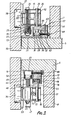
- the upper movement-enabling means 15 include support rollers 27 which are respectively supported by pins 26 passing through bearing plates 25 on both sides of the lower part of the front portion of a frame body 24, and horizontal rollers 30 (rotatable about a vertical axis) which each have a resilient annular member 29 surrounding the periphery thereof and are supported on vertical shafts 28 (Fig. 4) on both sides of the lower part of the rear portion of the frame body 24.
- the outer periphery of each of the vertical shafts 28, receives a bush 31 arranged to engage with the upper stop means 17.
- a support frame 32 is fitted for movement up and down, and, in the support frame 32, an internally- screw-threaded body 33 is mounted, with which a rotary screw shaft 34 extending vertically in the front portion of the frame body 24 is engaged.
- a vertical guide rod 35 extends through the rear portion of the frame body 24.
- a pair of links 36 is provided each pivotally mounted at one end thereof to the front portion of the support frame 32, and, to the other ends of the links 36, a mounting plate 37 is pivotally mounted in a recessed portion 38 thereof.
- each upper movement-enabling means 15 is fixed to the door section 10 by mounting screws 39, the recessed portion 38 thereof being formed in the door section 10, the support rollers 27 being supported on the horizontal guide portion 21 of the upper rail 13, and the horizontal rollers 30 being engaged in the vertical guide portion 22.
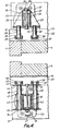
- the lower movement-enabling means 16 are each constructed as follows: In the front portion of a frame body 41, a movable frame 42 is provided for up and down movement.
- This movable frame 42 comprises guide rods 43 which are fitted into both side portions of the frame body 41 for movement up and down, connecting plates 44 and 45 which extend between the upper ends of the guide rods 43 and between the lower ends of the guide rods 43, an operating rod 46 which is coupled with the center portions of the upper and lower connecting plates 44 and 45, extending through the frame body 41, and a grip member 47 which is attached to a downwardly-projecting portion of the operating rod 46.
- helical springs 48 are mounted, respectively, so that the movable frame 42 is biased upwards.
- horizontal rollers 50 each having-a resilient annular body 49 disposed around the periphery thereof are supported on the upper end portion of the guide rods 43.
- a support frame 51 is mounted in the center portion of the frame body 41, and, to the front end portion of the support frame 51, the one ends of a pair of links 52 are pivoted, while, to the other ends a mounting plate 53 is pivoted in a recess 54 thereof.
- a shaft-like stop rod 55 is provided which acts as a locking body which is arranged to engage with the lower stop means 18.
- the mounting plate 53 is secured to the door section 10 by mounting screws 56 in the recess 54 which lies within in the door section 10, and the horizontal rollers 50 are engaged in the guide portion 24 of the lower rail 14.
- the upper stop means 17 includes an approximately inverted-L-shaped frame body 61 as best shown in Figs. 3 and 5, and, in the inner lower portion of the frame body 61, a support block 62 is mounted. At one side of the frame body 61, a support pin 63 is mounted extending between the support block 62 and the upper portion of the frame body 61, and, in the upper inside portion of the frame body 61, the base portion of a .stop member 64 is supported on the support pin 63 so as to be rotatable horizontally.
- the stop member 64 has a tapered guide portion 65 extending obliquely along the outer surface of the stop member 64 from its tip side, and further, a part-circular recess 66 is formed which continues to the guide portion 65. Between the frame body 61 and the leading end portion of the stop member 64, a helical spring 67 is so located that the stop member 64 is biased outwardly.
- the frame body 61 is fixed, together with the support block 62, to the rear side wall surface of the upper rail 13 by means of several screws 68, in which case the stop member 64 is located within the guide portion 22 so that the bush 31 of the outer one of the vertical shafts 28 of the upper movement-enabling means 15 which are movable along the guide portion 22 can be engaged in the recess 66 of the stop member 64.
- the lower stop means 18 has an approximately U-shaped frame body 7 1 as best shown in Figs. 3 and 6 and, in the upper inside portion of the frame body 71, a support block 72 is located.
- a recess 74 is formed continuing to a tapered guide portion 73 extending obliquely from the tip of the support block 72.
- a support pin 75 is mounted extending between the underside portion of the frame body 71 and the support block 72, so that the intermediate portion of a stop member 76 made of a synthetic resin is supported on the support pin 75 so as to allow the stop member 76 to be rotated horizontally.
- the stop member 76 has a tapered guide portion 77 extending obliquely from the tip thereof along the outer side surface thereof, and a part-circular recess 78 is formed continuing to this guide portion 77. Furthermore, between the outer leg portion of the frame body 71 and the base portion of the stop member 76, a helical spring 79 is provided, so that the tip of the stop member 76 is biased outwards.
- the frame body 71 is fixed, together with the support block 72, to the rear side wall surface of the lower rail 14 by means of screws 80, in which case the stop member 76 is located within the track portion along which the stop rod 55 of the lower movement-enabling means 16 is moved, so that the stop rod 55 can be brought into the recess 78 of the stop member 76.
- the pair of doors 10 are mounted on the body 2 as follows.
- the upper movement-enabling means 15 of the respective doors 10 are disposed on the upper rail 13 so that the support rollers 27 are brought into contact with the horizontal guide portion 21, while the horizontal rollers 30 are inserted into the vertical guide portion 22.
- the horizontal rollers 50 of the lower movement-enabling means 16 are pulled down, together with the movable frame 42, by the grip member 47 of the movable frame 42 on the lower movement-enabling means 16, and, in this state, the horizontal rollers 50 are positioned below the guide portion 23 of the lower rail 14; and then, the movable frame 42 pulled downwardly is released so that the horizontal rollers 50 are allowed to return upwardly together with the movable frame 42 by the force of the springs 48, so that the horizontal rollers 50 are inserted into the guide portion 23.
- each upper movement-enabling means 15 When mounting the pair of doors 10, the screwed shaft 34 of each upper movement-enabling means 15 is rotated so that, through the internally screw-threaded body 33, the support frame 32 is moved up or down, the height or vertical location of the doors 10 being thus adjusted.
- each upper movement-enabling means 15 When the doors 10 are maintained in their closed state, the bush 31 of the outer vertical shaft 28 of each upper movement-enabling means 15 is engaged in the recess 66 of the upper stop member 64 and held there by the force of the spring 67, while at the same time, the stop rod 55 of each lower movement-enabling means 16 is engaged in the recess 78 of the lower stop body 76 and held there by the force of the spring 79, so that the upper and lower movement-enabling means 15 and 16 in the respective end portions of the doors 10 are fixed in position, so that the doors are maintained in their closed state.
- the movement-enabling means 15 and 16 of the door 10 on the other side are moved, whereby, in the upper part of the door section 10, the bush 31 of the outer vertical shaft 28 which has so far been retained in the recess 66 of the stop member 64 disengages thus turning the stop member 64 against the force of the spring 67, while at the same time, the stop rod 55 which has so far been retained in the depression 78 of the stop member 76 disengages therefrom, turning the stop member 76 against the force of the spring 79. In this way, the movement-enabling means 15 and 16 of the door on said side are released from the fixed or retained state and moved.
- the upper and lower movement-enabling means 15 and 16 of the other door 10 are subject to a force when the door opening operation is started, but since the movement-enabling means 15 and 16 are located at the side opposite to the side where the door sections are to be opened, the means 15 and 16 substantially ceases to be subject to this force, the instant the door sections 10 are opened, and thus maintained in a fixed state by the stops 64 and 76 which are biased by the springs 67 and 79, respectively.
- the upper and lower stop means 17 and 18 are provided for cooperation with the upper and lower movement-enabling means 15 and 16, respectively, it is alternatively possible to provide stop means only for the upper or only for the lower movement-enabling means 15;16.
- the stop means may be of any type which can retain the movement-enabling means under bias forces which produce the same effect as has been hereinbefore described, and therefore, the stop means may also be constructed such that liminar springs for biasing the movement-enabling means are mounted on the inner sides of the rails or ball bearings provided on the movement-enabling means so as to be resiliently extended therefrom and are fitted into recesses provided in the rails.
- the main body is box-shaped, but the present invention can also be applied to, for example, a closet formed such that doors are mounted on the open front portion of a main body comprising a recess made in a wall of a building, in which case, however, the upper and lower rails 13 and 14 are disposed on the support frame fixed in the recessed wall portion, instead of the top plate 5 and the bottom plate 6.
- the main body is closed by a pair of door sections
- the present invention can also be applied to a particularly wide container in which two or more pairs of such door sections are mounted side-by-side.
- the door sections can be freely moved to the right and to the left, and therefore, the arrangement is particularly suitable for items of substantial length from side to side to be deposited and removed.
- such two or more pairs of doors can also be pivotally coupled together by means of hinges.
- the folding door assembly according to the present invention can thus consist of more than two pairs of door sections.
- Both vertical edges of a pair of doors are retained by stop means, and therefore, by pulling on one of the paired door sections held in a retained state in one or the other direction, the paired door sections are moved in that direction so as to fold up, under pivotal movement, with the hinged inner vertical edge portions thereof extending outwardly.
- the paired door sections can be opened in either direction, and, by pulling the other door section in the closing direction, the door sections are unfolded, under pivotal movement, with the hinged inner vertical edge portions thereof progressively flattened towards the opening plane of the container and thus, they can be closed smoothly and infallibly.
Landscapes
- Engineering & Computer Science (AREA)
- Mechanical Engineering (AREA)
- Support Devices For Sliding Doors (AREA)
- Extensible Doors And Revolving Doors (AREA)
Applications Claiming Priority (2)
| Application Number | Priority Date | Filing Date | Title |
|---|---|---|---|
| JP60159667A JPS6219112A (ja) | 1985-07-19 | 1985-07-19 | 収納装置 |
| JP159667/85 | 1985-07-19 |
Publications (3)
| Publication Number | Publication Date |
|---|---|
| EP0209386A2 true EP0209386A2 (de) | 1987-01-21 |
| EP0209386A3 EP0209386A3 (en) | 1987-04-22 |
| EP0209386B1 EP0209386B1 (de) | 1990-11-07 |
Family
ID=15698705
Family Applications (1)
| Application Number | Title | Priority Date | Filing Date |
|---|---|---|---|
| EP86305500A Expired EP0209386B1 (de) | 1985-07-19 | 1986-07-16 | Kleiderschrank oder andere Container mit Falttüren |
Country Status (5)
| Country | Link |
|---|---|
| US (1) | US4729615A (de) |
| EP (1) | EP0209386B1 (de) |
| JP (1) | JPS6219112A (de) |
| CA (1) | CA1275300C (de) |
| DE (1) | DE3675449D1 (de) |
Cited By (1)
| Publication number | Priority date | Publication date | Assignee | Title |
|---|---|---|---|---|
| EP0390997A2 (de) * | 1989-04-03 | 1990-10-10 | Kabushiki Kaisha Murakoshi Seiko | Falttürapparat |
Families Citing this family (8)
| Publication number | Priority date | Publication date | Assignee | Title |
|---|---|---|---|---|
| JPS63186872U (de) * | 1987-05-25 | 1988-11-30 | ||
| CA2032210C (en) * | 1989-12-26 | 1999-09-07 | Charles E. Williams | Multi-directional carrier system for operable partitions |
| US5568673A (en) * | 1994-10-27 | 1996-10-29 | Arthur Cox & Sons, Inc. | Pivot pin assembly for folding door |
| US6581242B2 (en) | 2001-03-01 | 2003-06-24 | Modernfold, Inc. | Track and trolley system for movable wall panels |
| KR100461528B1 (ko) * | 2001-12-03 | 2004-12-14 | 주식회사 새턴바스 | 수납장 문의 슬라이딩 로울러 구조 |
| IT1402815B1 (it) * | 2010-12-03 | 2013-09-27 | Borrtoluzzi Lab S R L | Dispositivo per l'applicazione di porte a scomparsa laterale, particolarmente per mobili |
| US20190323275A1 (en) * | 2018-01-25 | 2019-10-24 | Robert M. Stell | Folding barn style door and hardware |
| US10947762B2 (en) * | 2018-05-22 | 2021-03-16 | Monadnock Millwork, Llc | Articulating mounting bracket for hanging doors |
Citations (5)
| Publication number | Priority date | Publication date | Assignee | Title |
|---|---|---|---|---|
| US3102582A (en) * | 1957-11-25 | 1963-09-03 | Rudnick Jack | Folding door structure |
| DE2137144A1 (de) * | 1971-07-24 | 1973-02-01 | Edwin Kisling | Faltschrankbeschlag fuer stumpf aufliegende schranktueren |
| CH592232A5 (en) * | 1975-07-01 | 1977-10-14 | Stampfli J Ag | Folding and sliding doors hinge - is machined from solid profile and has bores with self lubricated sleeves |
| DE3327674A1 (de) * | 1983-07-30 | 1985-02-07 | Hans 4520 Melle Huntebrinker | Kueche |
| EP0152533A1 (de) * | 1984-02-18 | 1985-08-28 | INDUSTRIEBAU BÖNNIGHEIM GmbH + Co. | Falttür deren Türblätter verwindungssteif ausgebildet sind |
Family Cites Families (3)
| Publication number | Priority date | Publication date | Assignee | Title |
|---|---|---|---|---|
| US746758A (en) * | 1903-01-15 | 1903-12-15 | James H Stiggleman | Cabinet |
| US3221804A (en) * | 1963-02-18 | 1965-12-07 | Rudnick Jack | Folding door structure and assembly |
| US3403954A (en) * | 1967-01-18 | 1968-10-01 | A & A Sheet Metal Products | Safety storage cabinet |
-
1985
- 1985-07-19 JP JP60159667A patent/JPS6219112A/ja active Granted
-
1986
- 1986-07-16 DE DE8686305500T patent/DE3675449D1/de not_active Expired - Fee Related
- 1986-07-16 EP EP86305500A patent/EP0209386B1/de not_active Expired
- 1986-07-17 US US06/886,354 patent/US4729615A/en not_active Expired - Fee Related
- 1986-07-18 CA CA000514173A patent/CA1275300C/en not_active Expired
Patent Citations (5)
| Publication number | Priority date | Publication date | Assignee | Title |
|---|---|---|---|---|
| US3102582A (en) * | 1957-11-25 | 1963-09-03 | Rudnick Jack | Folding door structure |
| DE2137144A1 (de) * | 1971-07-24 | 1973-02-01 | Edwin Kisling | Faltschrankbeschlag fuer stumpf aufliegende schranktueren |
| CH592232A5 (en) * | 1975-07-01 | 1977-10-14 | Stampfli J Ag | Folding and sliding doors hinge - is machined from solid profile and has bores with self lubricated sleeves |
| DE3327674A1 (de) * | 1983-07-30 | 1985-02-07 | Hans 4520 Melle Huntebrinker | Kueche |
| EP0152533A1 (de) * | 1984-02-18 | 1985-08-28 | INDUSTRIEBAU BÖNNIGHEIM GmbH + Co. | Falttür deren Türblätter verwindungssteif ausgebildet sind |
Cited By (2)
| Publication number | Priority date | Publication date | Assignee | Title |
|---|---|---|---|---|
| EP0390997A2 (de) * | 1989-04-03 | 1990-10-10 | Kabushiki Kaisha Murakoshi Seiko | Falttürapparat |
| EP0390997A3 (de) * | 1989-04-03 | 1991-10-16 | Kabushiki Kaisha Murakoshi Seiko | Falttürapparat |
Also Published As
| Publication number | Publication date |
|---|---|
| JPH0262243B2 (de) | 1990-12-25 |
| JPS6219112A (ja) | 1987-01-27 |
| EP0209386B1 (de) | 1990-11-07 |
| DE3675449D1 (de) | 1990-12-13 |
| US4729615A (en) | 1988-03-08 |
| EP0209386A3 (en) | 1987-04-22 |
| CA1275300C (en) | 1990-10-16 |
Similar Documents
| Publication | Publication Date | Title |
|---|---|---|
| US6292981B1 (en) | Crescent hinge | |
| US4729615A (en) | Wardrobe or other container with folding doors | |
| EP0390997B1 (de) | Falttürapparat | |
| US5938306A (en) | Cabinet and door assembly | |
| EP0200542B1 (de) | Aufhängungsvorrichtung für Schranktüren | |
| US6634727B2 (en) | Closet doors with integrated shelves | |
| US3390418A (en) | Lightweight door and mounting structure therefor | |
| US3102582A (en) | Folding door structure | |
| JPH11336413A (ja) | 半自動式回転スライドドア | |
| KR102634414B1 (ko) | 가구용 슬라이딩 도어 시스템 | |
| JPH078760Y2 (ja) | 間仕切り装置 | |
| JPH04131485A (ja) | 扉装置 | |
| JP2002021435A (ja) | 折戸用ローラー装置及びこの折戸用ローラー装置を備えた家具及びクローゼット | |
| JPH0637480U (ja) | 収納ボックス | |
| JPS6133807Y2 (de) | ||
| US886531A (en) | Sliding-door fixture. | |
| KR940003961Y1 (ko) | 서랍의 가이드 레일 | |
| JPS6337427Y2 (de) | ||
| JPS5926754B2 (ja) | 折畳扉用開閉装置 | |
| JPS603247Y2 (ja) | 折り畳み扉 | |
| JP2573800Y2 (ja) | 間仕切り装置の下レールの構造 | |
| JPH0635102Y2 (ja) | 天袋付間仕切り | |
| JPH07255539A (ja) | ライティングビューロー | |
| JPS6347259Y2 (de) | ||
| JPH079129B2 (ja) | 折り畳み扉を有する収納家具 |
Legal Events
| Date | Code | Title | Description |
|---|---|---|---|
| PUAI | Public reference made under article 153(3) epc to a published international application that has entered the european phase |
Free format text: ORIGINAL CODE: 0009012 |
|
| AK | Designated contracting states |
Kind code of ref document: A2 Designated state(s): DE FR GB IT |
|
| PUAL | Search report despatched |
Free format text: ORIGINAL CODE: 0009013 |
|
| AK | Designated contracting states |
Kind code of ref document: A3 Designated state(s): DE FR GB IT |
|
| 17P | Request for examination filed |
Effective date: 19870928 |
|
| 17Q | First examination report despatched |
Effective date: 19890209 |
|
| ITF | It: translation for a ep patent filed |
Owner name: UFFICIO TECNICO ING. A. MANNUCCI |
|
| GRAA | (expected) grant |
Free format text: ORIGINAL CODE: 0009210 |
|
| AK | Designated contracting states |
Kind code of ref document: B1 Designated state(s): DE FR GB IT |
|
| REF | Corresponds to: |
Ref document number: 3675449 Country of ref document: DE Date of ref document: 19901213 |
|
| ET | Fr: translation filed | ||
| PGFP | Annual fee paid to national office [announced via postgrant information from national office to epo] |
Ref country code: GB Payment date: 19910705 Year of fee payment: 6 |
|
| PGFP | Annual fee paid to national office [announced via postgrant information from national office to epo] |
Ref country code: FR Payment date: 19910721 Year of fee payment: 6 |
|
| ITTA | It: last paid annual fee | ||
| PGFP | Annual fee paid to national office [announced via postgrant information from national office to epo] |
Ref country code: DE Payment date: 19910830 Year of fee payment: 6 |
|
| PLBE | No opposition filed within time limit |
Free format text: ORIGINAL CODE: 0009261 |
|
| STAA | Information on the status of an ep patent application or granted ep patent |
Free format text: STATUS: NO OPPOSITION FILED WITHIN TIME LIMIT |
|
| 26N | No opposition filed | ||
| PG25 | Lapsed in a contracting state [announced via postgrant information from national office to epo] |
Ref country code: GB Effective date: 19920716 |
|
| GBPC | Gb: european patent ceased through non-payment of renewal fee |
Effective date: 19920716 |
|
| PG25 | Lapsed in a contracting state [announced via postgrant information from national office to epo] |
Ref country code: FR Effective date: 19930331 |
|
| PG25 | Lapsed in a contracting state [announced via postgrant information from national office to epo] |
Ref country code: DE Effective date: 19930401 |
|
| REG | Reference to a national code |
Ref country code: FR Ref legal event code: ST |
|
| PG25 | Lapsed in a contracting state [announced via postgrant information from national office to epo] |
Ref country code: IT Free format text: LAPSE BECAUSE OF NON-PAYMENT OF DUE FEES;WARNING: LAPSES OF ITALIAN PATENTS WITH EFFECTIVE DATE BEFORE 2007 MAY HAVE OCCURRED AT ANY TIME BEFORE 2007. THE CORRECT EFFECTIVE DATE MAY BE DIFFERENT FROM THE ONE RECORDED. Effective date: 20050716 |