EP0208355B1 - Verfahren zum Vergrössern/Verkleinern von Halbtonbildern - Google Patents
Verfahren zum Vergrössern/Verkleinern von Halbtonbildern Download PDFInfo
- Publication number
- EP0208355B1 EP0208355B1 EP86201008A EP86201008A EP0208355B1 EP 0208355 B1 EP0208355 B1 EP 0208355B1 EP 86201008 A EP86201008 A EP 86201008A EP 86201008 A EP86201008 A EP 86201008A EP 0208355 B1 EP0208355 B1 EP 0208355B1
- Authority
- EP
- European Patent Office
- Prior art keywords
- area
- gray level
- pixels
- pattern
- series
- Prior art date
- Legal status (The legal status is an assumption and is not a legal conclusion. Google has not performed a legal analysis and makes no representation as to the accuracy of the status listed.)
- Expired - Lifetime
Links
- 238000000034 method Methods 0.000 title claims abstract description 51
- 239000011159 matrix material Substances 0.000 claims abstract description 79
- 230000009466 transformation Effects 0.000 claims abstract description 7
- 230000001174 ascending effect Effects 0.000 claims description 9
- 239000000306 component Substances 0.000 description 25
- 230000009467 reduction Effects 0.000 description 24
- 238000006722 reduction reaction Methods 0.000 description 24
- 239000013598 vector Substances 0.000 description 21
- 238000012545 processing Methods 0.000 description 6
- 230000005540 biological transmission Effects 0.000 description 4
- 238000006243 chemical reaction Methods 0.000 description 4
- 238000010586 diagram Methods 0.000 description 3
- 230000000694 effects Effects 0.000 description 2
- 230000001360 synchronised effect Effects 0.000 description 2
- 230000015572 biosynthetic process Effects 0.000 description 1
- 238000004364 calculation method Methods 0.000 description 1
- 230000007423 decrease Effects 0.000 description 1
- 230000006735 deficit Effects 0.000 description 1
- 238000003384 imaging method Methods 0.000 description 1
- 230000001771 impaired effect Effects 0.000 description 1
Images


Classifications
-
- H—ELECTRICITY
- H04—ELECTRIC COMMUNICATION TECHNIQUE
- H04N—PICTORIAL COMMUNICATION, e.g. TELEVISION
- H04N1/00—Scanning, transmission or reproduction of documents or the like, e.g. facsimile transmission; Details thereof
- H04N1/40—Picture signal circuits
- H04N1/40068—Modification of image resolution, i.e. determining the values of picture elements at new relative positions
-
- H—ELECTRICITY
- H04—ELECTRIC COMMUNICATION TECHNIQUE
- H04N—PICTORIAL COMMUNICATION, e.g. TELEVISION
- H04N1/00—Scanning, transmission or reproduction of documents or the like, e.g. facsimile transmission; Details thereof
- H04N1/40—Picture signal circuits
- H04N1/40075—Descreening, i.e. converting a halftone signal into a corresponding continuous-tone signal; Rescreening, i.e. combined descreening and halftoning
Definitions
- This invention relates to a method of enlarging/reducing a dithered image obtained from a rastered gray level image by means of a dither matrix.
- the associated raster dot is allocated a logic "1" while if the gray level is lower than the threshold the associated raster dot is allocated a logic "0".
- the analog image information is converted to a raster of two-level pixels or picture elements by means of which, for example, it is possible to control a printer to display the image, or by means of which the image information can be transmitted over transmission lines, e.g. in facsimile applications.
- Enlargement or reduction of the image by a given factor may also be required by a user.
- a method of reducing/enlarging an image is described, for example, in US Patent US-A-4,394,693.
- a number of rows and columns are simply omitted depending upon the required reduction factor.
- b-a lines/columns are omitted from each group of b lines/columns of the input image in order to give the required output image.
- the number of lines/columns (b-a) to be omitted is distributed as uniformly as possible over the group b lines/columns.
- c-b lines/columns are added to each group of b lines/columns of the input image.
- the number of lines/columns (c-b) to be added is distributed as uniformly as possible over the group of b lines/columns.
- Each of the added lines/columns has the same pixel pattern as one of the neighbouring lines/columns.
- This method can give acceptable results in the case of pure black/white images, such as drawings, but a number of problems arise if the method is used in connection with dithered images containing several gray levels, e.g. photographs and the like.
- Moiré distortion occurs due to the more or less uniform structure in which the pixels are removed from the pixel raster in the case of reduction or with which lines/columns are added to the raster in the case of enlargement.
- the uniform structure with which the pixels are omitted or added interferes with the uniform structure present in the dithered photographs as a result of the dithering method.
- Moiré distortion does not occur in the reduction of an image in those cases in which the omission pattern is in synchronism with the dither matrix used. This situation, however, will occur only in a very restricted number of cases, e.g. when an 8 ⁇ 8 dither matrix is used and a reduction from 4 to 3. In that case, however, there is another important disadvantage, because those pixels corresponding to one and the same part of the dither matrix are consistently omitted. These omitted pixels represent a number of specific gray level thresholds and by omitting all the pixels associated with these specific gray level thresholds the number of gray levels in the reduced image is greatly reduced. In the above example of an 8 ⁇ 8 dither matrix and a reduction from 4 to 3 the number of gray levels decreases from 65 to 37 or from 33 to 19 respectively (if each threshold occurs twice in the 8 ⁇ 8 matrix).
- the display means is capable of printing or displaying each pixel with high accuracy and high fineness, this image noise becomes very perceptible. Reducing or eliminating Moiré patterns by omitting/adding the pixels in accordance with an arbitrary scheme is then replaced by a sharp increase of the noise in the image without there being any real quality improvement.
- Another disadvantage of the known method is the fact that it is not possible to use excessively large reduction factors because with large reduction factors a relatively large number of pixels have to be omitted, and hence a relatively large part of the information content of the image.
- the object of the invention is to provide a method by means of which a dithered image can be reduced or enlarged while using a wide range of conversion factors, in such a manner that the information content of the original image remains unaffected or substantially unaffected, the occurrence of Moiré distortion is avoided and the signal/noise ratio of the image is affected insignificantly, if at all.
- the invention provides a method of enlarging/reducing a dithered image obtained from a rastered gray level image by means of a dither matrix, characterised by the following steps:
- the invention is based on the realization that conversion algorithms should not act directly on individual pixels, but must act on the pattern of the pixels or on the gray level of an area itself without affecting the pattern of the area.
- the entire image is divided up into a number of contiguous relatively small input areas and it is assumed that locally the intensity variation will be small within these input areas.
- the pattern in each area is divided into a pattern corresponding to an average gray level and a number of pixels deviating therefrom, which together form the high-frequency component of the area. Since, in the case of enlargement or reduction of an image, the gray level of each of the input areas will not change, this gray level can be transferred directly to the output area.
- the high-frequency pixels are then imaged on the associated output area by a linear co-ordinate transformation.
- the number of gray levels of the second dither matrix used in step d) is selected to be equal to the number of gray levels of the first dither matrix.
- step c) each of the deviating pixels is allocated an amplitude level equal to the difference between the threshold associated with the pixel from the first dither matrix and the average gray level, and only those deviating pixels whose amplitude is greater than a predetermined threshold are imaged on the corresponding output area.
- a threshold By the introduction of a threshold, only those deviating pixels of the input area which differ adequately from the average gray level of the associated input area are imaged on the corresponding output area. It has been found in practice that a correct choice of this threshold makes the signal/noise ratio of the reduced/enlarged image substantially equal to that of the original image.
- each threshold in the dither matrix is involved an equal number of times in the determination.
- an embodiment of the method according to the invention is characterised in that if the dimensions of the first dither matrix are not equal to the dimensions of the input areas in step b), use is made each time of an auxiliary matrix, which is to be determined separately for each input area, and which is found by placing a contiguous array of first dither matrices on the contiguous array of input areas, the thresholds of the dither matrices which fall within each area together forming the auxiliary matrix for that area.
- each output area will not be equal to a whole multiple of the dimensions of the dither matrix used, certainly not if the first dither matrix is also used for the output areas.
- One embodiment of the method according to the invention is characterised in that to perform step b) an estimated gray level is first determined by counting the number of pixels having the value 1 in the input area, and the standard pattern having the same number of 1-levels is selected as estimated gray level pattern, whereafter iterative comparison of this estimated gray level pattern with the neighbouring standard pattern (which have a 1-level more or less each time) is applied to determine that pattern at which the number of deviating pixels is minimal, which pattern is selected as the average gray level pattern.
- Fig. 1 represents an 8 ⁇ 8 dither matrix in which each gray level threshold 1-32 occurs twice in the total. If a gray level image converted to a raster of two-level pixels with this dither matrix is to be reduced, for example, by a factor 3/4, this means that in the known method one line/column has to be omitted each time after each three lines/columns. The lines/columns to be omitted are shown framed in the Figure. It will be apparent from the Figure that with this conversion factor 3/4 all the pixels associated with the gray level thresholds 31, 28 ... (fourth column), 2, 6 ... (eighth column), 29, 24, ... (fourth row) and 3, 9, ... (eighth row) disappear from the complete picture. This means that the number of gray levels in the reduced image has been reduced from 32+1 to 18+1. Although Moiré distortion does not occur in this case, the picture quality is considerably impaired by the considerable reduction of the number of gray levels.
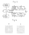
- Fig. 3 diagrammatically represents the method used according to the invention.
- the dithered image information 1 is split, by means of the same dither matrix 3 as was used for dithering the original image, into a series of average gray levels and an associated series of high-frequency components.
- Each of the elements from the two series is then subjected to an enlargement/reduction processing in the respective blocks 4 and 5 and then again dithered in the respective blocks 6 and 7.
- the blocks 4 and 6, or 5 and 7 respectively can also be combined as shown in dotted lines in the Figure, depending on the operations applied, which will be discussed in detail hereinafter.
- the associated components of the two series are then re-combined at junction point 8 to give the reduced/enlarged dithered image.
- each sub-area will have a specific average gray level and there will also occur in each sub-area deviations from this average gray level, hereinafter referred to as the high-frequency component, which deviations, however, will not be excessive in accordance with the above assumption.
- each input area is imaged on an output area of a ⁇ a pixels, the enlargement/reduction ratio being equal to a/b. If the information from each input area is now divided up in the above manner into an average gray level and a high-frequency component deviating from this gray level, it will be apparent that the gray level does not change when an input area is imaged on an output area. For imaging this average gray level on the output area, therefore, the output area must be filled with a pattern of pixels corresponding to this same average gray level.
- the second dither matrix is equal to the first dither matrix.
- the average gray level of an input area can be determined (in block 2 in Fig. 3) by comparing the pixel pattern of the input area (originating from block 1 in Fig. 3) with a series of standard patterns.
- These standard patterns arise by dithering, with the dither matrix (originating from block 3 in Fig. 3), a number of image areas each filled with a unique gray level from the series of possible different gray levels.
- Fig. 4 represents two of such standard patterns dithered with the matrix represented in Fig. 1.
- Fig. 4a represents the standard pattern obtained when dithering a uniform area with a gray level above the threshold 7 but below the threshold 8
- Fig. 4b represents a standard pattern obtained when dithering a uniform area with a gray level above the threshold 23 but below the threshold 24.
- a series of 32 standard patterns is associated with the dither matrix represented in Fig. 1.
- a series of n2 standard patterns is associated with an n ⁇ n dither matrix in which each threshold occurs only once.
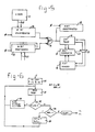
- Fig. 5 represents a circuit provided with a memory 11 of the EPROM type. All possible standard patterns are beforehand stored in this memory in an ascending gray level sequence. These standard patterns need only be determined once for the dither matrix used.
- the circuit of Fig. 5 is also provided with two shift registers 12 and 13. The pixel pattern of an input area is fed to the shift register 13 at the beginning of a comparison procedure via the 64-bit line 22. The shift register 13 is in a feedback circuit. A next standard pattern is fed from the memory 11 to the shift register 12 after every 64 shift pulses.
- the outputs of the last stages of the shift registers 12 and 13 are connected to the inputs of an exclusive OR gate 14, the output of which is connected on the one hand to the 5-bit counter 16 and, on the other hand, to the 64-bit shift register 15.
- an exclusive OR gate 14 By the synchronous feed of shift pulses to both shift registers 12 and 13 the pixel pattern of an input area in register 13 is compared each time with a standard pattern in the register 12. A 1 is delivered at the output of gate 14 if no equality is found between the two patterns for a specific picture point. In that case the 5-bit counter is raised one step.
- the shift clock pulses ⁇ are also fed to the 64-bit shift register 15, in which, therefore, the deviating pixels are stored for each standard pattern.
- the 5-bit comparator 17 determines whether the value accumulated in the counter 16 is less than the value in a 5-bit register 18 which at the start of the comparison procedure was filled with all 1 ⁇ s. If the contents of the counter 16 are less than those of the register 18, gate 19 is opened and the contents of the counter 16 are written in the register 18 instead of the value previously present therein. Comparison with the next standard pattern then starts.
- the comparison procedure can be stopped as soon as the value accummulated at any time in the counter 16 starts to rise again, in other words as soon as the comparator 17 determines that the value in the counter 16 is greater than the value in the register 18.
- the standard pattern corresponding to the average gray level of the input area is situated in the shift register 12 and the high-frequency component, i.e. the pattern of those pixels which deviate from the average gray level, is situated in the register 15.
- y the pixel pattern of the input area
- b the pixel pattern of the average gray level component
- h the pixel pattern of the hf component.
- the Hamming distance is in actual fact determined between b and y .
- the Hamming distance can be regarded as the number of positions in which b and y differ from one another.
- Each of the possible vectors b can be allocated a unique weight directly associated with the associated gray level. If the gray level is equal to i, the number of 1 ⁇ s in the associated vector b i is equal to 2i (if the dither matrix of Fig. 1 is used. In dither matrices in which each threshold occurs only once, the number of ones is equal to i).
- the vectors b i can be ordered in ascending sequence by reference to this weight (this order has in fact already been used in Fig. 5 in storing the standard patterns in the memory 11).
- Fig. 6 represents, in the form of a flow diagram this time, how this modified comparison procedure can be performed.
- the pixel pattern of the input area or the vector y is introduced in block 30, in which the number of ones in this pattern is counted, to give an estimated average gray level c, whereafter on the basis of this number of ones c i and b i are allocated an associated value.
- the Hamming distance d( y , b i ) is then determined in block 31 for this specific gray level vector b i .
- Block 32 checks whether the determined Hamming distance is less than a variable d which is initiallly set to a value above the number of thresholds, e.g. 100.
- Ever-smaller values of d are sought in the one direction by reducing i.
- block 34 checks whether the step variable incr is positive or negative. This step variable was initially made negative and in the first instance the block 34 wil accordingly give the answer "yes", resulting in making the variable incr in block 35 positive and increasing the value c. Block 31 is then returned to again and the smallest Hamming distance is again sought with increasing values of i.
- each vector y and b is written as a series of ones and zeroes ordered in ascending sequence of the associated thresholds.
- Fig. 7a represents a simplified 4 ⁇ 4 dither matrix with 16 gray level thresholds.
- Fig. 7b represents as an example the standard pattern for the threshold 5, i.e. a 1 is allocated to all the thresholds ⁇ 5 and an 0 is allocated to all the thresholds >5. If this pattern is written as a series of ones and zeroes in ascending threshold sequence, the result is a series with a number of ones at the beginning until the threshold associated with this standard pattern is reached and then the series is continued with a number of zeroes as indicated below.
- the sum d1(i)+d u (i) has a minimum between the thresholds 5 and 6, and this means that the average gray level in the pattern under examination has the threshold 5.
- This gray level determination can be performed in the same way if there is a high-frequency component in the pattern, i.e. if one or more pixels in the pattern deviate from the standard pattern.
- Fig. 7c represents a pattern deviating in this way, in which the pixel associated with the threshold 2 is not equal to 1 as in the standard pattern but is equal to 0, and in which the pixel associated with the threshold 11 is not equal to 0 as in the standard pattern but is equal to 1.
- the performance of the minimum determination for the pattern of Fig. 7c is as follows:
- the average gray level component has been found by means of one of the methods described in the foregoing, it is a simple matter, using an exclusive OR processing, to trace all those pixels which deviate from the standard pattern corresponding to this average gray level. For the example of Fig. 7 this would mean that the high-frequency component contains only a 1 at the positions of the thresholds 2 and 11 and otherwise contains only zeroes.
- the second dither matrix in the blocks 6 and 7 of Fig. 3 equal (at least insofar as concerns the number of gray levels) to the first dither matrix (in block 3 of Fig. 3). In that case, however, the dither matrix will generally no longer fit correctly on each output area. To be able to convert uniform gray areas faultlessly care must be taken to ensure that both the input areas and the output areas are well synchronized with the dither matrix to be used. Fig. 8 indicates how this synchronization can be obtained.
- the solid lines in Fig. 8 indicate an array of input areas A11, A12, ... A21, A22, ... etc. Each of these input areas has the same dimensions as the dither matrix used, in this example the dither matrix represented in Fig. 7a. This dither matrix is filled in in each of the areas A11 ...
- the Figure also represents in dotted lines the output areas B11, B12, ... B21, B22, ... etc, on which the input areas with the same indices must be respectively projected. It will be clear from this Figure that with the dimensions selected a reduction by a factor of 3/4 is aimed at.
- This technique can otherwise also be used if the dimensions of the input areas do not correspond to the dimensions of the first dither matrix. In that case too the gray level structure in the input areas is maintained by determining an auxiliary matrix for each input area in the manner described above.
- auxiliary matrices can be similarly used in the enlargement of images, such auxiliary matrices also being found by placing a contiguous array of dither matrices on the contiguous array of output areas and each time forming an auxiliary matrix for a specific output area from the thresholds of the array of dither matrices which fall within the area in question.
- the high-frequency component of the input area can be imaged on the output area by linear co-ordinate transformation.
- the co-ordinates ⁇ 0, y0 of an input area A ij of b ⁇ b pixels are imaged on the co-ordinates ⁇ c , y c of the output area B ij of a ⁇ a pixels by the following simple linear co-ordinate transformation: It should be noted here that each input and output area A ij and B ij respectively has its own system of co-ordinates. For the above formulae, the left-hand top corner of each area is selected as the co-ordinate origin in each case.
- the high-frequency pixels are now written in in the output area instead of the pixels associated with the average gray level pattern originally written in there as the result of the processing in block 6 of Fig. 3.
- the high-frequency pixels have a special information content and hence a higher priority and are all transferred to the output area in a one-to-one transformation from the input area so that practically nothing, if anything, is lost from the information content of the original image.
- a high-frequency pixel from an input area is for example imaged on a group of four contiguous high-frequency pixels in the corresponding output area.
- a threshold is preferably introduced to include in the high-frequency component only those pixels which deviate from the average gray pattern in a predetermined manner. It has been found that if a correctly selected threshold difference is introduced the signal/noise ratio of the processed image (enlarged or reduced) is approximately equal to that of the original image. If, for example, the average gray level lies between the thresholds 6 and 7, and hence the standard pattern selected in block 4 of Fig.
- both the average gray level component and the high-frequency component are again available in dithered form in suitable manner in accordance with the foregoing, at the outputs of the blocks 6 and 7 in Fig. 3, both components are superimposed in block 8 by the fact that at those positions where a high-frequency pixel is present this pixel occurs instead of the corresponding pixel in the average gray level component.
- the enlarged or reduced image is delivered in dithered form at the output of the junction point 8.
Landscapes
- Engineering & Computer Science (AREA)
- Multimedia (AREA)
- Signal Processing (AREA)
- Image Processing (AREA)
- Editing Of Facsimile Originals (AREA)
- Preparing Plates And Mask In Photomechanical Process (AREA)
- Facsimile Image Signal Circuits (AREA)
Claims (13)
Priority Applications (1)
| Application Number | Priority Date | Filing Date | Title |
|---|---|---|---|
| AT86201008T ATE60178T1 (de) | 1985-06-27 | 1986-06-11 | Verfahren zum vergroessern/verkleinern von halbtonbildern. |
Applications Claiming Priority (2)
| Application Number | Priority Date | Filing Date | Title |
|---|---|---|---|
| NL8501845A NL8501845A (nl) | 1985-06-27 | 1985-06-27 | Werkwijze voor het vergroten/verkleinen van ditherbeelden. |
| NL8501845 | 1985-06-27 |
Publications (2)
| Publication Number | Publication Date |
|---|---|
| EP0208355A1 EP0208355A1 (de) | 1987-01-14 |
| EP0208355B1 true EP0208355B1 (de) | 1991-01-16 |
Family
ID=19846205
Family Applications (1)
| Application Number | Title | Priority Date | Filing Date |
|---|---|---|---|
| EP86201008A Expired - Lifetime EP0208355B1 (de) | 1985-06-27 | 1986-06-11 | Verfahren zum Vergrössern/Verkleinern von Halbtonbildern |
Country Status (6)
| Country | Link |
|---|---|
| US (1) | US4937677A (de) |
| EP (1) | EP0208355B1 (de) |
| JP (1) | JPH0693246B2 (de) |
| AT (1) | ATE60178T1 (de) |
| DE (1) | DE3676894D1 (de) |
| NL (1) | NL8501845A (de) |
Families Citing this family (16)
| Publication number | Priority date | Publication date | Assignee | Title |
|---|---|---|---|---|
| JPH0754547B2 (ja) * | 1985-11-15 | 1995-06-07 | コニカ株式会社 | 画像処理装置 |
| JPH0650522B2 (ja) * | 1988-09-22 | 1994-06-29 | インターナショナル・ビジネス・マシーンズ・コーポレーション | 表示システム |
| JPH02217897A (ja) * | 1989-02-20 | 1990-08-30 | Hitachi Ltd | 画素密度変換方式 |
| US5179640A (en) * | 1990-02-01 | 1993-01-12 | Oce Graphics Usa Inc. | Generating repeating patterns from a pattern header |
| JPH03284054A (ja) * | 1990-03-30 | 1991-12-13 | Seiko Instr Inc | 画素密度変換装置 |
| US5339171A (en) * | 1990-04-24 | 1994-08-16 | Ricoh Company, Ltd. | Image processing apparatus especially suitable for producing smooth-edged output multi-level tone data having fewer levels than input multi-level tone data |
| JP2788699B2 (ja) * | 1992-12-16 | 1998-08-20 | 松下電器産業株式会社 | 画像データ処理装置 |
| DE69433603D1 (de) * | 1993-10-26 | 2004-04-15 | Canon Kk | Bildverarbeitungsverfahren und -gerät |
| SG73959A1 (en) * | 1994-08-24 | 2000-07-18 | Seiko Epson Corp | Multiple tonal range image processing system |
| US5703695A (en) * | 1995-03-20 | 1997-12-30 | Nguyen; Hugh P. | Multi-dot dither matrix generation |
| US5638187A (en) * | 1996-02-23 | 1997-06-10 | Hewlett-Packard Company | Image dithering method enabling conversion of a gray level pixel image into a binary pixel image |
| US7245786B2 (en) * | 2002-05-10 | 2007-07-17 | 976076 Alberta Inc. | Filtering artifact from fMRI data using the stockwell transform |
| US7424166B2 (en) * | 2003-12-24 | 2008-09-09 | Sharp Laboratories Of America, Inc. | Enhancing the quality of decoded quantized images |
| US7424168B2 (en) * | 2003-12-24 | 2008-09-09 | Sharp Laboratories Of America, Inc. | Enhancing the quality of decoded quantized images |
| KR100766081B1 (ko) * | 2006-08-30 | 2007-10-12 | 삼성전자주식회사 | 영상신호처리장치 및 그의 영상신호처리방법 |
| US10832613B2 (en) | 2018-03-07 | 2020-11-10 | At&T Intellectual Property I, L.P. | Image format conversion using luminance-adaptive dithering |
Family Cites Families (9)
| Publication number | Priority date | Publication date | Assignee | Title |
|---|---|---|---|---|
| US4266249A (en) * | 1978-09-19 | 1981-05-05 | Bell Telephone Laboratories, Incorporated | Digital encoder for facsimile transmission |
| US4259694A (en) * | 1979-08-24 | 1981-03-31 | Xerox Corporation | Electronic rescreen technique for halftone pictures |
| JPS6049339A (ja) * | 1983-08-30 | 1985-03-18 | Dainippon Screen Mfg Co Ltd | 複製画像の編集装置 |
| US4758897A (en) * | 1985-04-30 | 1988-07-19 | Konishiroku Photo Industry Co., Ltd. | Method and apparatus for estimating halftone image from binary image |
| US4803558A (en) * | 1985-11-15 | 1989-02-07 | Konishiroku Photo Industry Co., Ltd. | Halftone image estimation methods for dither images |
| JP2794281B2 (ja) * | 1986-07-10 | 1998-09-03 | 株式会社日立製作所 | デイザ信号の符号復号処理装置 |
| US4730221A (en) * | 1986-10-16 | 1988-03-08 | Xerox Corporation | Screening techniques by identification of constant grey components |
| NL8602712A (nl) * | 1986-10-29 | 1988-05-16 | Oce Nederland Bv | Werkwijze voor het reconstrueren van een dithermatrix. |
| US4800443A (en) * | 1987-08-14 | 1989-01-24 | Tektronix, Inc. | Method and apparatus for carrying out a dithering operation |
-
1985
- 1985-06-27 NL NL8501845A patent/NL8501845A/nl not_active Application Discontinuation
-
1986
- 1986-06-11 DE DE8686201008T patent/DE3676894D1/de not_active Expired - Lifetime
- 1986-06-11 EP EP86201008A patent/EP0208355B1/de not_active Expired - Lifetime
- 1986-06-11 AT AT86201008T patent/ATE60178T1/de not_active IP Right Cessation
- 1986-06-24 JP JP61148016A patent/JPH0693246B2/ja not_active Expired - Fee Related
-
1989
- 1989-06-06 US US07/362,076 patent/US4937677A/en not_active Expired - Lifetime
Also Published As
| Publication number | Publication date |
|---|---|
| NL8501845A (nl) | 1987-01-16 |
| US4937677A (en) | 1990-06-26 |
| JPS6225388A (ja) | 1987-02-03 |
| EP0208355A1 (de) | 1987-01-14 |
| JPH0693246B2 (ja) | 1994-11-16 |
| DE3676894D1 (de) | 1991-02-21 |
| ATE60178T1 (de) | 1991-02-15 |
Similar Documents
| Publication | Publication Date | Title |
|---|---|---|
| EP0208355B1 (de) | Verfahren zum Vergrössern/Verkleinern von Halbtonbildern | |
| EP0199469B1 (de) | Verfahren zur Wertbestimmung an einer halb-tonen Schwellenmatrix | |
| US5289293A (en) | Pixel density conversion and processing | |
| EP0238034B1 (de) | Verfahren zur Umsetzung der Bildelementdichte für Grautonbilder | |
| EP0407213B1 (de) | Bildverarbeitungsgerät | |
| KR960014303B1 (ko) | 화상 처리 장치 | |
| EP0454495A1 (de) | Halbton-Bildverarbeitungssystem | |
| JP3749282B2 (ja) | 画像処理装置 | |
| JP2000270208A (ja) | 画像処理装置及び画像処理方法 | |
| JP3539552B2 (ja) | 画像処理装置 | |
| US5825509A (en) | Image processing device with error-diffusion quantization function | |
| KR100440944B1 (ko) | 이진화상의 해상도를 축소시키는 방법 및 장치 | |
| JP3783815B2 (ja) | 画像処理装置 | |
| JPS58136173A (ja) | デイザ処理装置 | |
| JP2941288B2 (ja) | 画像処理システム | |
| JPH1188693A (ja) | 疑似階調処理装置 | |
| JP2608404B2 (ja) | 画像処理装置 | |
| JPH01212073A (ja) | 画像データ縮小処理装置 | |
| JPH06348834A (ja) | 画像処理装置 | |
| JPH0548881A (ja) | 画像変倍処理方式及び装置 | |
| US5943439A (en) | Method and apparatus for generating an image areas using halftone processing, binary contouring, and dithering conversion techniques | |
| JP2836992B2 (ja) | 画像変倍処理装置 | |
| JPH05176168A (ja) | 適応中間調処理方式 | |
| KR930005131B1 (ko) | 히스토그램 평활화법을 이용한 중간조 화상 추출 방법 | |
| JPH07123246A (ja) | 二値画像縮小装置 |
Legal Events
| Date | Code | Title | Description |
|---|---|---|---|
| PUAI | Public reference made under article 153(3) epc to a published international application that has entered the european phase |
Free format text: ORIGINAL CODE: 0009012 |
|
| AK | Designated contracting states |
Kind code of ref document: A1 Designated state(s): AT BE CH DE FR GB IT LI NL SE |
|
| 17P | Request for examination filed |
Effective date: 19870613 |
|
| 17Q | First examination report despatched |
Effective date: 19890615 |
|
| GRAA | (expected) grant |
Free format text: ORIGINAL CODE: 0009210 |
|
| AK | Designated contracting states |
Kind code of ref document: B1 Designated state(s): AT BE CH DE FR GB IT LI NL SE |
|
| REF | Corresponds to: |
Ref document number: 60178 Country of ref document: AT Date of ref document: 19910215 Kind code of ref document: T |
|
| REF | Corresponds to: |
Ref document number: 3676894 Country of ref document: DE Date of ref document: 19910221 |
|
| ITF | It: translation for a ep patent filed | ||
| ET | Fr: translation filed | ||
| K2C2 | Correction of patent specification (partial reprint) published |
Effective date: 19910116 |
|
| PLBE | No opposition filed within time limit |
Free format text: ORIGINAL CODE: 0009261 |
|
| STAA | Information on the status of an ep patent application or granted ep patent |
Free format text: STATUS: NO OPPOSITION FILED WITHIN TIME LIMIT |
|
| 26N | No opposition filed | ||
| EAL | Se: european patent in force in sweden |
Ref document number: 86201008.9 |
|
| NLT1 | Nl: modifications of names registered in virtue of documents presented to the patent office pursuant to art. 16 a, paragraph 1 |
Owner name: OCE-TECHNOLOGIES B.V. |
|
| PGFP | Annual fee paid to national office [announced via postgrant information from national office to epo] |
Ref country code: AT Payment date: 19990512 Year of fee payment: 14 |
|
| PGFP | Annual fee paid to national office [announced via postgrant information from national office to epo] |
Ref country code: SE Payment date: 19990517 Year of fee payment: 14 |
|
| PGFP | Annual fee paid to national office [announced via postgrant information from national office to epo] |
Ref country code: CH Payment date: 19990519 Year of fee payment: 14 |
|
| PGFP | Annual fee paid to national office [announced via postgrant information from national office to epo] |
Ref country code: BE Payment date: 19990607 Year of fee payment: 14 |
|
| PG25 | Lapsed in a contracting state [announced via postgrant information from national office to epo] |
Ref country code: AT Free format text: LAPSE BECAUSE OF NON-PAYMENT OF DUE FEES Effective date: 20000611 |
|
| PG25 | Lapsed in a contracting state [announced via postgrant information from national office to epo] |
Ref country code: SE Free format text: LAPSE BECAUSE OF NON-PAYMENT OF DUE FEES Effective date: 20000612 |
|
| PG25 | Lapsed in a contracting state [announced via postgrant information from national office to epo] |
Ref country code: LI Free format text: LAPSE BECAUSE OF NON-PAYMENT OF DUE FEES Effective date: 20000630 Ref country code: CH Free format text: LAPSE BECAUSE OF NON-PAYMENT OF DUE FEES Effective date: 20000630 Ref country code: BE Free format text: LAPSE BECAUSE OF NON-PAYMENT OF DUE FEES Effective date: 20000630 |
|
| BERE | Be: lapsed |
Owner name: OCE-NEDERLAND B.V. Effective date: 20000630 |
|
| REG | Reference to a national code |
Ref country code: CH Ref legal event code: PL |
|
| EUG | Se: european patent has lapsed |
Ref document number: 86201008.9 |
|
| REG | Reference to a national code |
Ref country code: GB Ref legal event code: IF02 |
|
| PGFP | Annual fee paid to national office [announced via postgrant information from national office to epo] |
Ref country code: FR Payment date: 20040513 Year of fee payment: 19 |
|
| PGFP | Annual fee paid to national office [announced via postgrant information from national office to epo] |
Ref country code: GB Payment date: 20040517 Year of fee payment: 19 |
|
| PGFP | Annual fee paid to national office [announced via postgrant information from national office to epo] |
Ref country code: DE Payment date: 20040520 Year of fee payment: 19 |
|
| PGFP | Annual fee paid to national office [announced via postgrant information from national office to epo] |
Ref country code: NL Payment date: 20040623 Year of fee payment: 19 |
|
| PG25 | Lapsed in a contracting state [announced via postgrant information from national office to epo] |
Ref country code: IT Free format text: LAPSE BECAUSE OF NON-PAYMENT OF DUE FEES;WARNING: LAPSES OF ITALIAN PATENTS WITH EFFECTIVE DATE BEFORE 2007 MAY HAVE OCCURRED AT ANY TIME BEFORE 2007. THE CORRECT EFFECTIVE DATE MAY BE DIFFERENT FROM THE ONE RECORDED. Effective date: 20050611 Ref country code: GB Free format text: LAPSE BECAUSE OF NON-PAYMENT OF DUE FEES Effective date: 20050611 |
|
| PG25 | Lapsed in a contracting state [announced via postgrant information from national office to epo] |
Ref country code: NL Free format text: LAPSE BECAUSE OF NON-PAYMENT OF DUE FEES Effective date: 20060101 |
|
| PG25 | Lapsed in a contracting state [announced via postgrant information from national office to epo] |
Ref country code: DE Free format text: LAPSE BECAUSE OF NON-PAYMENT OF DUE FEES Effective date: 20060103 |
|
| PG25 | Lapsed in a contracting state [announced via postgrant information from national office to epo] |
Ref country code: FR Free format text: LAPSE BECAUSE OF NON-PAYMENT OF DUE FEES Effective date: 20060228 |
|
| GBPC | Gb: european patent ceased through non-payment of renewal fee |
Effective date: 20050611 |
|
| NLV4 | Nl: lapsed or anulled due to non-payment of the annual fee |
Effective date: 20060101 |
|
| REG | Reference to a national code |
Ref country code: FR Ref legal event code: ST Effective date: 20060228 |