EP0208233A1 - Eingebaute Vorrichtung für elektrische Apparate zur abisolierfreien Verbindung und Verbindungswerkzeug für eine solche Vorrichtung - Google Patents
Eingebaute Vorrichtung für elektrische Apparate zur abisolierfreien Verbindung und Verbindungswerkzeug für eine solche Vorrichtung Download PDFInfo
- Publication number
- EP0208233A1 EP0208233A1 EP86108932A EP86108932A EP0208233A1 EP 0208233 A1 EP0208233 A1 EP 0208233A1 EP 86108932 A EP86108932 A EP 86108932A EP 86108932 A EP86108932 A EP 86108932A EP 0208233 A1 EP0208233 A1 EP 0208233A1
- Authority
- EP
- European Patent Office
- Prior art keywords
- wire
- slot
- connection
- blade
- opening
- Prior art date
- Legal status (The legal status is an assumption and is not a legal conclusion. Google has not performed a legal analysis and makes no representation as to the accuracy of the status listed.)
- Granted
Links
Images


Classifications
-
- H—ELECTRICITY
- H01—ELECTRIC ELEMENTS
- H01R—ELECTRICALLY-CONDUCTIVE CONNECTIONS; STRUCTURAL ASSOCIATIONS OF A PLURALITY OF MUTUALLY-INSULATED ELECTRICAL CONNECTING ELEMENTS; COUPLING DEVICES; CURRENT COLLECTORS
- H01R4/00—Electrically-conductive connections between two or more conductive members in direct contact, i.e. touching one another; Means for effecting or maintaining such contact; Electrically-conductive connections having two or more spaced connecting locations for conductors and using contact members penetrating insulation
- H01R4/24—Connections using contact members penetrating or cutting insulation or cable strands
- H01R4/2416—Connections using contact members penetrating or cutting insulation or cable strands the contact members having insulation-cutting edges, e.g. of tuning fork type
- H01R4/242—Connections using contact members penetrating or cutting insulation or cable strands the contact members having insulation-cutting edges, e.g. of tuning fork type the contact members being plates having a single slot
- H01R4/2437—Curved plates
- H01R4/2441—Curved plates tube-shaped
-
- H—ELECTRICITY
- H01—ELECTRIC ELEMENTS
- H01R—ELECTRICALLY-CONDUCTIVE CONNECTIONS; STRUCTURAL ASSOCIATIONS OF A PLURALITY OF MUTUALLY-INSULATED ELECTRICAL CONNECTING ELEMENTS; COUPLING DEVICES; CURRENT COLLECTORS
- H01R43/00—Apparatus or processes specially adapted for manufacturing, assembling, maintaining, or repairing of line connectors or current collectors or for joining electric conductors
- H01R43/01—Apparatus or processes specially adapted for manufacturing, assembling, maintaining, or repairing of line connectors or current collectors or for joining electric conductors for connecting unstripped conductors to contact members having insulation cutting edges
- H01R43/015—Handtools
Definitions
- the present invention relates to a recessed self-stripping connection arrangement for electrical equipment and a connection tool for such an arrangement.
- connection to an electrical apparatus of individual wires is often carried out by means of connections where the cores of the conductors to be connected are wedged between two conductive parts by a screw device or a spring mechanism.
- These connections have the disadvantage for the manufacturer of using several different components for the same connection, which implies assembly operations which it is desired to avoid during manufacture so as to reduce production costs, such as mounting and tightening the screws for screw connections, or compression before mounting the springs in the spring mechanisms, these operations being relatively delicate and therefore potentially a source of trouble.
- connections also have the drawback for the user of requiring prior operations of stripping the wires with specific equipment before connection.
- self-stripping connections are commonly used which comprise a slotted metal connection piece allowing the core of an insulated electrical wire to be wedged between the edges of the slot, after insertion of this wire through an open end of the slot which cuts through the insulation without practically cutting into the core.
- Such self-stripping connections are well suited for making connections allowing the implementation of a specific insertion tool, for example using a machine in the factory, as is the case for the multipoint connectors used in particular. in telecommunications, or even those where the size and shape of the connector allow the use of usual tools such as a universal part to ensure the connection of the wires as is the case with miniature connection connectors for pair of telephone wires.
- the insertion force must be higher than for the cases mentioned above and therefore an amplifier arrangement must be used which often complicates and generally makes it more bulky and more expensive. the equipment with which it is associated.
- connection arrangement which overcomes these drawbacks and which makes it possible in particular to reduce the assembly and installation manufacturing costs, to present a reduced bulk and to easily adapt to different housings.
- the present invention therefore provides a self-stripping connection arrangement intended to connect at least one electrical wire, the core of which is sheathed in insulation, to an apparatus by means of a metal connection piece provided with at least one longitudinal web wedge slot, elongated, opening at one end to allow the introduction of the wire between the slot edges which are arranged at this end, called introduction, to cut the insulation without cutting into the core , said connection piece being immobilized in a housing of a body of insulating material in which is formed a wire passage opening, along the slot.
- connection piece comprises a transverse cavity opening, behind the slot and towards this slot, in the housing so as to serve as a fixed fulcrum at one of the two ends d '' a tool blade, used as a lever pressing on the wire in the intermediate zone of the blade, near the slot, and pushing the wire almost orthogonally into the slot and the opening of passage of wire, under a external thrust insertion exerted, according to the slot, at its second end, the body of insulating material covering the connection piece at the level of the cavity to strengthen it and allow it to withstand the pressure of the tool blade, during the inserting a wire into the slot.
- the connection tool which is provided with a blade fitted or extended by a handle allowing it to be maneuvered, comprises a bearing end piece at the free end of its blade, in view to allow it to rest in the connection arrangement above the slot of a connection piece where one wants to insert a wire so as to put pressure on this wire in the direction of the slot, as well as two notches at the lower part of this blade near its free end, so as to apply pressure on the wire, on either side of the slot and the corresponding wire passage opening, without penetrating or into the slot , nor in the wire passage opening.
- the self-stripping connection arrangement is intended to connect one or more insulated electrical wires to an electrical apparatus by means of a connection piece, such as 1, conventionally immobilized in a housing. of a body of insulating material which contains or at least partially covers the switchgear, the latter being able to have any constitution and going from the simple connection circuit, as in the terminal blocks, to the equipment composed of contact members , motor, electronic components, etc.
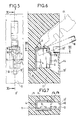
- the connecting piece 1, metallic and good conductor, is conventionally provided with a longitudinal slot 2 formed through one of its walls 3, here called front.
- the connecting piece 1 is obtained by folding a metal blank previously cut from a strip.
- This connection piece 1 comprises a main body of rectangular section which includes the front wall 3, a bottom wall 4 and two cheeks 5 and 6.
- the front wall 3 is composed of two parts, which are separated by the longitudinal slot 2 and which are each formed by a cheek extension 5 or 6 folded perpendicularly towards the inside of the main body.
- These slot edges are designed on the one hand to ensure the cross section of the insulation forming the sheath of a wire without practically start the core of this wire and on the other hand ensure the wedging of this core between the edges of the slot.
- the edges of the slot 2 at the insertion end are symmetrically and obliquely oriented towards each other on either side of the axis XX 'of insertion into the slot 2, so as to form two guide chamfers 7A, 7'A preceding two cutting bevels 7B, 7'B for the insulation of the wires to be connected, which themselves precede two wedging strips 7C, 7'C for the core of these wires.
- FIGS. 2 and 3 comprising retaining teeth 8 for the cores of wires successively inserted into the slot 2, such as the retention teeth 8C on the edge 7C of the connection piece presented in FIG. 2 and the retention teeth 8C1, 8 ' C1 on the edges 7C1, 7'C1 of the part shown in Figure 3.
- the different teeth 8 presented by way of example have triangular teeth inclined in the direction of insertion, the oblique slope of each tooth favoring the compression of the core of the wires during their insertion in force and the part perpendicular to the axis XX 'slowing the movement of souls in the opposite direction to that of insertion.
- connection piece 1 is made as rigid as possible, as shown in FIG. 1, in order to obtain a deformation of the cores rather than a spacing of the slot in order to make possible the successive insertion of several cores in the same slot 2, ensuring sufficient retention for each.
- the length of the cheeks 5 and 6 is preferably limited and the thickness of the blank from which the piece comes from is increased compared to what is provided for the pieces with a self-stripping slot in which the elasticity is played on.
- the part is preferably embedded in a housing with rigid walls opposing the spacing of the slot 2.
- the bottom wall 4 is here extended on the side of the wire insertion end by a short folded tab 9 forming a transverse cavity 10 opening inside the main body behind the slot 2 and towards this slot .
- this is obtained by folding the short part 9 by more than ninety degrees.
- an additional extension shutter 25, here coming from the bottom wall 4 opposite the short folded part 9, makes it possible to connect the connection part to the apparatus which it serves, here not shown, by forming a connecting tab, if necessary.
- connection piece 1 presented in FIG. 1 is intended to be immobilized in a housing of a body made of insulating material 11, molded, which is partially presented in FIGS. 5 to 7.
- connection piece 1 is preferably embedded in the body 11 often formed using two nested pieces as is conventional in particular for the terminal blocks, this being symbolized by the trace YY 'at the level of the insulator in figure 7.
- connection piece 1 which tightly encircles this piece is opened on the one hand by a passage for the additional extension 10 to the apparatus here not shown on the other hand by a wire passage opening 12 (FIG. 7 ) formed along the slot 2.
- the thread passage opening 12 is laterally limited by longitudinal edges 13, 13 ′ formed on the body 11. These edges are oriented parallel to the axis of insertion of the wire into the slot 2, they are separated by a distance less than the outside diameter of the insulation of the wires capable of being connected to the connection piece 1, so as to participate in the holding of these wires by jamming their insulating sheath.
- At least one of the longitudinal edges 13, 13 ′ is provided with a toothing 14 similar to one of those presented in FIG. 2 and 3 for the slot edges 2, this toothing 14 (FIG. 5) is intended to immobilize the sheath of the inserted wires so as to prevent the exit of these wires by a reverse movement from that which they had during their insertion.
- a wire retention device is disposed at the end of the wire passage opening 12 which is close to the wire introduction end of the slot 2, it is intended to prevent the return of the wires, such 19, after insertion by resting on the sheath of the last introduced, if it exceeds a threshold ascent criticism for which it would tend to escape jamming by the edges of the slot 2 and / or the edges of the opening for the passage of the wire 12.
- this retention device is composed of at least two protruding fingers 15, 15 ′ produced at the same level, above the edges 13, 13 ′ of the wire passage opening and near the chamfers of the slot 2 and of the wire passage opening 12.
- These fingers 15, 15 ′ are inclined in the direction of introduction so as to facilitate the entry of the wires into the slot and the opening during their insertion, they are provided to flex under the thrust of the wire, arranged transversely to the slot and the opening during insertion.
- each of them is arranged so that any wire 19 which has passed them, during its introduction, is held by its sheath and by its core, respectively between the edges 13, 13 'and between the edges of slot 2, without being able to escape, as long as the pulling force remains normal, for example of less than fifteen kilogs.
- the width of these fingers 15 and 15 ′ may be such that it closes the passage between the connection piece 1 and the lips 14 and 14 ′, thus avoiding inadvertent introduction of the conductor and not allowing connection to the core of the driver.
- the retention device is composed of two flaps 16, 16 ′ arranged at the same level, each on one of the edges of the wire passage opening 12, of so that the bottom of these flaps is at the level defined above for the free end of the fingers 15, 15 '.
- the flaps 16, 16 'practically contiguous in the longitudinal axis of the wire passage opening 12 are at rest in a quasi-closed position; they are pushed outwards from the body 11, during the insertion of a wire 19 positioned transversely with respect to the slot 2 and at the opening for passage of the wire, under the pressure of the sheath of this wire on their respective upper edges which are arranged obliquely for this purpose relative to the direction of insertion.
- the flaps 16, 16 ′ return elastically to the rest position and then constitute a stop opposing any exit of the wire by a reverse displacement from that of insertion, as above.
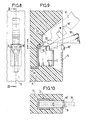
- the wire 19 is connected using a tool blade 17 partially shown in FIGS. 6, 9, 11 and 12.
- This tool blade 17 is intended to push the wire 19, into the slot 2 and the wire passage opening 12, until it is definitively positioned during its insertion, it is here designed with two notches 18 and 18 ' allowing it to put pressure on the wire 19 introduced, without itself penetrating into the slot 2 and into the wire passage opening 12.
- this tool blade 17 is provided with a handle that is not shown allowing it to be maneuvered, the other end is provided with a bearing end piece 20 intended to be housed in the transverse cavity 10 to bear thereon when the tool is used as a lever, during insertion.
- This support end piece 20 has a so-called hooking surface making a sharp angle at its upper end, so as to lock in the cavity 10 of the connection piece where it is desired to insert a wire, when pressure is applied on the handle, towards the slot, for the connection of the wire.
- the blade part 17 carrying the bearing end piece and the notches is arched relative to the rest of the blade to facilitate the support of this blade on the wire in the connection zone.
- the body 11 has for this purpose a tool passage opening 22 above the wire passage opening 12 and consequently on the other side of the retention device with respect to the teeth 14.
- This tool passage opening 22 is arranged so that the insulating body 11 covers the folded tab 9 of the connection piece 1, above the transverse cavity 10, to enable it to resist the efforts of wire insertion. ; it allows the introduction of the bearing endpiece in the transverse cavity 10 in the presence of a wire 19 in the standby insertion position, as shown in the figures indicated above, as well as the movements of the blade of tool along the axis of slot 2, until a wire is completely inserted at the bottom of the slot.
- Figures 11A, 11B, 11C show three phases of connection of a wire.
- the connection piece 1 Prior to connection, the connection piece 1 is the only one embedded in the body 11 and a non-stripped wire is introduced therein abutting against the bottom wall of the piece and the tool blade 17 in the preparatory position, here high, with its bearing end piece 20 in the transverse cavity 10 of the part.
- the tool blade is then used as a lever.
- the application of a force, here from top to bottom, on the handle of the tool tends to pivot the blade around the fixed fulcrum, which then constitutes the transverse cavity 10-end piece 20, the core of said wire 19 sinks while deforming in slot 2 as well as the sheath of this wire in the opening for passage of wire 12, the sheath being sectioned by the bevels placed at the inlet of slot 2.
- the tool can be removed either permanently or for the introduction of another wire as shown in Figures 12A to 12C.
- a new wire 19 ′ is then positioned for insertion in the manner described above, with its non-stripped end in abutment against the bottom wall 4 of the connection piece and above the slot 2 and the passage opening of wire 12 almost orthogonally to them.
- the support end piece 20 of the tool blade is positioned in the cavity and by pressure the tool blade is pressed in its intermediate zone against the sheath of the wire 19 'which it drives in the slot and the opening wire passage, until it comes into contact with the wire 19 previously inserted.
- the tool is then either removed or possibly reused for a new insertion in the connection piece 1.
- connection piece according to the invention may also have more than one slot, such as the connection piece 1 ′ shown in FIG. 13, which has two longitudinal slots for wedging the web 2'A, 2'B possibly allowing the height of the room to be reduced at the cost of its enlargement when more than one conductive wire 13 has to be connected.
- the transverse cavity 10 for support the end of a tool blade is then common for the two slots 2'A, 2'B which then preferably have two separate openings for the passage of wire in the insulating body here not shown.
- the dimensioning of the slots 2 ′ A, 2 ′ B is possibly different, for example in width as shown in FIG. 13, which then allows the connection of wires of very different diameters.
- connection piece includes an additional sheath wedging slot 23 in addition to the web jamming slot, for example in order to obtain high rigidity.
- connection piece 1 "obtained is housed in the insulating body in a manner completely similar to that provided for the connection piece 1, as presented in FIGS. 8, 9, 10 and therefore has an opening for wire passage, preferably without retaining teeth, and a tool passage opening.
- the connecting piece 1 "itself is obtained by folding a metal blank, it comprises a body of rectangular section provided with a core wedge slot 2" on one of its walls 3 "so completely identical to that previously provided for connection piece 1.
- the wall 3 is bordered by two cheeks 5" and 6 "whose ends are folded perpendicularly towards each other to form a front wall 23", the non-contiguous edges of these folded ends forming a longitudinal slot 24 "in the front wall 23 ".
- the slots 2 "and 24" are delimited by smooth or toothed edges as indicated above, the teeth aiming to retain either the cores or the sheaths of the connected conducting wires.
- the slot 24 " is provided, in width and shape, to ensure the jamming of the insulating sheaths of the wires and is therefore located between the core jamming slot 2" and the opening for the passage of wire in the body of insulating material where the 1 "connection piece is mounted.
- the body of rectangular section comprising the slots 2 "and 24" extends on the other side of the wall 3 "relative to the wall 23".
- the 20 "extension obtained is for example opposite the end wire insertion into the slot 2 "and continues itself by a perpendicular fold, forming a bottom wall 4" and carrying at its end the tab 9 "which determines the transverse cavity 10" allowing the support of a tool blade tip as defined above, for inserting the wires into the slots.
- connection piece 1 In a known manner, it is possible for example to cut in one or the other wall of the connection piece 1 "as well as in the other pieces, connection tabs making it possible to connect the connection piece as necessary an apparatus, or to weld, or to rivet the necessary connecting elements.
Applications Claiming Priority (2)
| Application Number | Priority Date | Filing Date | Title |
|---|---|---|---|
| FR8510083 | 1985-07-02 | ||
| FR8510083A FR2584538B1 (fr) | 1985-07-02 | 1985-07-02 | Agencement de connexion auto-denudant encastre pour appareillage electrique et outil de connexion pour un tel agencement |
Publications (2)
| Publication Number | Publication Date |
|---|---|
| EP0208233A1 true EP0208233A1 (de) | 1987-01-14 |
| EP0208233B1 EP0208233B1 (de) | 1990-05-16 |
Family
ID=9320879
Family Applications (1)
| Application Number | Title | Priority Date | Filing Date |
|---|---|---|---|
| EP86108932A Expired - Lifetime EP0208233B1 (de) | 1985-07-02 | 1986-07-01 | Eingebaute Vorrichtung für elektrische Apparate zur abisolierfreien Verbindung und Verbindungswerkzeug für eine solche Vorrichtung |
Country Status (7)
| Country | Link |
|---|---|
| US (1) | US4722699A (de) |
| EP (1) | EP0208233B1 (de) |
| JP (1) | JPH0626150B2 (de) |
| BR (1) | BR8603066A (de) |
| DE (1) | DE3671331D1 (de) |
| ES (1) | ES2000445A6 (de) |
| FR (1) | FR2584538B1 (de) |
Cited By (3)
| Publication number | Priority date | Publication date | Assignee | Title |
|---|---|---|---|---|
| EP0270480A2 (de) * | 1986-12-03 | 1988-06-08 | KRONE Aktiengesellschaft | Vorrichtung zum Anschliessen von Kabeladern an Schneidklemmkontakten von Dropwire-Anschlussleisten der Fernmeldetechnik |
| EP0570994A2 (de) * | 1986-12-03 | 1993-11-24 | KRONE Aktiengesellschaft | Vorrichtung zum Anschliessen von Kabeladern an Schneidklemmkontakten von Dropwire-Anschlussleisten der Fernmeldetechnik |
| EP0714155A3 (de) * | 1994-11-22 | 1996-08-14 | Panduit Corp | Drahtanschlusswerkzeug für Modularsteckverbinder eines Telefons |
Families Citing this family (14)
| Publication number | Priority date | Publication date | Assignee | Title |
|---|---|---|---|---|
| JPH0524131Y2 (de) * | 1986-11-07 | 1993-06-18 | ||
| DE3912273A1 (de) * | 1989-04-14 | 1990-10-18 | Minnesota Mining & Mfg | Verbinder fuer isolierte leiter |
| US5139433A (en) * | 1991-04-16 | 1992-08-18 | Bruce Bohaty | Special connector members for small electrical light emitting devices, bases, and sockets |
| US5417582A (en) * | 1993-10-18 | 1995-05-23 | Tang; Wen-Yun | Connector terminals for use in computers |
| DE4437022C1 (de) * | 1994-10-08 | 1996-02-22 | Krone Ag | Anschlußelement |
| US5756972A (en) * | 1994-10-25 | 1998-05-26 | Raychem Corporation | Hinged connector for heating cables of various sizes |
| JP2952587B1 (ja) | 1998-03-30 | 1999-09-27 | 株式会社貝印刃物開発センター | 安全かみそり |
| US6152760A (en) * | 1999-03-23 | 2000-11-28 | The Whitaker Corporation | Pivoting wire carrier for aerial drop wire and terminal therefor |
| DE10039962C2 (de) * | 2000-08-16 | 2003-10-23 | Siemens Ag | Elektrisches Gerät mit mindestens einer Schneidklemmeinrichtung |
| US6419518B1 (en) | 2001-02-16 | 2002-07-16 | Y-Connect, Incorporated | Insulation displacement contact for use with fine wires |
| US6431903B1 (en) | 2001-03-07 | 2002-08-13 | Y-Connect Incorporated | Insulation displacement contact for use with fine wires |
| KR101026503B1 (ko) * | 2009-09-17 | 2011-04-05 | 이영환 | 전선 이음 커넥터 |
| US8512066B2 (en) | 2009-09-17 | 2013-08-20 | Jowoo-Tech Co. Ltd | Electric wire connector for press connecting electric wires |
| LU102037B1 (de) * | 2020-09-09 | 2022-03-09 | Phoenix Contact Gmbh & Co | Klemme und Werkzeug zum Anschluss eines elektrischen Leiters an die Klemme sowie Verfahren zum Anschließen eines elektrischen Leiters an die Klemme |
Citations (3)
| Publication number | Priority date | Publication date | Assignee | Title |
|---|---|---|---|---|
| US4037906A (en) * | 1976-03-22 | 1977-07-26 | Gte Sylvania Incorporated | Electrical connector and contact |
| FR2419594A1 (fr) * | 1978-03-07 | 1979-10-05 | Nozick Jacques | Element de contact electrique a connexion auto-denudante pour fil ou cable |
| GB2083297A (en) * | 1980-09-08 | 1982-03-17 | Siemon Co | A block for housing electrically conductive wire connector elements |
Family Cites Families (9)
| Publication number | Priority date | Publication date | Assignee | Title |
|---|---|---|---|---|
| GB197808A (en) * | 1922-04-05 | 1923-05-24 | Newman Robert Bennet | Improvements connected with frames of school desks and the like |
| US3812449A (en) * | 1973-04-30 | 1974-05-21 | Minnesota Mining & Mfg | Terminal strip |
| US3845455A (en) * | 1973-10-12 | 1974-10-29 | Amp Inc | Tubular conductor-in-slot connecting device |
| JPS5532390Y2 (de) * | 1976-05-19 | 1980-08-01 | ||
| FR2503464A1 (fr) * | 1981-04-03 | 1982-10-08 | Alsthom Cgee | Bloc de jonction a raccordement electrique sans denudage |
| FR2516711A1 (fr) * | 1981-11-17 | 1983-05-20 | Alsthom Cgee | Borne de raccordement de fil electrique sans denudage |
| US4452501A (en) * | 1982-04-30 | 1984-06-05 | General Motors Corporation | Electrical connector with latch terminal |
| JPS5959474U (ja) * | 1982-06-25 | 1984-04-18 | 日本モレツクス株式会社 | 圧接型電気コネクタ |
| US4508411A (en) * | 1983-03-29 | 1985-04-02 | Amp Incorporated | Wire stuffing cover |
-
1985
- 1985-07-02 FR FR8510083A patent/FR2584538B1/fr not_active Expired
-
1986
- 1986-06-27 US US06/879,773 patent/US4722699A/en not_active Expired - Fee Related
- 1986-07-01 ES ES8600069A patent/ES2000445A6/es not_active Expired
- 1986-07-01 BR BR8603066A patent/BR8603066A/pt not_active IP Right Cessation
- 1986-07-01 EP EP86108932A patent/EP0208233B1/de not_active Expired - Lifetime
- 1986-07-01 JP JP61154956A patent/JPH0626150B2/ja not_active Expired - Lifetime
- 1986-07-01 DE DE8686108932T patent/DE3671331D1/de not_active Expired - Fee Related
Patent Citations (3)
| Publication number | Priority date | Publication date | Assignee | Title |
|---|---|---|---|---|
| US4037906A (en) * | 1976-03-22 | 1977-07-26 | Gte Sylvania Incorporated | Electrical connector and contact |
| FR2419594A1 (fr) * | 1978-03-07 | 1979-10-05 | Nozick Jacques | Element de contact electrique a connexion auto-denudante pour fil ou cable |
| GB2083297A (en) * | 1980-09-08 | 1982-03-17 | Siemon Co | A block for housing electrically conductive wire connector elements |
Cited By (5)
| Publication number | Priority date | Publication date | Assignee | Title |
|---|---|---|---|---|
| EP0270480A2 (de) * | 1986-12-03 | 1988-06-08 | KRONE Aktiengesellschaft | Vorrichtung zum Anschliessen von Kabeladern an Schneidklemmkontakten von Dropwire-Anschlussleisten der Fernmeldetechnik |
| EP0270480A3 (en) * | 1986-12-03 | 1989-09-06 | Krone Aktiengesellschaft | Apparatus for the connection of cable cores to cutting and clamping contacts of "drop wire" connecting blocks for the telecommunications |
| EP0570994A2 (de) * | 1986-12-03 | 1993-11-24 | KRONE Aktiengesellschaft | Vorrichtung zum Anschliessen von Kabeladern an Schneidklemmkontakten von Dropwire-Anschlussleisten der Fernmeldetechnik |
| EP0570994A3 (en) * | 1986-12-03 | 1995-09-13 | Krone Ag | Apparatus for the connection of cable cores to cutting and clamping contacts of drop wire connection blocks for the telecommunications |
| EP0714155A3 (de) * | 1994-11-22 | 1996-08-14 | Panduit Corp | Drahtanschlusswerkzeug für Modularsteckverbinder eines Telefons |
Also Published As
| Publication number | Publication date |
|---|---|
| DE3671331D1 (de) | 1990-06-21 |
| FR2584538B1 (fr) | 1987-09-25 |
| JPH0626150B2 (ja) | 1994-04-06 |
| BR8603066A (pt) | 1987-02-17 |
| US4722699A (en) | 1988-02-02 |
| JPS6210883A (ja) | 1987-01-19 |
| EP0208233B1 (de) | 1990-05-16 |
| FR2584538A1 (fr) | 1987-01-09 |
| ES2000445A6 (es) | 1988-03-01 |
Similar Documents
| Publication | Publication Date | Title |
|---|---|---|
| EP0208233B1 (de) | Eingebaute Vorrichtung für elektrische Apparate zur abisolierfreien Verbindung und Verbindungswerkzeug für eine solche Vorrichtung | |
| EP0037758B1 (de) | Elektrische Vorrichtung zum automatischen Verbinden, insbesondere Verbinder für elektrische Leiter | |
| EP0749129B1 (de) | Flachkabel und Entmantelungszange | |
| CA2987825A1 (fr) | Clip metallique de connexion electrique d'un fil conducteur a un element metallique | |
| EP0247360B1 (de) | Verbindungsanordnung mit einem Schlitz für einen elektrischen Leiter und Spitze für ein entsprechendes Verbindungswerkzeug | |
| EP0243887A1 (de) | Verbindungsanordnung mit abisolierendem Schlitz für einen elektrischen Leiter | |
| FR2777702A1 (fr) | Dispositif de connexion auto-denudant | |
| EP1166394A1 (de) | Schneidklemmverbindungsanordnung für zwei elektrische kabel | |
| FR2761534A1 (fr) | Agencement de connexion electrique et module, notamment de raccordement, comportant un tel agencement | |
| FR2504315A1 (fr) | Element de connexion et dispositif de connexion, comportant de tels elements | |
| EP0106768A1 (de) | Verbindungsvorrichtung für einen elektrischen Leiter | |
| FR2782194A1 (fr) | Dispositif de connexion auto-denudant | |
| EP1045491B1 (de) | Verbindungsverfahren und -anordnung für Anschlussklemmen | |
| FR2566967A1 (fr) | Borne pour connexion de conducteur electrique par ressort de pressage | |
| FR2782196A1 (fr) | Dispositif de connexion a fente denudante pour fil electrique | |
| EP0881709B1 (de) | Geschlitzte Anschlussklemme für eine Verbindungsanordnung für mindestens eine elektrische Leiter | |
| EP1928058B9 (de) | Automatische elektrische Verbindungsklemme | |
| FR2803442A1 (fr) | Piece de connexion auto-denudante pouvant etre reliee a une piece de connexion voisine | |
| EP3349305A1 (de) | Verbessertes elektrisches anschlusskit | |
| EP0708493B1 (de) | Anschlussklemme mit selbstabisolierender, mittels einer Schraube betätigbarer Verbindungsvorrichtung | |
| EP0662737B1 (de) | Geschlitzte Anschlussvorrichtung für elektrisches Kabel verbunden mit einem Kontaktelement in einer Dose | |
| EP0298819B1 (de) | Elektrischer Steckverbinder | |
| FR2835974A1 (fr) | Dispositif de connexion a deplacement d'isolant | |
| EP1496575B1 (de) | Steckkontakt | |
| EP0470882A1 (de) | Elektrischer Schneidklemmenkontakt |
Legal Events
| Date | Code | Title | Description |
|---|---|---|---|
| PUAI | Public reference made under article 153(3) epc to a published international application that has entered the european phase |
Free format text: ORIGINAL CODE: 0009012 |
|
| AK | Designated contracting states |
Kind code of ref document: A1 Designated state(s): DE FR GB IT |
|
| 17P | Request for examination filed |
Effective date: 19870713 |
|
| 17Q | First examination report despatched |
Effective date: 19890125 |
|
| GRAA | (expected) grant |
Free format text: ORIGINAL CODE: 0009210 |
|
| RAP1 | Party data changed (applicant data changed or rights of an application transferred) |
Owner name: SOCIETE ANONYME DITE: CEGELEC |
|
| AK | Designated contracting states |
Kind code of ref document: B1 Designated state(s): DE FR GB IT |
|
| REF | Corresponds to: |
Ref document number: 3671331 Country of ref document: DE Date of ref document: 19900621 |
|
| GBT | Gb: translation of ep patent filed (gb section 77(6)(a)/1977) | ||
| ITF | It: translation for a ep patent filed |
Owner name: JACOBACCI & PERANI S.P.A. |
|
| PLBE | No opposition filed within time limit |
Free format text: ORIGINAL CODE: 0009261 |
|
| STAA | Information on the status of an ep patent application or granted ep patent |
Free format text: STATUS: NO OPPOSITION FILED WITHIN TIME LIMIT |
|
| 26N | No opposition filed | ||
| ITTA | It: last paid annual fee | ||
| REG | Reference to a national code |
Ref country code: FR Ref legal event code: TP |
|
| REG | Reference to a national code |
Ref country code: GB Ref legal event code: IF02 |
|
| PGFP | Annual fee paid to national office [announced via postgrant information from national office to epo] |
Ref country code: FR Payment date: 20040625 Year of fee payment: 19 |
|
| PGFP | Annual fee paid to national office [announced via postgrant information from national office to epo] |
Ref country code: GB Payment date: 20040720 Year of fee payment: 19 |
|
| PGFP | Annual fee paid to national office [announced via postgrant information from national office to epo] |
Ref country code: DE Payment date: 20040921 Year of fee payment: 19 |
|
| PG25 | Lapsed in a contracting state [announced via postgrant information from national office to epo] |
Ref country code: IT Free format text: LAPSE BECAUSE OF NON-PAYMENT OF DUE FEES;WARNING: LAPSES OF ITALIAN PATENTS WITH EFFECTIVE DATE BEFORE 2007 MAY HAVE OCCURRED AT ANY TIME BEFORE 2007. THE CORRECT EFFECTIVE DATE MAY BE DIFFERENT FROM THE ONE RECORDED. Effective date: 20050701 Ref country code: GB Free format text: LAPSE BECAUSE OF NON-PAYMENT OF DUE FEES Effective date: 20050701 |
|
| PG25 | Lapsed in a contracting state [announced via postgrant information from national office to epo] |
Ref country code: DE Free format text: LAPSE BECAUSE OF NON-PAYMENT OF DUE FEES Effective date: 20060201 |
|
| GBPC | Gb: european patent ceased through non-payment of renewal fee |
Effective date: 20050701 |
|
| PG25 | Lapsed in a contracting state [announced via postgrant information from national office to epo] |
Ref country code: FR Free format text: LAPSE BECAUSE OF NON-PAYMENT OF DUE FEES Effective date: 20060331 |
|
| REG | Reference to a national code |
Ref country code: FR Ref legal event code: ST Effective date: 20060331 |